Chapter 4 Imaging Soft Tissues of the Neck
Imaging of soft tissues of the neck can be essential in the evaluation of patients with a variety of chief complaints, including neck trauma, ingested or aspirated foreign body, nontraumatic neck pain and swelling, dysphagia and voice change, visible or palpable mass, and central nervous system complaints with possible vascular causes. The neck contains vascular, nerve, airway, gastrointestinal, and bony structures, any of which may be the source of pain. Remember that referred pain from other regions of the body may present with neck pain, so a broad differential diagnosis should be entertained in formulating an imaging plan. Fascial planes connect compartments of the neck with the mediastinum and thoracic prevertebral spaces, posing a risk of spread of infection from the neck to these regions. Imaging of the neck often is performed with imaging of the head or chest, as structures passing through the neck extend into these adjacent body regions. In this chapter, we explore the modalities available for soft-tissue cervical imaging, discuss clinical indications for imaging in a variety of chief complaints, and review some characteristic findings of important pathology, using the figures throughout the chapter. Imaging of the soft tissues of the cervical spinal cord and ligaments are discussed in Chapter 3.
Who Needs Soft-Tissue Imaging? Which Imaging Modality Should Be Used?
Given the range of potential pathology discussed earlier, it should come as little surprise that no single clinical decision rule can be used to inform decisions for soft-tissue neck imaging. Instead, the differential diagnosis under consideration should drive the imaging decision, based on expected features of the pathology and the capabilities of each modality. Dilemmas for the practitioner include whether imaging is required and, if so, whether to screen with a limited test such as x-ray, rather than incurring the additional cost and radiation exposure of computed tomography (CT). Some soft-tissue neck abnormalities are best assessed with neither x-ray nor CT but rather with ultrasound, magnetic resonance imaging (MRI), fluoroscopy, or techniques such as bronchoscopy and esophagoscopy. First we consider some general principles regarding the available imaging modalities: x-ray, CT, ultrasound, and MRI. Fluoroscopy is discussed later with regard to esophageal pathology.
Soft-Tissue X-ray of the Neck
Plain x-ray (Figures 4-1 and 4-2) provides limited information about the soft tissues of the neck. X-ray relies on differentiation of adjacent structures using four basic tissue densities: air, fat, water (which includes soft tissues, both solid organs such as muscle and fluids such as blood), and bone (sometimes called metal density). As we discuss in detail in Chapter 5 with regard to chest x-ray, two adjacent structures with the same basic tissue density are indistinguishable on x-ray; no border is seen separating them. When two tissues of different density abut one another, the transition is clear. For this reason, x-rays can demonstrate abnormal soft-tissue air (Figures 4-3 to 4-5), deviation or compression of normal air-filled structures (the trachea particularly) (Figures 4-3 and 4-6 to 4-10), air–fluid levels suggesting abscess, and radiopaque foreign bodies (Figures 4-11 to 4-15), as all of these involve a contrast between two key tissue densities. Unfortunately, many of the soft-tissue abnormalities of interest to us as emergency physicians may not involve such a contrast. Instead, one soft-tissue structure may abut a second soft-tissue structure, and these are indistinguishable on x-ray. This leaves an array of potentially devastating forms of neck pathology that are poorly assessed with x-ray. Examples include vascular dissections, abscesses, and subtle soft-tissue masses that may not be seen on x-ray.
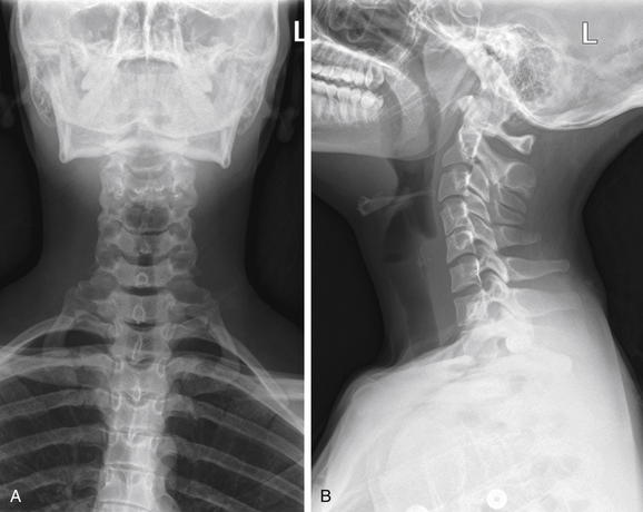
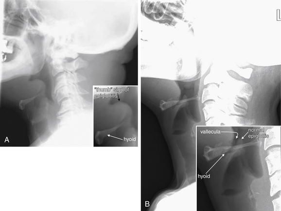
Figure 4-1 Normal soft-tissue neck x-ray.
A soft-tissue neck series consists of an anterior–posterior (AP) (A) and a lateral (B) x-ray of the neck. Compared with a cervical spine x-ray, the images are intentionally underexposed to allow soft tissues to be examined. Figure 4-2 examines close-ups from these images.
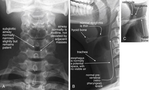
Figure 4-2 Normal soft-tissue neck x-ray.
A, Anterior–posterior view. B, Lateral view. C, Close-up focusing on epiglottis. Compare with later figures showing pathology. This young adult has a normal x-ray. Note the normal epiglottis and vallecula, the position of the hyoid, and the thickness of the normal retropharyngeal (prevertebral) spaces. These become abnormal in disease states such as croup, epiglottitis, and retropharyngeal abscess.
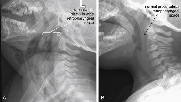
Figure 4-3 Retropharyngeal abscess with retropharyngeal air.
This 22-month-old boy presented with drooling and hyperextension of the neck. He had been seen days earlier and diagnosed with a likely viral pharyngitis. A, Lateral soft-tissue x-ray of the neck shows extensive air (black) dissecting into tissue planes of the deep spaces of the neck, as well as the submental area. The retropharyngeal space is dramatically wide with visible air and is deviating the airway forward. Classically, soft-tissue x-ray in the setting of retropharyngeal abscess may also reveal an air–fluid level in the retropharyngeal space—a finding not present in this image. B, Normal soft-tissue x-ray is shown for comparison. The next figure demonstrates the computed tomography images from this patient. The patient was intubated and ultimately taken to the operating room for surgical drainage, which confirmed abscess.
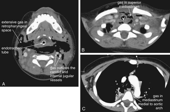
Figure 4-4 Retropharyngeal abscess: CT with intravenous (IV) contrast, soft-tissue windows.
Same patient as Figure 4-3. Dramatic dissection of gas (black) is seen in the retropharyngeal space. A, The endotracheal tube is visible. Air outlines the carotid and internal jugular vessels. B, Air is seen dissecting into the superior mediastinum. C, Gas is seen medial to the aortic arch. This case highlights the dangers of retropharyngeal processes, as infections in this location can readily extend to the mediastinum. Interestingly, the patient’s infection was caused by yeast, and the extensive gas collection may have been carbon dioxide produced by the Candida species.
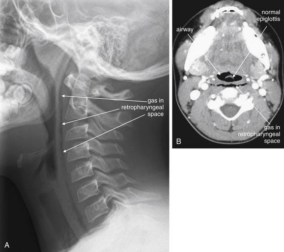
Figure 4-5 Retropharyngeal air.
This 10-year-old boy complained of chest pain and dysphagia after coughing. A, Lateral soft-tissue neck x-ray reveals a thin stripe of air in the retropharyngeal space, extending from the skull base to the chest. Given the clinical history, the airway or lungs were the likely source of the air leak. Compare with the normal soft-tissue x-ray in a Figure 4-1, B. The patient underwent computed tomography (CT) of the neck and chest with intravenous contrast but the source of the air was not explicitly identified. B, Neck CT (shown on soft-tissue windows) shows a thin stripe of retropharyngeal air, correlating with the soft-tissue x-ray. Noncontrast CT could have revealed this finding, although contrast was given because of the possibility of an infectious source that might enhance with contrast.
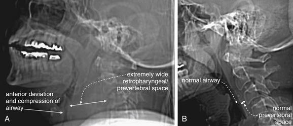
Figure 4-6 Retropharyngeal hematoma with airway compromise.
This 67-year-old woman presented with neck pain after tripping, falling forward, and striking her nose against a windowsill. Although she did not lose consciousness, she reported a popping sound from her neck as hyperextension occurred. During computed tomography (CT) scan of the head and cervical spine, the patient developed stridor and was immediately removed from the CT scanner. Within 1 minute, she experienced a respiratory arrest and was intubated with difficulty. CT scans before and after her intubation are shown in the next figure. In this figure, lateral computed tomography (CT) scout images are shown, as these approximate the findings from a lateral x-ray, had one been performed. A, Scout CT image performed before the patient complained of dyspnea shows an extremely wide retropharyngeal space and airway compression. B, Normal scout film is shown for comparison.
Beware of placing a patient supine for CT, because this can worsen airway compromise.
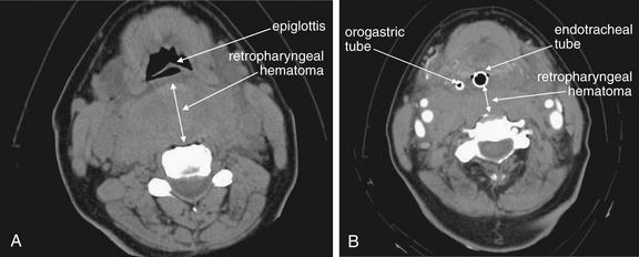
Figure 4-7 Retropharyngeal hematoma with airway compromise.
Same patient as Figure 4-6. CT scans before and after her intubation are shown.
A, The caudadmost slice of her noncontrast facial CT shows a dramatic retropharyngeal hematoma displacing the airway forward (double arrow). The normal retropharyngeal space is less than 6 to 8 mm at C1-3 and 18 mm at C6 or C7, while this patient’s hematoma was more than 40 mm in thickness. B, After intubation, the patient underwent repeat CT with intravenous contrast to assess for active hemorrhage—none was found. The retropharyngeal hematoma is still visible, 20 mm in thickness at this level posterior to the endotracheal tube (double arrow). But for the presence of the endotracheal tube, the hematoma completely obscures the airway. The hematoma extended caudad into the mediastinum. The patient had no spinal injury detected, and coagulation studies on the patient were normal.
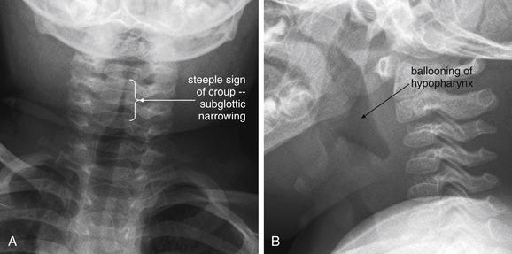
This 19-month-old, fully immunized boy presented with acute onset of stridor without fever. The patient’s mother was uncertain whether he might have ingested a foreign body, and x-rays of the soft tissues of the neck and chest were obtained. A, The anterior–posterior neck x-ray shows a classic example of the long-segment subglottic narrowing typical of croup, called the “steeple sign” for its resemblance to a traditional peaked church steeple. B, The prevertebral soft tissues are normal, and the epiglottis appears normal on lateral x-ray. The hypopharynx appears ballooned, which is common in croup. X-rays are not needed routinely to confirm croup when a typical history and physical is present. The primary purpose of x-rays in this setting is to rule out other etiologies, such as foreign body aspiration or epiglottitis.
A, Lateral cervical soft-tissue x-ray showing epiglottitis in a 64-year-old man. The epiglottis is thickened, showing a classic “thumb sign.” B, Normal soft-tissue x-ray for comparison. The brightness and contrast have been increased to point out the normal thin epiglottis, which is partially hidden behind the hyoid bone. The vallecula is seen as a narrow space anterior to the epiglottis. An anterior–posterior (AP) x-ray is not shown for this case, because the AP view is not usually diagnostic in cases of epiglottitis.
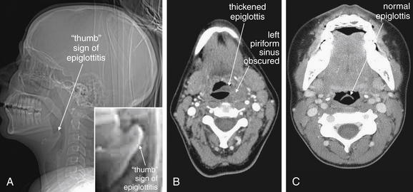
Figure 4-10 Epiglottitis, seen on CT with IV contrast, soft tissue windows.
While a patient with suspected impending airway occlusion should not be placed supine in a CT scanner, CT can be a valuable tool for diagnosis of airway and retropharyngeal pathology. In this patient with epiglottitis, the CT scout image (A) demonstrates a thumb sign similar to the plain film findings in Figure 4-9. The axial image (B) also demonstrates an enlarged epiglottis, with an obscured left piriform sinus. A normal epiglottis in another patient is shown for comparison (C). The normal epiglottis is a thin crescent.
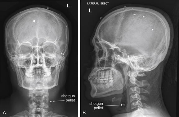
Figure 4-11 Penetrating neck trauma.
This 30-year-old man was wounded with a shotgun. The patient ducked his head at the moment of the blast, and most of the shot impacted superficially in his scalp. However, one pellet entered the mental vertex of his mandible and lodged in the anterolateral neck. A, Anterior–posterior view shows the pellet to be in the lateral left neck, in the region of the carotid artery. B, The lateral x-ray combined with the AP view shows the pellet is not superficial. Computed tomography was performed to assess the carotid artery and adjacent structures Figure 4-12.
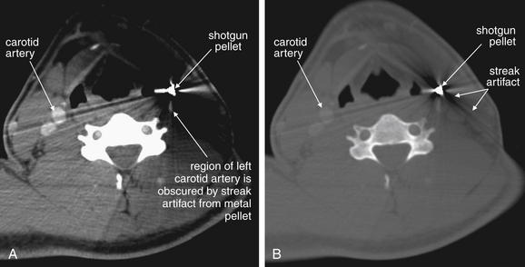
Figure 4-12 Penetrating neck trauma.
Same patient as Figure 4-11. Computed tomography with intravenous contrast was performed to assess the carotid artery and adjacent structures. A, Soft-tissue windows. B, Bone windows. The pellet creates extensive metallic streak artifact, which completely obscures the vessels of interest. Conventional angiography could be performed in circumstances such as these, because it is free of this type of artifact.
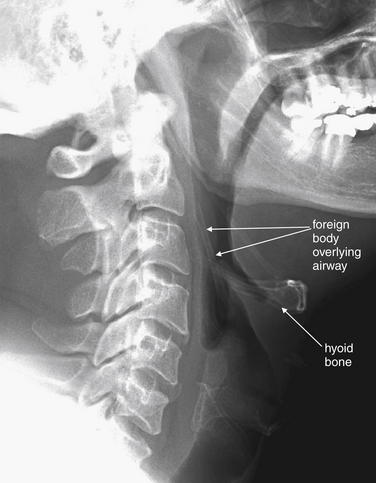
Figure 4-13 Airway foreign body: Chicken bone.
This 47-year-old man was unable to speak after eating chicken. The patient pointed to his larynx, indicating a foreign body sensation. Lateral neck x-ray shows a foreign body superior to the larynx, perpendicular to the hyoid bone. Remember that you must look at both the anterior–posterior (AP) and the lateral view to localize an object; in this case, however, the object was not visible on the AP view, because it overlay the spine.
Smaller foreign bodies such as fish bones may not be visible on plain film but may be identified on computed tomography. In this case, the patient was taken to the operating room for removal of the object, which was found to be a 4-cm chicken bone in the right piriform sinus.
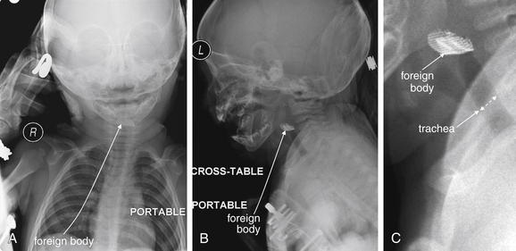
Figure 4-14 Airway foreign body: Metal mesh.
The role of plain films in evaluation of soft tissues of the neck is limited, but when the patient’s airway is threatened, plain film may offer the only safe imaging modality. Portable plain films with the patient in a “position of comfort” may offer some diagnostic information. CT in a supine position may further compromise airway patency.
In this toddler, parents reported sudden stridor but did not witness an ingestion or aspiration. Portable x-ray revealed a radiopaque mesh object in the airway. The patient was taken emergently to the operating room for removal. Plastic or organic material may not be visible on plain x-ray. A, Anterior–posterior view. B, Lateral view. C, Close-up from B.
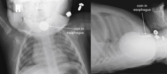
Figure 4-15 Esophageal foreign bodies.
This 11-month-old presented with drooling after being witnessed to place a penny in his mouth. X-ray confirms a circular object apparently lodged in the esophagus. A, Anterior–posterior (AP). B, Lateral. Coins lodged in the esophagus tend to assume an “en face” position, with a circular appearance on the AP view (think British oesophagus for the O appearance of an esophageal coin). Coins lodged in the trachea tend to assume an “edge-on” linear appearance on the AP view, apparently directed to that position by the incomplete tracheal rings. This patient was taken to the operating suite for removal of the coin, which was found to be lodged in the esophagus at the level of the cricopharyngeus.
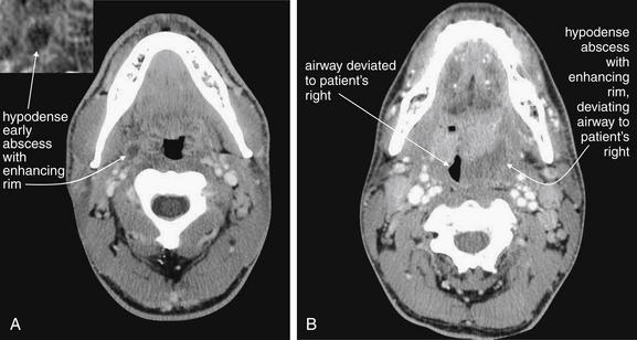
Figure 4-16 Peritonsillar abscess.
A classic peritonsillar abscess requires no imaging, as it has a characteristic appearance on physical examination, with a deviated uvula and peritonsillar mass. In reality, some patients present with early abscesses that are not visible, and others experience too much trismus to allow a complete exam. If more information is needed and the airway appears sufficiently patent for the patient to lie supine safely, intravenous (IV) contrast-enhanced computed tomography can provide excellent diagnostic information. IV contrast leads to “ring enhancement,” an increase in the density on the periphery of an abscess caused by increased blood flow.
A, A small peritonsillar abscess is beginning to form, visible as a hypodense area with slight surrounding enhancement. B, A larger hypodense abscess has formed and is deviating the airway.
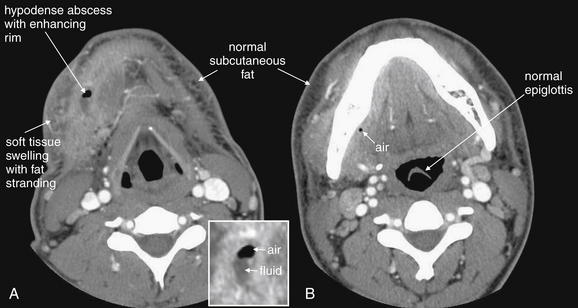
Figure 4-17 Anterior neck abscess, possibly arising from a dental infection.
In this soft-tissue neck computed tomography with intravenous contrast viewed on soft tissue windows, a hypodense abscess containing fluid (dark gray) and air (black) is present in the patient’s right neck in a submandibular position. A, Soft-tissue changes including swelling and inflammatory stranding (smoky appearance) of subcutaneous fat are present (compare with opposite side). B, A tiny fleck of air is visible just medial to the mandible, suggesting that infection may have arisen from a mandibular tooth.
What Information Can Be Gleaned from a Portable Soft-Tissue Neck X-ray? How Should It Be Interpreted?
Portable anterior–posterior (AP) and lateral soft-tissue neck x-rays provide basic information about the airway, as described earlier. Like a focused assessment with sonography for trauma (FAST), the soft-tissue neck film should be assessed by the emergency physician with several specific clinically relevant questions in mind. As you interpret an x-ray, ask yourself each of these questions, rather than simply looking at the x-ray, and assess the x-ray for relevant findings.
TABLE 4-1 Normal Prevertebral Soft-Tissue Thickness
| Imaging Modality and Location | Thickness |
|---|---|
| X-ray | |
| Retrocricoid soft-tissue thickness (x-ray) | 0.7× diameter of C5 vertebral body |
| Retrotracheal soft-tissue thickness (x-ray) | 1.0× diameter of C5 vertebral body |
| CT | |
| C1 | 8.5 mm |
| C2 | 6 mm |
| C3 | 7 mm |
| C4-5 | Not determined because of variable position of esophagus and larynx |
| C6 | 18 mm |
| C7 | 18 mm |
From Chen MY, Bohrer SP. Radiographic measurement of prevertebral soft tissue thickness on lateral radiographs of the neck. Skeletal Radiol 1999;28(8):444-6; Rojas CA, Vermess D, Bertozzi JC, et al. Normal thickness and appearance of the prevertebral soft tissues on multidetector CT. AJNR Am J Neuroradiol 30(1):136-41, 2009.
Soft-Tissue Neck CT
CT is clearly superior to x-ray, as it is able to distinguish a subtler spectrum of tissue densities. CT scan readily distinguishes air, fat, fluid, solid soft tissues of muscle density, and bone. The window setting on CT (discussed in detail later) can be adjusted to highlight a particular tissue density, but on all window settings these tissues are color coded from black (lowest density) to white (highest density). On soft-tissue windows, which are key in our evaluation of neck soft-tissue pathology, air is black, fat is a dark gray (nearly black), fluids such as blood or pus are an intermediate gray, solid tissues are a slightly lighter gray, and high-density material such as bone or metal are white. Lung window settings are sometimes used to evaluate the neck, as air becomes quite evident (black) against all other tissue densities, which appear white on this window setting. Bone windows also highlight air (black) in contrast to all other tissues. Nonstandard window settings can be selected to highlight pathology. The precise density of a tissue can also be measured on CT scan on most picture archiving and communication systems (PACSs) (the name given to a digital diagnostic imaging interface). The computer cursor can be placed over a single pixel or a broader region of interest, and the density of the tissue in Hounsfield units (HU) is reported. On the Hounsfield scale (Figure 000), water has a density of 0 HU, air has a density of −1000 HU, and the highest-density bone has a density of +1000 HU. Nonbiological high-density substances such as metal foreign bodies have densities exceeding +1000 HU. Fat is less dense than water and has a lower density, around −50 HU. Soft tissues such as muscle are denser than water and have a higher Hounsfield value, around 30–50 HU. Liquid blood has a density slightly greater than water, due to its cellular content; the density may vary with factors such as hematocrit and volume status. CT allows ready identification of a tissue abnormality such as abscess based on density differences. An abscess (Figures 4-16 and 4-17) filled with liquid pus appears darker than denser surrounding soft tissues viewed on soft-tissue windows.
Structures with identical (or nearly identical) density are indistinguishable on CT without contrast, with several clinically important examples. Because pus is similar in density to surrounding normal soft tissues, IV contrast can assist in identifying an abscess. Normal soft tissues are highly vascular and enhance (increase in density) following administration of IV contrast. Pus within an abscess does not enhance with IV contrast, so the difference in density between abscess and normal surrounding tissues increases following IV contrast administration, increasing the conspicuity of the abscess. Similarly a vascular dissection (Figures 4-18 to 4-20) would be difficult or impossible to recognize without contrast, because blood in the true and false lumen share the same density, and the thin intimal flap separating them is of nearly identical density. Administration of intravenous (IV) contrast changes this relationship by providing high-density (contrast) material flowing on both sides of the intimal flap. The low-density flap becomes visible against this background. Partially thrombosed vascular segments (Figures 4-21 to 4-22), which are common in dissections of the relatively small-caliber vessels of the neck, are also made visible by this same principle: high-density contrast flows through the patent lumen of the vessel, making low-density thrombus visible. Without contrast, liquid blood and thrombus share nearly identical densities and are nearly indistinguishable. Contrast also aids in detecting soft-tissue masses. Normal muscle and a muscle tumor such as sarcoma (Figures 4-23 to 4-25) may share the same tissue density without contrast. However, a highly vascular neoplasm receives differentially more parenterally administered contrast and has a higher density when imaged with contrast. CT does not perfectly distinguish benign and malignant mass lesions, so biopsy is necessary for confirmation. Even when an abscess is not present, inflamed or infected soft tissues also have increased blood flow and enhance with IV contrast (Figure 4-26; see also Figures 4-16, 4-17, and 4-26). Without any contrast administration, CT is excellent for airway assessment, as very low-density air within the airway provides outstanding intrinsic contrast against surrounding soft tissues. (Figure 4-27; see also Figures 4-7, 4-10, 4-16, 4-17, 4-24, and 4-25). However, extreme caution should be applied in sending patients with suspected airway pathology to CT, as airway obstruction can be worsened by supine positioning for CT.
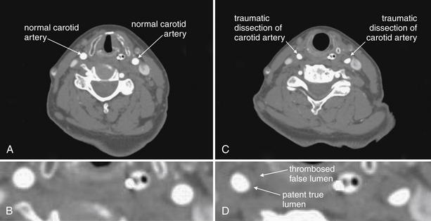
Figure 4-18 Vascular dissections (carotid artery).
This 75-year-old woman presented after a motor vehicle collision. The patient was noted to have an ecchymotic seat belt mark across her left neck. The patient had multiple other injuries, including a diaphragm injury diagnosed by chest x-ray, so CT angiography of the neck was prospectively planned (for assessment of cervical vascular injury) to be performed at the time of chest and abdominal CT to avoid repeating the intravenous contrast bolus. A, The normal carotid arteries below the level of the injury. Note the rounded appearance and bright filling with contrast B, a close-up view from A. C, Bilateral carotid artery dissections at the level of injury. The normal round appearance is replaced by a three-quarter moon appearance. The false lumen has thrombosed bilaterally, so an intimal flap is not seen (compare with aortic dissection in Chapter 7). D, a close-up view from C. In some cases, irregularity of the contour of the artery may be the only abnormal finding. The dissection has resulted in significant stenosis, approximately 30% to 40% on the left, and 20% to 30% on the right.
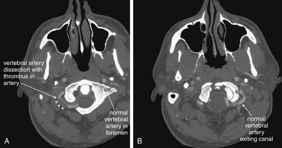
Figure 4-19 Vascular dissections (vertebral artery dissection): CT with IV contrast, viewed on vascular windows.
Spontaneous dissection of the vertebral artery is a relatively rare event but is thought to be one of the most common causes of stroke in young patients. Computed tomography (CT) angiography and magnetic resonance angiography are the most common methods of assessment today, with catheter-based angiography usually reserved for patients with CT or magnetic resonance abnormalities. Remember that the vertebral arteries exit their canals at the C1 level, curve medially, pass through the ring of C1, and then merge to form the basilar artery. In these axial CT images, IV contrast has been administered to the patient. The window level is set to an intermediate value between bone and soft-tissue settings. You can recognize this from the subcutaneous fat, which is not nearly black, and bone, which is too bright to allow its internal structure to be easily recognized. A, The left vertebral artery is seen within its canal. The curving right vertebral artery is seen with a filling defect representing a thrombosed region of dissection. B, The normal left vertebral artery is seen filled with contrast.
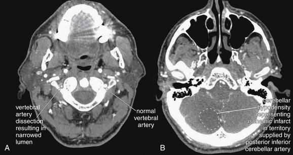
Figure 4-20 Vertebral artery dissection from C4 to C1 with posterior inferior cerebellar artery (PICA) territory infarct after cough.
This patient presented with vertigo after paroxysmal cough, and a cervical computed tomography angiogram was performed to evaluate for vertebral artery dissection. A, The left vertebral artery is of normal caliber. The right vertebral artery is narrowed to a fraction of the normal size. Is this a normal variant or acute disease? In congenital hypoplasia of the vertebral artery, the bony canal also is smaller than normal, whereas in this patient the canal is of normal size, indicating that the artery has an acute abnormality. B, A corresponding acute ischemic infarct is seen in the cerebellum in a region supplied by the PICA. Magnetic resonance imaging or magnetic resonance angiography could be used to provide similar information.
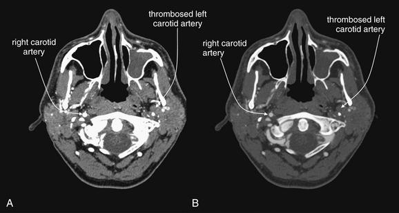
Figure 4-21 Carotid artery thrombosis.
This 47-year-old man presented with headache and underwent computed tomography venography of the head and neck to assess for venous sinus thrombosis. Instead, complete occlusion of the left internal carotid artery was discovered. A, Soft-tissue windows. B, A window setting similar to bone windows often used for assessment of vascular structures. The benefit of this window setting is that the internal structure of blood vessels, such as intimal tears, irregularity, or thrombosis is more evident. On typical soft-tissue windows (A), contrast in the vessel is so bright that internal structural detail is often less visible. In this particular case, the pathology is subtle for a different reason—you must recognize the absence of a normal structure in the image. Use expected symmetry to help you. The right carotid artery is well opacified with intravenous contrast. The left carotid artery is devoid of contrast because it has completely thrombosed. On a picture archiving and communication system, follow blood vessels through multiple slices to inspect them. Incidentally, the patient’s left maxillary sinus is opacified, suggesting sinusitis (see Chapter 2 for more information).
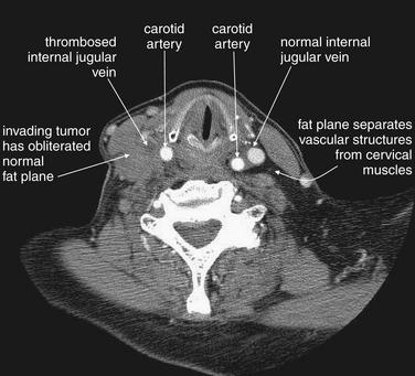
Figure 4-22 Internal jugular vein occlusion, CT with IV contrast, soft tissue windows.
This patient with an aggressive esophageal tumor has cervical adenopathy resulting from tumor metastases. The enlarging tumor burden has created local mass effect on the right internal jugular vein, which has become thrombosed as a result. The internal jugular contains dark thrombus on the right, compared with the bright contrast–filled left internal jugular vein. The cervical fat planes on the right have become obscured by invading tumor.
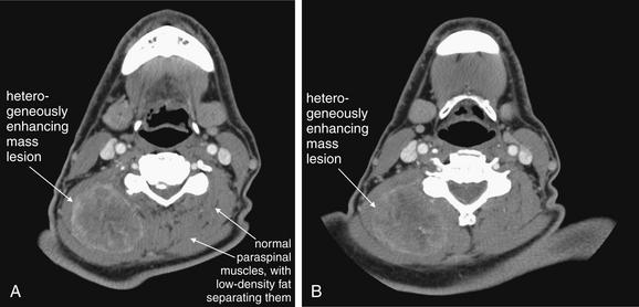
This 70-year-old patient presented with progressive right posterior neck swelling over a period of 1 month following a dental procedure. Asymmetry and a palpable mass were present on exam. Computed tomography (CT) with intravenous contrast was performed to assess for abscess or mass. A heterogeneously enhancing mass is visible in the right posterior paraspinous muscles, measuring approximately 5.2 by 4.2 cm in axial dimension. The mass does not have the appearance of an abscess, which most often would have a lower density (fluid density, darker gray) center. Note how the mass has obliterated the normal planes separating paraspinal muscles—compare this with the patient’s left side, which is normal. Without contrast, these asymmetrical features and the overall size of the mass would be appreciated, but the discrete margins of the mass would not be seen without enhancement because the mass shares the same density with normal muscle. CT does not identify the exact etiology of the mass, although the differential diagnosis for a muscle-density mass lesion includes sarcoma. Biopsy or excision would be needed to prove the diagnosis. Interestingly, the patient underwent fine-needle aspiration that showed gram-negative rods and spindle-shaped cells initially thought to represent reactive myositis or fasciitis—possibly an infection caused by the reported dental procedure. Unfortunately, surgical pathology showed an undifferentiated sarcoma.
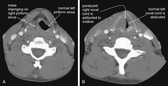
Figure 4-24 Neck masses: Laryngeal cancer with vocal cord paralysis, CT with intravenous contrast.
This patient has a laryngeal mass with complete paralysis of the right vocal cord. A, The mass occupies and obscures the left piriform sinus. Without a history of cancer, this appearance could be similar to a soft-tissue infection adjacent to the airway. B, The right vocal cord is completely paralyzed and is therefore is passively adducted to the midline. The left vocal cord is not paralyzed and is thus abducted normally.
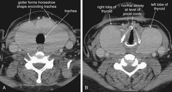
Figure 4-25 Goiter in Grave’s disease.
This 44-year-old woman with Graves disease complained of sore throat and a choking sensation. Computed tomography (CT) with intravenous (IV) contrast was performed. A large goiter surrounds the patient’s trachea but does not impinge upon it (A, B). CT is useful in the evaluation of thyroid masses, because it can simultaneously evaluate for airway impingement and mediastinal extension of a thyroid mass. In cases of thyroid malignancy, local invasion and metastatic disease can be detected. Rarely, IV contrast agents such as iodixanol (Visipaque) have been reported to precipitate thyroid storm in patients with hyperthyroidism. In addition, iodixanol may interfere with thyroid function determination by altering serum protein–bound iodine concentrations for up to 16 days. Therefore blood for thyroid function tests should be obtained before contrast administration.
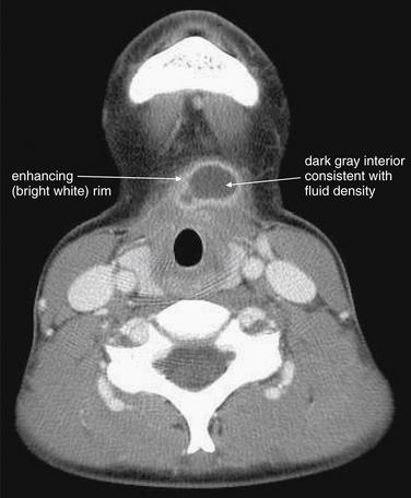
Figure 4-26 Thyroglossal duct cyst: Computed tomography (CT) with intravenous contrast, soft-tissue windows.
This patient presented with midline anterior cervical swelling, redness, and pain. Exam suggested an infected thyroglossal duct cyst, confirmed by the CT.
The CT reveals a well-demarcated, rounded cystic structure with rim enhancement. The midline position is typical of a thyroglossal duct cyst, an anatomic remnant that can become superinfected and rapidly enlarge. Treatment is usually with antibiotics, followed by definitive surgical excision. Rim enhancement is typical of an inflammatory or infectious process. The dark gray internal appearance is consistent with fluid density. The sharp margins of this structure are more consistent with a preexisting cyst than with an infectious abscess.
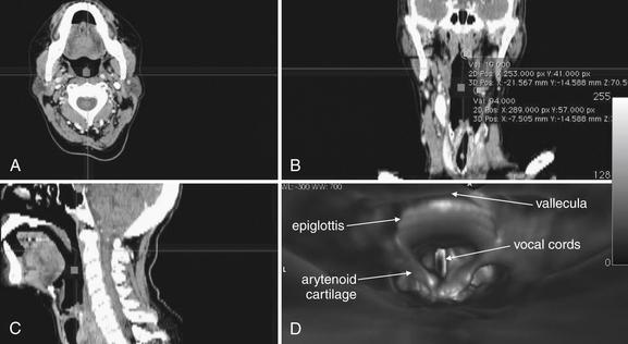
Figure 4-27 Computed tomography (CT) virtual laryngoscopy or bronchoscopy.
Modern thin-slice multidetector CT can be used to assess the airway in axial (A), coronal (B), sagittal (C), or three-dimensional (D) reconstructions. These images show a patient’s airway from several supraglottic views. The crosshairs in A through C indicate the planes displayed in the other two-dimensional images. For example, the horizontal line in A indicates the coronal plane displayed in B. The horizontal line in C indicates the axial plane displayed in A. The vertical line in B indicates the sagittal plane shown in C. D is a three-dimensional view of the epiglottis, arytenoid cartilages, and vocal cords seen from the point of view of an observer located at the square in the other images. Software packages synchronize the four views so that changes made in one image are reflected in the other views. Renderings of this type can provide information similar to laryngoscopy or bronchoscopy, but beware of airway collapse while the patient is positioned supine for CT. CT also provides no therapeutic option.
Focus on CT Window Settings: What Is a Window?
A window setting (Figure 4-28) is a method of distributing the available gray shades on CT to emphasize a particular tissue. A window is defined by two Hounsfield density values: a center value (also called “window level,” the tissue density that receives the middle gray shade in the available spectrum) and a width that defines the upper and lower tissue densities (which are colored white and black, respectively). Any tissue with a density lower than the lower limit of the window appears black. Any tissue with a density higher than the upper limit of the window appears white. The available gray shades from pure black to pure white are then evenly distributed among the densities within the window width. As a consequence, a narrow window setting allows fine differentiation of density differences surrounding the “center” value, but the ability to distinguish tissues above or below the window width is lost. Some typical window settings are shown in Table 4-2. Standard window settings optimized for evaluation of soft tissues, lung, bone, or vascular abnormalities are often preset on a digital PACS, although the user can vary the window settings or even save personalized settings.
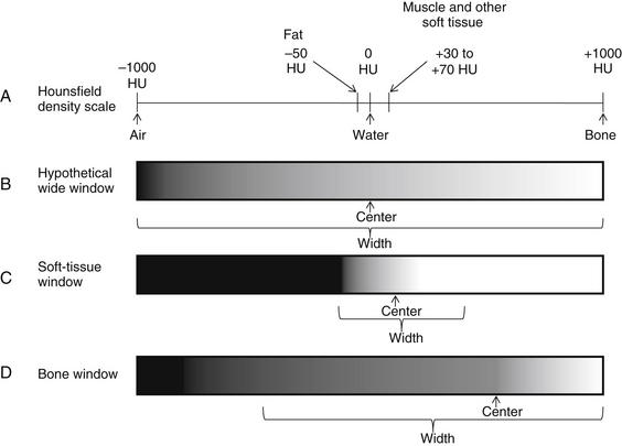
Figure 4-28 The Hounsfield CT density scale and CT windows
A, Each tissue has a fixed density on the Hounsfield scale, measured in Hounsfield units (HU). Air is defined as –1000HU. Water is defined as 0 HU. Densest bone is defined as +1000HU. Other tissues fall on the scale according to their relative densities. Although the density of a tissue is a fixed physical property, the appearance on CT depends on the window setting, which can be adjusted to accentuate a given range of densities. A window is defined by a center value, the density that is assigned the central gray shade in the available spectrum, and a width, which defines the densities on each side of the center that are assigned pure black and pure white. B, Hypothetical window centered on water density and distributing gray shades across the entire Hounsfield scale. On this setting, fine differences in density among body tissues from fat to water to muscle would be impossible to recognize, as all would be intermediate gray colors. C, Soft-tissue window centered on a soft tissue density around 50HU and distributing gray shades more narrowly, focusing on the range of densities representing most body soft tissues. On this window setting, fine differences in soft-tissue densities can be seen, but subtleties in very low density and very high density tissues are completely lost. D, Bone window centered on a density around 500HU and distributing gray shades across the range of densities representing bone. On this window setting, fine differences in bone densities can be seen. Soft tissues cannot be distinguished, as all share a dark gray color. Air can be distinguished from soft tissues on this window, as it appears completely black.
TABLE 4.2 Window Settings for CT
| Brain | 42 | 155 |
|---|---|---|
| Bone | 570 | 3077 |
| Lung | –498 | 1465 |
| Soft tissue (used for most neck structures, also used for chest and abdomen) | 56 | 342 |
Tissues with a density matching the center value are assigned the middle gray hue in the available range. The window width defines the tissue densities that will be assigned pure black and pure white. The center value plus one-half the width is assigned pure white. All tissues with this density or greater appear white. The center value minus one-half the width is assigned pure black. All tissues with this density or less appear black. The available gray shades are evenly distributed among tissues between these two extremes. Window settings can be adjusted by users, and no standards exist. The precise values used may vary among institutions and even among different CT readers. The values in this table are from the author’s institution.
What Is the CT Technique for Soft-Tissue Evaluation? Does It Differ from Cervical Spine CT?
CT for evaluation of soft tissues of the neck differs from CT for evaluation of the cervical spine. Cervical spine CT is performed without IV contrast, as bony injury can be seen without contrast material. For soft-tissue evaluation, IV contrast is given, as it reveals vascular abnormalities such as intimal tears or active bleeding (marked by contrast extravasation). In addition, infectious processes such as abscess and inflammatory or neoplastic conditions enhance with IV contrast, improving their detection and characterization. If IV contrast is contraindicated because of renal insufficiency or allergy, noncontrast CT can still provide important information, but evaluation of vascular pathology such as dissection and subtle infectious or neoplastic process will be insensitive. In this case, other modalities such as ultrasound may be needed.
The cephalad–caudad scope and field of view of soft-tissue neck CT also differ from those of cervical spine CT. Typically, cervical spine CT is performed from the skull base to the bottom of the T1 vertebral body. This usually captures the lung apices, although the reconstructed image is usually “coned in” so that only the spine, not the full diameter of the neck and chest, is seen. Usually, soft-tissue neck CT spans from the skull base to the top of the aortic arch to capture the carotid and vertebral arteries as they emerge from the aortic arch. This also allows assessment of prevertebral space abnormalities as they extend into the chest. The exact cephalad–caudad scope may vary from institution to institution and based on clinical indication—for example, the CT protocol for soft-tissue infection assessment may be different from the protocol for vascular assessment in some institutions. The field of view for soft tissue neck CT is usually broader than that for cervical spine CT, as the image is not “coned in.” Instead, soft tissue neck CT encompasses the entire diameter of the neck and any included regions of the chest.
Is Soft-Tissue Neck CT the Same as CT Cervical Angiography?
Cervical CT angiography overlaps substantially with other soft-tissue applications—at some institutions, the same CT protocol may be used. In cervical CT angiography, as with other CT angiography applications, a high-quality diagnostic study requires a rapid bolus of injected contrast material, properly timed with the CT acquisition to ensure that the bolus reaches the vascular bed of interest at the moment of image capture. For cervical CT angiography, this generally means a bolus of between 60 and 150 mL of iodinated contrast, administered at a rate of 4 mL per second. Automated bolus tracking software allows the CT technician to measure the enhancement of vessels such as the aortic arch (which leads directly to the cervical arteries) using a small test bolus. The necessary time delay from contrast injection until CT scan is then calculated. This time delay allows the contrast to transit from the peripheral vein, where it is injected; through the superior vena cava, right heart, and pulmonary vessels; and then to the left heart, where it is ejected through the aorta to the cervical vessels. Thin CT slices are obtained, and reconstructions in multiple planes are then used to inspect the vessels. Review of axial slices alone can be quite useful. CT venography of the neck uses the same technique as CT arteriography, but image acquisition is timed to coincide with the arrival of contrast in neck veins. By chance, often the image acquisition may occur when both arteries and veins are opacified with contrast. If evaluation of neck veins is the primary indication for imaging, ultrasound may be a better first choice, as it does not require radiation exposure or contrast administration. Soft-tissue cervical CT can be performed with a slower contrast bolus for evaluation of soft-tissue masses and infections, as the diagnosis is less reliant on dense opacification of blood vessels.
Approach to Interpretation of Soft-Tissue Neck CT
The large number of anatomic structures visible on soft-tissue neck CT makes a systematic approach to interpretation both essential and difficult. For most emergency applications, a soft-tissue window setting is appropriate, with exceptions pointed out in the figures. A simple approach is to select a structure with suspected pathology, such as a carotid artery, and follow that single structure from the cephalad to caudad limits of the scan, inspecting for abnormalities. The opposite side often provides an excellent normal example for comparison, as the neck is usually bilaterally symmetrical until the intersection of cervical vascular structures with great vessels in the chest. As is our habit for a FAST examination, apply a structured clinical question: Is a dissection of the carotid artery present? Is the airway narrowed? Is the palpable mass on examination an abscess? Often, CT is ordered by the emergency physician with a binary question of this type in mind. For the radiologist, the task is more difficult, as all structures in the field of view must be inspected. For the emergency physician, a targeted inspection based on the differential diagnosis usually provides the immediately clinically relevant information. In cases of trauma or when a particularly broad differential diagnosis is being entertained, systematic inspection of all cervical structures, rather than selective inspection, is crucial.
Cervical Soft-Tissue Ultrasound
Ultrasound is excellent for distinguishing soft-tissue and fluid densities. Its utility in imaging soft tissues of the neck is limited by several factors. Sound waves are chaotically dispersed by air, disrupting the image; for this reason, air-filled structures in the neck (trachea and, to a lesser degree, esophagus) obstruct imaging of deeper structures. In addition, bone is sufficiently dense that it reflects or absorbs essentially all sound waves, preventing imaging of deeper structures. As a consequence, ultrasound can be valuable for imaging relatively superficial neck structures and differentiating solid and cystic masses. It is advantageous in that it does not involve ionizing radiation or contrast administration.
Ultrasound can detect vascular dissections and stenoses of the carotid arteries and thrombosis of cervical venous structures (Figures 4-29 to 4-31). The vertebral arteries, partially hidden in the bony transverse foramina of the vertebral bodies (see Chapter 3), cannot be completely imaged with ultrasound, although portions can be assessed—in general, CT angiography or magnetic resonance angiography (MRA) is a better choice for evaluation of suspected vertebral artery pathology. Ultrasound is also limited in imaging the carotid arteries and cervical veins once those structures enter the skull base or chest; CT is not limited in this way.
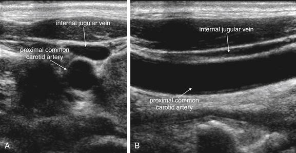
Figure 4-29 Normal carotid artery ultrasound.
Ultrasound is useful in assessment of the carotid arteries and internal jugular veins. It can detect carotid stenosis with high sensitivity and can be used to assess for vascular dissection. Thrombosis of the internal jugular veins or carotid arteries can also be detected. Ultrasound has become a standard tool in the placement of internal jugular central venous catheters—the figures above illustrate why ultrasound can be invaluable in preventing accidentally puncture of the carotid artery. Anatomy textbooks show the carotid artery lying medial to the internal jugular vein. In this patient, however, the internal jugular vein lies superficial to the carotid artery, not medial to it. The internal jugular vein is compressible and often appears elliptic or even polygonal in short-axis cross section. The carotid artery is far less compressible and has a circular short-axis cross section. A, Short-axis (transverse) view. B, Long-axis (longitudinal) view.
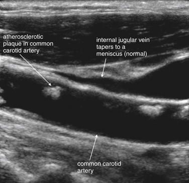
Figure 4-30 Carotid stenosis ultrasound (long-axis view).
Ultrasound can reveal carotid stenosis. Plaques can be directly visualized, and flow velocity can be measured to allow quantitative assessment of the degree of stenosis. Here, plaques are visible in the common carotid artery. The internal jugular vein is also visible and appears to taper to a point at its cephalad end, as the patient does not have elevated right heart pressures that would result in jugular venous distension. The distance from the sternal notch to the point of tapering of the internal jugular vein has also been described as a method of assessing such distension in obese patients.
Another appropriate use for ultrasound is in the evaluation of a palpable neck mass (Figures 4-32 to 4-34). Ultrasound can distinguish solid masses, which may suggest adenopathy or neoplasm, from fluid-filled structures such as cysts, abscesses, hematomas, and vascular anomalies. Examples of typical pathology of this type include thyroglossal duct cysts (see Figure 4-34), branchial cleft cysts, and goiters (see Figure 4-32). Ultrasound does not always distinguish reliably between benign and malignant lesions, so additional workup with biopsy is prudent.
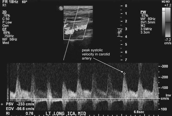
Figure 4-31 Severe carotid stenosis.
Quantitative ultrasound measurement of flow in the carotid artery allows assessment of degree of stenosis. As blood flows past a stenotic region, the velocity actually increases, measured as the peak systolic velocity (PSV). The patient’s measured value is compared to known normal and abnormal tabulated values to yield an estimate of stenosis. Here, the patient’s PSV is 233 cm/sec, which corresponds to stenosis of greater than 70%. The caption at the bottom of the figure was added by the ultrasonographer to indicate that this image is of the midportion of the left internal carotid artery, taken in long-axis cross section. Computed tomography angiography and magnetic resonance angiography can also provide quantitative values of stenosis based on vessel short-axis cross-sectional measurements.
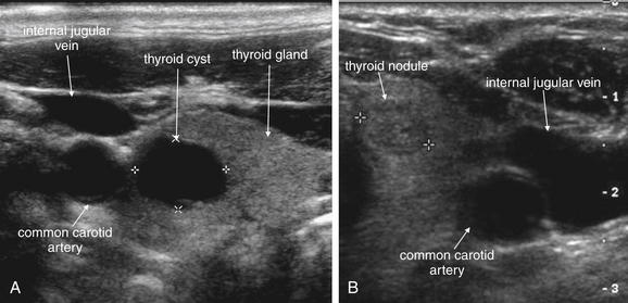
Figure 4-32 Thyroid cysts and nodules on ultrasound (short-axis view).
Ultrasound is useful in assessment of superficial neck masses. It readily distinguishes cystic and solid lesions. Common examples are thyroid cysts (A) and nodules (B). The thyroid is seen medial to the carotid artery and internal jugular vein. Cysts and blood vessels may appear similar in short-axis cross section, but cysts remain round in long-axis cross section while blood vessels appear tubular. In addition, cysts have no flow using Doppler ultrasound.
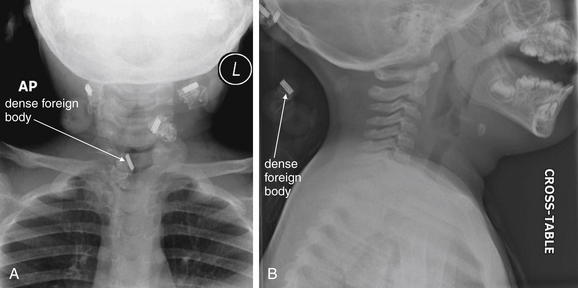
Figure 4-33 Foreign body or external object?
This healthy 2-year-old girl presented to the emergency department with a “lump” in the anterior neck for 2 days. On examination, a midline, 2-cm mass overlying the thyroid cartilage was noted. This was mobile with swallowing and elevated with tongue projection. It was minimally tender with slight erythema. This examination finding and the history of sudden appearance are consistent with an infected thyroglossal duct cyst. X-rays are not usually required, nor are they diagnostic, and ultrasound can be used to confirm the cystic nature of the mass (see Figure 4-33). In this case, x-rays were obtained, which serve two educational purposes. On the anterior–posterior (AP) view (A), dense objects are seen, one of which appears to overlie the airway. Is this an aspirated foreign body? On the lateral x-ray (B), this is seen to lie outside of the patient, behind the neck—a hair clip. In other words, these are normal pediatric soft-tissue neck x-rays. Always remove radiodense material from the patient before x-ray to avoid confusion and artifact. Review both AP and lateral projections to identify the location of objects.
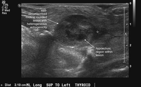
Figure 4-34 Infected thyroglossal duct cyst on ultrasound.
Same patient as Figure 4-33. Ultrasound confirms a well-circumscribed, midline, rounded structure. An uninfected thyroglossal duct cyst typically appears as a simple cyst, which on ultrasound has a uniform hypoechoic (black) center. This lesion has internal septations and is only partially hypoechoic, with a heterogeneous appearance. This is typical of infection. The patient underwent surgical excision that confirmed the diagnosis.
Doppler ultrasound can be used to assess for flow in fluid-filled structures. Ultrasound can detect air in cervical soft tissues, because the ultrasound image is unexpectedly disrupted by air interfering with sound transmission. When the pathology of concern would be expected to lie deep to air-filled or bony structures, or when evaluation of the cephalad and caudad extent of the pathology would require cranial or chest imaging, CT is generally a better imaging choice. Ultrasound remains a good alternative in young patients because of radiation concerns.
Soft-Tissue Neck Magnetic Resonance Imaging
MRI remains the test of choice for imaging of the cervical spinal cord, as well as ligaments and intervertebral discs of the cervical spine. This indication is discussed in more detail in Chapter 3, whereas other applications of MRI of the neck are discussed here. MRI provides exceptional soft-tissue contrast and comparable resolution of vascular pathology to CT. It can be used to image thoracic and cranial structures, making it particularly useful when vascular dissections originating from the aortic arch and resulting in ischemic stroke are suspected. CT provides similar information in this setting, although MRI is more definitive for early brain ischemic changes and infarcts. MRI is relatively rarely used in the emergency department for cervical imaging because it is less readily available, more expensive, and more time consuming than CT, which provides similar information for most clinical purposes. MRI does not involve ionizing radiation, an advantage over CT, which does. In the past, MRI was recommended for patients with renal insufficiency due to concerns about contrast nephropathy from iodinated contrast used in CT. However, recently described gadolinium-associated nephrogenic systemic fibrosis in patients with renal insufficiency has limited the use of MRI in this population. Nephrogenic systemic fibrosis is described in more detail in Chapter 15. MRI remains a good alternative in patients with iodine allergy who require cervical soft-tissue imaging with contrast.
A few principles of MRI bear emphasis here. MRI relies on the presence of protons to resonate in an applied magnetic field, providing a signal that is used to generate an image. Calcified bone does not have free protons to resonate in this way, so bone cortex lacks signal and appears black on all magnetic resonance sequences. For this reason, cortical bone fractures are not seen directly with MRI, although their presence is often inferred from associated soft tissue changes. Consequently, CT is the preferred modality for detection of cervical spine fracture. In contrast, bone marrow contains fat and is proton rich, providing a signal for detecting pathologic processes such as osteomyelitis and bone tumors. Air also lacks protons and does not generate a signal, although the absence of signal can be used to detect pathologic air in areas that would normally generate a soft-tissue signal. Even without the administration of gadolinium contrast, MRI thus often provides more information about soft tissues than does unenhanced CT scan, which cannot distinguish tissues that share the same physical density. CT with IV contrast can distinguish soft tissues with differing blood flow and enhancement characteristics, as described earlier in this chapter. MRI can readily detect differences in soft tissues based on differing signal characteristics from fat and water-containing soft tissues, both of which are rich in protons. MRI can be manipulated in different pulse sequences to allow differentiation of tissue types and forms of pathology. MRI pulse sequences are discussed in detail in Chapter 15. MR angiography (MRA) for assessment of vascular pathology is discussed later in this chapter, in comparison with CT angiography.
What Is the Best Strategy for Imaging of Airway Threats? Is Three-Dimensional CT Useful for Evaluation of Potential Penetrating Tracheal Injury?
Some general safety considerations guide soft-tissue neck imaging. Be extremely cautious in imaging of any patient with a threatened airway. This is obvious to us as emergency physicians, yet patients are frequently sent out of the emergency department for soft-tissue imaging when dyspnea or stridor is part of the clinical presentation. Soft-tissue x-rays may be useful in the setting of the endangered airway, as they can be performed portably with the patient in a position of comfort (see Figures 4-1 to 4-3, 4-5, 4-8 to 4-9, 4-11, and 4-13 to 4-15). In contrast, CT scan requires transportation of the patient out of the emergency department and supine positioning for the duration of the scan, which can compromise an already threatened airway (see Figures 4-6 and 4-7). Throughout this chapter, we see examples of pathology on x-ray and CT that could seriously endanger a patient who has not been intubated orally, nasally, or by means of a surgical airway. If serious impairment of the airway is considered, think about protecting the airway before imaging. Bronchoscopic airway evaluation can provide key information about intrinsic airway edema, obstruction, or foreign bodies, as well as narrowing from extrinsic compression. Moreover, bronchoscopy may provide a therapeutic solution by fiberoptic intubation, whereas diagnostic imaging does not. Three-dimensional CT “virtual bronchoscopy” (see Figure 4-27) can be performed with excellent resolution—but at the expense of radiation exposure and without the ability to remove a foreign body, stent a stenotic airway, or obtain cultures or pathologic samples—all possible with real bronchoscopy. The role of three-dimensional CT in airway imaging remains to be defined. In patients with a low pretest probability of pathology, the cost and radiation exposure of CT may not be warranted. In patients with a high probability of pathology, bronchoscopy may be the more appropriate test. Particularly in the case of suspected pediatric foreign body aspiration, CT has been described as a sensitive and specific imaging modality, but radiation concerns may make bronchoscopy the better choice. The risks of sedation for bronchoscopy must be weighed against the radiation effect of CT. Recent case series and case reports have reported the utility of three-dimensional CT virtual bronchoscopy for detection of tracheal injuries and foreign bodies.3-7 However, the sensitivity of this technique is not yet well-established. Larger studies are required to validate the safety of this technique to replace diagnostic bronchoscopy.
How Can CT Be Made More Specific for Airway Abnormalities?
It can be frustrating to obtain a CT scan in a patient with a potential airway problem only to have the CT interpretation indicate uncertainty about the airway structures. Multiple dynamic air contrast techniques have been described for stenting the airway open during CT, using humming, puffed cheeks, or valsalva maneuvers by the patient. Some patients with acute airway problems may be unable to comply, but for the patient who can cooperate, these maneuvers may eliminate artifacts created by normal partial airway collapse in the supine position. True obstructing airway anomalies such as masses or abscesses would presumably remain, while physiologic collapse or “kissing” of airway mucosal surfaces would be prevented.8 A discussion with the radiologist and CT technicians regarding your differential diagnosis can assist in selection of the optimal technique.
When Should X-ray Be Performed? Should All Patients Undergo X-ray Before CT? When Is CT the Best Initial Test?
As discussed earlier, x-ray relies on the juxtaposition of tissues of differing density for diagnosis. When present, these findings can indicate pathology. When absent, they may not reliably exclude pathology. The pretest probability and differential diagnosis should be carefully considered. X-ray may be the appropriate initial test for unstable patients and possibly the only test if positive. If an ingested or aspirated radiopaque foreign body is the primary concern, x-ray may be the appropriate first (and possibly sole) test. In patients with a low pretest probability of disease, x-ray is potentially the only test needed, although arguably no testing may be required in this group. If a negative x-ray would not be trusted to rule out disease as a result of high pretest probability, or if additional imaging would be required to delineate pathology found on x-ray, consider skipping x-ray and obtaining CT as the initial imaging test. CT is also the appropriate first test, rather than x-ray, when the differential diagnosis includes pathology difficult or impossible to detect by x-ray, such as vascular dissection or soft-tissue mass.
If X-ray Is Negative, Should CT Be Performed?
Given the limited sensitivity of x-ray, if a high suspicion of a structural abnormality exists, additional imaging may be required after a normal x-ray. If the patient’s airway is thought to be safe, CT scan can be performed to assess with higher sensitivity and anatomic detail. If the pretest probability of disease is low, no further imaging may be required following a normal x-ray.
Does CT Scan Necessarily Need to Be Performed for Further Evaluation of All X-ray Abnormalities?
Not all abnormalities on x-ray require further imaging with CT. For example, airway foreign bodies may require no further imaging but rather endoscopic extraction. Metallic foreign bodies often create streak artifact on CT, limiting the additional value of CT (see Figure 4-12). Epiglottitis identified by x-ray (see Figure 4-9) generally does not require further delineation with CT scan (see Figure 4-10), and the patient may be endangered by supine positioning in CT. Treatment decisions for this condition do not require information from CT. Linear soft-tissue air may indicate pneumomediastinum, paratracheal or paraesophageal air, or air in the prevertebral space (see Figure 4-5). The clinical setting and suspected source of the air strongly determine the need for further imaging. For example, air in cervical soft tissues following cough or sneeze would generally not require CT for evaluation due to a predictably benign clinical course without intervention. Chest x-ray may be appropriate for evaluation of possible associated pneumothorax, but the anatomic detail provided by CT is quite unlikely to alter management. In contrast, soft-tissue air following vomiting could indicate esophageal perforation (Figure 4-35), and additional imaging to evaluate the esophagus may be appropriate. Fluoroscopy may be more useful than CT in this setting, though both can detect esophageal perforation as discussed later in this chapter.
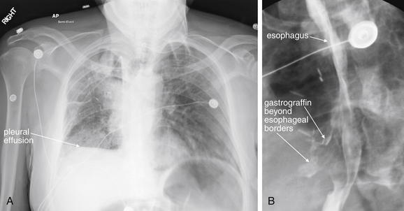
Figure 4-35 Esophageal perforation.
This 55-year-old patient with metastatic colon cancer and a history of mediastinal radiation therapy underwent esophageal stent placement and subsequent removal for treatment of a stricture. He presented to the emergency department with persistent coughing and emesis. A, The chest x-ray reveals a pleural effusion and possible right middle lobe infiltrate. B, An esophagram was performed because of concern for esophageal perforation. Gastrografin extravasation beyond the borders of esophagus proves esophageal perforation. In esophageal perforation, chest x-ray may show infiltrate, pleural effusions, pneumothorax, pneumomediastinum, or subcutaneous emphysema. Although less sensitive than barium swallow, Gastrografin swallow is the preferred initial study to confirm the diagnosis, because Gastrografin is less reactive than barium if leaked into the pleural space or mediastinum. If high suspicion remains despite a normal Gastrografin study, barium swallow or contrast-enhanced CT scan can be diagnostic.
How Sensitive Is X-ray to Rule Out Important Cervical Infections Such as Epiglottitis and Retropharyngeal Abscess? How Sensitive Is CT?
Classic x-ray findings of epiglottitis are quite specific but relatively insensitive. Therefore an abnormal x-ray rules in disease, but a normal x-ray may not rule out serious infection (Table 4-3). CT is sensitive and can identify complications such as local abscess formation, although supine positioning of the patient for CT can be hazardous. The patient should be carefully monitored if CT is performed.
TABLE 4-3 X-ray Findings of Epiglottitis in Adults
| X-ray Finding | Sensitivity (%) | Specificity (%) |
|---|---|---|
| Epiglottis width to AP width of C4 >0.33 | 96 | 100 |
| Prevertebral soft tissue–to–C4 ratio >0.5 | 37 | 100 |
| Width of hypopharyngeal airway to width of C4 >1.5 | 44 | 87 |
| Aryepiglottic fold enlargement | 85 | 100 |
| Arytenoid swelling | 70 | 100 |
From Nemzek WR, Katzberg RW, Van Slyke MA, et al. A reappraisal of the radiologic findings of acute inflammation of the epiglottis and supraglottic structures in adults. AJNR Am J Neuroradiol 16(3):495–502, 1995.
Lateral neck x-ray has a reported sensitivity of only about 80% for retropharyngeal abscess, while in some studies CT is reported to be 100% sensitive for soft-tissue abnormalities associated with retropharyngeal cellulitis and abscess.9-10 Other studies suggest that although CT identifies soft-tissue abnormalities, it is less useful in discriminating true abscess from soft-tissue infections that might resolve without surgical intervention. Compared with a criterion standard of surgical findings, CT was between 68% and 73.5% sensitive and 56% specific for abscess.11-12
Which Is Better for Detection of Retained Cervical Foreign Bodies, X-ray or CT?
X-ray is likely highly sensitive for retained metallic foreign body. However, less dense materials are variably detected by x-ray. In studies in which fish bones were placed into cadavers, providing a reliable criterion standard (as the number and location of foreign bodies were known), CT had a sensitivity of around 90%, compared with 39% for x-ray.13-14 Newer-generation CT scanners with thinner slice thickness may be even more sensitive and specific.
How Should Soft-Tissue Air from a Suspected Gastrointestinal Source Be Further Evaluated? Is CT or Fluoroscopy the Best Test? What Test Is Better for Esophageal Foreign Body?
If cervical soft-tissue air is seen following forceful vomiting, the patient may require evaluation for an esophageal tear—usually imaged with a fluoroscopic swallowing study (see Figure 4-35). CT can demonstrate esophageal thickening suggestive of esophagitis, and it may even demonstrate orally ingested contrast outside of the esophagus or a frank mediastinal infectious process.15-16 The decision to perform CT in this circumstance should be made after consideration of the differential diagnosis. If mediastinitis potentially requiring surgical intervention is considered, CT may be particularly useful. However, CT is a static study and does not demonstrate esophageal motility. Unlike CT of airway anatomy, virtual CT endoscopy of the esophagus is not generally useful because the esophagus is most often a potential space, not filled with air. Fluoroscopy can demonstrate detail of the mucosal folds of the esophagus and residual contrast left in partial- or full-thickness esophageal tears. Esophagram should be performed first with Gastrografin contrast material, as this material is less toxic to the mediastinal tissues if extravasation occurs. Gastrografin has low viscosity and may not cling to partial-thickness injuries. A normal Gastrografin study is usually followed by a fluoroscopic barium swallow study, because the more viscous material may demonstrate subtle injury. Fluoroscopy can also demonstrate retained esophageal foreign bodies and esophageal strictures (Figures 4-36 and 4-37).
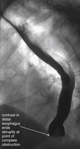
Figure 4-36 Esophageal steak foreign body, seen with fluoroscopy.
This 82-year-old patient with Crohn’s disease and a history of prior esophageal strictures presented with dysphagia after eating a steak 24 hours previously. He reported inability to swallow solids or liquids. A Gastrograffin swallow study was performed under fluoroscopy. An abrupt cutoff of contrast is seen in the distal esophagus, corresponding to complete obstruction. No contrast passes into the stomach. This fluoroscopic image does not reveal the cause of the obstruction, which could be due to a mass, stricture, or impacted food bolus. The patient underwent endoscopy that revealed a piece of steak lodged at the site of his prior strictures.
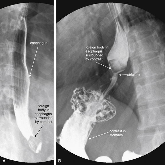
Figure 4-37 Food foreign body fluoroscopy.
This 38-year-old patient with no prior medical history complained of dysphagia and odynophagia since lunch the previous day. A and B, A barium swallow study under fluoroscopy was performed. It reveals a well-circumscribed foreign body in the distal esophagus measuring approximately 2 × 2 cm and having a quadrilateral shape. Some contrast does flow past the foreign body into the stomach. Distal to the foreign body is a narrow stream of contrast, suggesting a region of stricture or achalasia—likely the reason for the food impaction. Endoscopy did not reveal any lesions at this location. Incidentally, the patient also has a small hiatal hernia.
Is X-ray Useful in the Setting of Soft-Tissue Neck Trauma?
We discuss cervical spine imaging for trauma in detail in Chapter 3. Soft-tissue neck x-rays are generally not useful in blunt trauma patients with soft-tissue neck injuries, and the same cautions about airway protection discussed earlier apply. Most often, if serious soft-tissue injury from blunt trauma is suspected, CT scan is the most appropriate imaging test, as it can demonstrate even subtle cervical vascular injuries and abnormalities in prevertebral soft tissues. Esophageal injuries from blunt trauma are quite uncommon. Blunt traumatic airway injuries are more frequently directly examined with bronchoscopy, although as described earlier, CT is gaining an increasing foothold given the ability to perform multiplanar reconstructions and even three-dimensional virtual bronchoscopy (see Figure 4-27).
After penetrating trauma to the neck, x-rays are sometimes used for screening purposes if the patient is to go directly to the operating room for surgical exploration. X-ray in this case provides limited information about soft-tissue foreign bodies and extrinsic airway compression, as well as bony injury. In cases in which penetrating injury is thought to be superficial, x-rays sometimes demonstrate deep foreign bodies, indicating deep neck penetration requiring further evaluation, often with CT (see Figures 4-11 and 4-12).
How Does the Region of the Neck Injured Affect Imaging Strategy in Penetrating Trauma?
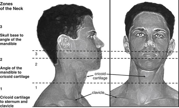
The neck is divided into three zones for purposes of evaluation following penetrating trauma, beginning with zone 1 inferiorly and progressing to zone 3 superiorly (Figure 4-38). Zone 1 extends from the thoracic inlet to the cricoid cartilage. It includes thoracic structures such as great vessels of the chest and neck, as well as the lung apices, trachea, esophagus, and cervical spine. Zone 2 extends from the cricoid cartilage to the angle of the mandible. It includes the carotid and vertebral arteries, jugular veins, larynx, pharynx, trachea, esophagus, thyroid gland, and cervical spine. Zone 3 extends from the angle of the mandible to the skull base. It includes the salivary and parotid glands, esophagus, trachea, vertebral bodies, jugular veins, carotid arteries, and major nerves (including cranial nerves IX through XII).
The neck is divided into three anatomic zones, which traditionally have directed diagnostic and therapeutic planning in penetrating neck trauma. Today, stable patients may be evaluated with computed tomography (CT) in many institutions, regardless of the zone injured. CT can detect vascular, airway, and esophageal injuries, though no high-quality prospective studies have evaluated CT against a criterion standard of endoscopic and surgical findings.
The imaging approach to the three neck zones was traditionally structured based on both the range of possible injuries and the ease of direct surgical exploration. Zone 1 injuries would require thoracotomy for complete surgical evaluation, so imaging traditionally played a significant role, including chest x-ray, aortography, esophagoscopy, and bronchoscopy. Zone 3 injuries are surgically difficult to access, because the mandible obscures structures as they approach the skull base. The traditional imaging approach included angiography, as well as endoscopic evaluation. Zone 2 injuries were more frequently directly explored, as surgical access was technically feasible and important injuries such as carotid artery injury were common.
Today, the diagnostic approach is simplified by CT. In unstable patients with obvious injuries, immediate operative intervention is often required and CT may be foregone in favor of surgical exploration. Examples would include a patient with a zone 1, 2, or 3 gunshot wound and hemodynamic instability. In the stable patient, CT can provide comprehensive evaluation including assessment of vascular, airway, and digestive tract injuries. A normal CT scan may eliminate the need for surgery or other imaging maneuvers, although this remains an area of controversy. CT abnormalities may require operative investigation or further imaging or direct visualization with endoscopy. We discussed CT of airway anomalies earlier in the chapter. Next we consider the performance of CT for evaluation of vascular pathology and esophageal injuries.
CT Evaluation of Cervical Vascular Injuries or Spontaneous Vascular Dissections
Spontaneous cervical artery (carotid and vertebral) dissection is thought to be a rare event yet is the most common cause of ischemic stroke in young adults, with 70% of cases occurring in patients in their 20s and 40s.17 Presenting symptoms include sudden, severe, and persistent neck pain, sometimes accompanied by headache. Neck pain alone occurs in about 25% of patients.18 Clinically, carotid and vertebral dissection may be indistinguishable unless an ischemic stroke results. Carotid artery dissections result in anterior circulation stroke symptoms, while vertebral artery dissection results in posterior circulation stroke. Both conditions can be evaluated by CT angiography or MRA. Carotid disease can also be evaluated by ultrasound, whereas the vertebral arteries are hidden within the transverse foramina of the cervical vertebrae and are not seen well with ultrasound. Blunt cervical arterial dissections can occur after major trauma, with the leading indications for imaging being known cervical spine fractures (especially high cervical injuries, subluxation, and fractures involving the transverse foramen; see Chapter 3) and neck hematomas or seat belt marks. Penetrating neck injuries, particularly zone 2 injuries, can result in carotid artery injuries. Some “spontaneous” cervical artery dissections may actually be the result of minimal trauma, such as cough, sexual activity, sporting activities, defecation, and chiropractic manipulation. In one series, 16% of “spontaneous” dissections occurred after chiropractic treatment.19 True spontaneous dissections with no apparent trauma are also described in the literature.19-27 Other risk factors include hypertension, tobacco use, connective tissue disorders, vasculitides, and migraines—the last being particularly unfortunate because of the potential overlap between symptoms of typical migraine and those of cervical artery dissection.
What History and Physical Examination Findings Suggest Cervical Artery Dissection? Can Physical Examination Rule Out a Vascular Problem?
Cervical artery dissections often present with headache, neck pain, or both, sometimes associated with ischemic symptoms developing hours or even days after the onset of neck pain. Delayed neurologic symptoms likely are the result of eventual thrombosis of the dissected segment, causing obstruction of flow, or embolization of thrombus from the dissected segment to intracranial arteries, resulting in stroke. An incomplete Horner’s syndrome (ptosis and miosis without anhydrosis) occurs in about 36% to 58% of patients, and lower cranial nerve palsies occur in less than 15%.17 In addition to headache or neck pain, vertebral artery dissection can present with posterior circulation stroke symptoms such as nausea or vomiting (53%), vertigo (57%), unilateral facial numbness (46%), gait disturbance (42%), diplopia (23%), dysphagia (11%), dysarthria (15%), or extremity paresthesias or weakness (11%).18 Symptoms can be transient, and neurologic deficits can be absent upon emergency department presentation, as transient ischemic attack may occur rather than frank stroke.
How Sensitive Is CT for Cervical Artery Dissection? How Does MRA Compare?
Cervical CT angiography (as described earlier) is the diagnostic test of choice for suspected cervical artery dissection in the emergency department. It is nearly 100% sensitive and specific when compared with conventional angiography; is widely available, rapid, and noninvasive; and can evaluate alternative diagnoses. Alternative diagnostic techniques include digital fluoroscopic cervical angiography (78% to 84% sensitive), vascular ultrasound, or MRI or MRA of the head and neck, which is more than 95% sensitive. CT angiography is subject to rare false-positive and false-negative results, sometimes for technical reasons such as poor contrast bolus, patient movement, failure to include the entire artery in question, or metallic streak artifacts in the image field. If significant suspicion for this diagnosis remains despite a normal CT angiogram (e.g., in the patient with neurologic deficits and a history of cervical trauma), consider further evaluation with MRA or formal angiography.28
How Large an Intravenous Catheter Is Needed for CT Cervical Angiography? Does It Matter Where It Is Placed? Can Central Venous Catheters Be Used?
Two issues limit the size, location, and type of IV catheter used for cervical CT angiography (and other CT angiography applications). First, the catheter must allow a rapid contrast bolus for a diagnostically adequate study. Second, the catheter must resist contrast extravasation or catheter embolization. Cervical CT angiography requires a rapid contrast bolus for a high-quality diagnostic study to be obtained. Within seconds, enough contrast has to be injected to opacify the cervical arteries, allowing a luminal defect within the vessel to be accurately characterized as a dissection, or for a stenotic region to be recognized. If the contrast bolus is too slow, the cervical arteries may be poorly opacified. This can lead to both false positives (an apparent filling defect, which is just normal fluid blood within the cervical arteries) and false negatives (actual dissections or other anomalies attributed to poor contrast bolus and unopacified blood). The protocol for cervical angiography studies may vary a bit from institution to institution, but published protocols call for injection rates of 4 to 5 mL per second. What are the flow tolerances of peripheral angiocatheters, the color-coded IV catheters used in most emergency departments? Take a look at the packaging during your next shift, and you will see the flow rate marked on the package. From physics, you will recall that the rate of flow is inversely proportional to the resistance; high resistance means low flow. The resistance is directly proportional to the length of the catheter, so a long catheter means high resistance and low flow. More importantly, the resistance is inversely proportional to the radius of the catheter, raised to the fourth power! So a small increase in radius means a substantial decrease in resistance and increase in flow. Translation: For fast flow, use the shortest, fattest catheter available. Some sample flow rates for a common vendor are shown in Table 4-4.
TABLE 4-4 Flow Rates Through Common Angiocatheters
| Catheter Size and Color | Rated Flow per Minute (mL) | Flow per Second (mL) |
|---|---|---|
| 24 g, 25 mm long (yellow) | 17 | 0.28 |
| 22 g, 25 mm long (blue) | 28 | 0.46 |
| 20 g, 48 mm long (pink) | 42 | 0.7 |
| 18 g, 48 mm long (green) | 79 | 1.3 |
| 16 g, 48 mm long (gray) | 147 | 2.45 |
| 14 g, 48 mm long (orange) | 277 | 4.6 |
∗Manufacturer’s Web site, Becton Dickinson (BD) peripheral IV.
These numbers reflect gravity flow rates, not flow through pressure injectors used for CT angiography. A phantom study using 14- through 24-gauge catheters showed adequate flow rates of 5 mL per second using 14-, 16-, 18-, and 20-gauge catheters. The 22-gauge catheters did not allow adequate flow because the safe pressure limit of 325 psi was reached at a lower flow rate. The 24-gauge catheter became disconnected because of high pressures.29
Recommended catheter location is driven by both flow rate and safety concerns. Generally, more peripheral placement of catheters may result in slower flow. Safety concerns exist for power injection through catheters placed in the neck (external jugular vein catheters), as contrast extravasation in this location can be particularly dangerous. Extravasated contrast can cause tissue necrosis, and in the neck it might pose threats to the airway, as well as critical vascular structures.
Triple lumen central venous catheters face the same issues described above as peripheral catheters—most have a single 16-gauge and two 18-gauge lumens, but the added length of the catheter means greater resistance and lower flow rates. Rare cases of central venous catheter fracture and embolization during injection exist, although most occur in the setting of long-term tunneled subclavian catheters, which may be pinched by bony structures.30-32 Some newer permanent and emergency devices are designed for high-pressure rapid infusion. Examples include PowerPort and PowerLine (Bard Access Systems) which can tolerate 300 psi with a maximum infusion rate of 5 mL per second (information from the manufacturer’s Web site).
Is CT Useful for Evaluation of Possible Esophageal and Tracheal Injury Following Penetrating Neck Trauma?
Given the utility of CT for evaluating potential vascular injuries following neck trauma, it would be particularly valuable if CT also offered adequate evaluation of the airway and esophagus. Traditionally, penetrating neck injuries often required multimodal evaluation with angiography, fluoroscopic swallow studies, and often both fiberoptic esophagoscopy and bronchoscopy. A study of 42 penetrating zone 2 neck trauma patients (including both stab and gunshot wounds) undergoing soft-tissue CT scan, esophagoscopy, and open neck exploration found that CT was equivalent to esophagoscopy for detection of esophageal stab wounds, but only 50% sensitive compared with surgical exploration. Patients received 250 mL of oral contrast before the CT exam, as well as IV contrast. CT detected four of seven internal jugular vein injuries (57%) identified during operative exploration. The authors concluded that CT is insensitive and added little to the evaluation of patients in whom neck exploration is planned. However, this study has several limitations. First, the confidence intervals on all results are limited by small numbers—only four esophageal injuries were found, and no carotid or airway injuries were present in the study group. Second, the study spans a period from 1997 to 2001 and used 5-mm CT slices. It is possible that more modern CT scanners with thinner slices would provide higher sensitivity.33 In addition, the more important clinical question may be, Can a negative CT be used to avoid neck exploration in lower-risk patients? Can it eliminate the need for endoscopic evaluation and swallow studies? Unfortunately, the small studies of this topic do not fully answer our questions. CT findings of esophageal perforation have been described, including periesophageal air, periesophageal fluid, esophageal wall thickening, esophageal wall laceration, and extravasation of oral contrast. The sensitivity and specificity of these findings are not well known.15,16,34 Despite a pavcity of good evidence, many trauma centers are beginning to rely on CT to exclude injuries and to defer additional studies in selected patients.
What Considerations Should Be Made in Selecting Patients for CT Evaluation of Suspected Neck Infection?
CT can be valuable in ruling out significant causes of neck pain, but unfortunately no clear clinical decision rules guide the need for cervical CT. Given the radiation exposure, CT should not be used to screen patients with a benign history and examination, although as we review later, many exam findings are insensitive. The emergency physician should carefully consider the differential diagnosis of the patient with neck pain to identify patients for whom CT should be employed. When cervical epidural abscess, diskitis, or osteomyelitis is considered, MRI is the test of choice, as discussed in Chapter 3.
A variety of significant infections within the skull base and neck may present with neck pain. These include peritonsillar, parapharyngeal, and retropharyngeal abscesses; epiglottitis; Ludwig’s angina; osteomyelitis; diskitis; and cervical epidural abscesses. Infections of congenital structures such as thyroglossal duct and branchial cleft cysts may occur. Infectious thrombophlebitis of the internal jugular vein (Lemierre’s syndrome) may present with neck pain and has high mortality if not aggressively treated. Deep cervical infections can spread to the mediastinum along fascial planes, resulting in mediastinitis with mortality as high as 60%.35
Although epiglottitis is rare in pediatric patients since the introduction of the Haemophilus influenzae vaccine in the 1990s, it continues to occur in adults at rates similar to those in the prevaccine era.36-37 Adult cases now outnumber pediatric cases by nearly five to one.38 Rarely, H. influenzae–related epiglottitis affects fully vaccinated children. A 10-year retrospective study identified 19 pediatric epiglottitis cases in a single children’s hospital, 6 positive for H. influenzae, and 5 of those 6 in fully vaccinated children.39 Epigottitis can be diagnosed by x-ray and CT (see Figures 4-9 and 4-10), although direct visualization with nasopharyngoscopy may be a better choice.
Injection drug users are at risk for cervical venous thrombosis and deep neck abscesses, including epidural spinal abscess. Retained needle fragments may be present and can result in abscess or pseudoaneurysm. Patients may not reveal cervical injection in 50% of cases,40-41 and cervical osteomyelitis is another complication of this practice (see Chapter 3).42-43 Ingested foreign bodies, including bone fragments and other sharp objects, may also cause deep space infection. Neck pain with neurologic complaints localizing to the cervical spine may indicate cervical epidural abscess. Distant infectious sources such as skin abscesses and urinary tract infection can spread hematogenously, resulting in deep cervical infections that include cervical epidural abscess. Minor preexisting abnormalities of the cervical spine may increase the risk for hematogenous seeding. Immune compromise from diseases such as diabetes mellitus, alcoholism, cancer, chronic renal failure, organ transplantation, and acquired immunodeficiency syndrome increases the risk of cervical epidural abscess. Prior invasive spinal procedures, even several months before presentation, should increase the suspicion of cervical epidural abscess. No identified risk factors are present in about 18% of cases.44-45
Are History and Physical Examination Reliable in Excluding Deep Neck Infection, Eliminating the Need for Imaging?
Unfortunately, physical examination and history are only moderately sensitive for deep neck infection. In a retrospective review comparing physical examination findings and symptoms with CT diagnosis of deep neck infection, the physical examination for deep cervical infections was insensitive, approaching 70%. Signs and symptoms suggesting deep infection were present with the following frequency: pain (89.2%), odynophagia (63.1%), dysphagia (47.7%), neck swelling (84.6%), fever (75.4%), local erythema (66.7%), and localized increase in temperature (55.4%).46 In epiglottitis, drooling occurs in only 15% of patients and stridor or dyspnea in only about 9%. Although “hot potato” voice may suggest epiglottitis,39 one study suggested that a muffled voice occurs in only about 50% of patients.47 Fever is an insensitive finding, occurring in between 30% and 80% of patients with cervical epidural abscess.44,48-49 The classic triad of fever, localized spinal tenderness, and progressive neurologic deficits occurs in only 37% of patients with cervical epidural abscess.50
Do Laboratory Tests Assist in the Diagnosis of Deep Space Cervical Infections, Identifying Patients Who Require Imaging?
In cervical epidural abscess, leukocytosis is present in only about 60% of patients.48 An elevated sedimentation rate is present in 95% of cases, although the mean value is only about 50 mm per hour. Because many conditions may elevate the sedimentation rate, reliance on this test may lead to unnecessary cervical imaging.48,51 Immune compromise may limit changes in white blood cell count and sedimentation rate, and their sensitivity in immunocompromised patients is not well studied.
When Should Imaging Be Considered for a Possible Cervical Mass?
Neck pain or swelling may be an indication of a cervical mass, including malignant (see Figures 4-23 and 4-24) and benign neoplasms (see Figure 4-25). Congenital abnormalities include thyroglossal duct cysts (see Figures 4-26 and 4-34) in the midline, and branchial cleft cysts in the lateral neck. Both can be occult until infection occurs, at which time pain, swelling, and erythema may develop. Malignancy should be suspected and imaging should be performed when weight loss, hoarseness, odynophagia or dysphagia, or neurologic symptoms such as ptosis are present. Some neoplasms such as lymphomas occur in younger patients, so young age should not provide false reassurance. However, cervical neoplasms increase in incidence with age, and imaging of older patients should be strongly considered. Metastatic squamous cell carcinoma occurs in up to 23.5% of patients over the age of 40 with solitary, benign-appearing cervical cysts.52 Alcohol use and cigarette smoking are risk factors.53 Not all imaging for possible malignancy need occur in the emergency department. If the airway is not threatened, the patient is able to tolerate oral food and drink, and other factors in history and physical examination do not suggest an infectious cause, outpatient follow-up for imaging may be appropriate.
Can History and Physical Examination Rule Out a Serious Neck Mass, Eliminating the Need for Imaging?
Unfortunately, history and examination findings have shown poor positive and negative predictive values for malignancy, between 60% and 80%.53 Factors such as progressive worsening over weeks or months and increasing number and size of lesions should raise suspicion.
Inspect the oropharynx for lesions, as oral cancers may spread locally or metastasize within the neck. Check the neck for asymmetry, and palpate the neck for anterior and posterior lymph nodes and abnormalities of the thyroid gland. Ask the patient about changes in voice, and listen for hoarseness. Although hoarseness can result from a benign diagnosis such as laryngitis, malignant involvement of the larynx and recurrent laryngeal nerve can also cause change in voice. Check the eyelid position and pupillary size and reactivity. Ptosis, miosis, and anhydrosis (Horner’s syndrome) can occur from malignant or benign compression of sympathetic nerves innervating the face. In the end, the insensitivity of history and exam for masses means that patients with a normal examination may require imaging for further diagnosis. However, this can occur if symptoms persist at follow-up, rather than in the emergency department.
Is Soft-Tissue Neck X-ray Useful in Evaluation for Neck Masses? What Other Imaging Can Be Helpful?
X-rays of the neck are insensitive for masses and not generally useful. If a mass is considered, CT with IV contrast has excellent sensitivity. CT delineates the extent of a mass, its density and vascular enhancement pattern, its mass effect on adjacent structures, and local invasion and metastasis. If the patient has contraindications to iodinated contrast, MRI may be used. Ultrasound can differentiate cystic from solid masses.54
Summary
Imaging of soft tissues of the neck requires careful consideration of the differential diagnosis to avoid unnecessary imaging in low-risk patients or imaging that does not positively influence management decisions. The broad list of soft-tissue pathology defies a simple clinical decision rule. CT is highly sensitive and specific for much of the important emergency pathology, but it carries a high radiation and economic cost and should not be ubiquitously applied. X-ray is insensitive and plays a limited role. Specialized tests such as contrast esophagram are indicated in selected patients.
1. Rojas C.A., Vermess D., Bertozzi J.C., et al. Normal thickness and appearance of the prevertebral soft tissues on multidetector CT. AJNR Am J Neuroradiol. 2009;30(1):136-141.
2. Chen M.Y., Bohrer S.P. Radiographic measurement of prevertebral soft tissue thickness on lateral radiographs of the neck. Skeletal Radiol. 1999;28(8):444-446.
3. Sodhi K.S., Saxena A.K., Singh M., et al. CT virtual bronchoscopy: new non invasive tool in pediatric patients with foreign body aspiration. Indian J Pediatr. 2008;75(5):511-513.
4. Huang H.J., Fang H.Y., Chen H.C., et al. Three-dimensional computed tomography for detection of tracheobronchial foreign body aspiration in children. Pediatr Surg Int. 2008;24(2):157-160.
5. Le Guen M., Beigelman C., Bouhemad B., et al. Chest computed tomography with multiplanar reformatted images for diagnosing traumatic bronchial rupture: A case report. Crit Care. 2007;11(5):R94.
6. Scaglione M., Romano S., Pinto A., et al. Acute tracheobronchial injuries: Impact of imaging on diagnosis and management implications. Eur J Radiol. 2006;59(3):336-343.
7. Moriwaki Y., Sugiyama M., Matsuda G., et al. Usefulness of the 3-dimensionally reconstructed computed tomography imaging for diagnosis of the site of tracheal injury (3D-tracheography). World J Surg. 2005;29(1):102-105.
8. Henrot P., Blum A., Toussaint B., et al. Dynamic maneuvers in local staging of head and neck malignancies with current imaging techniques: Principles and clinical applications. Radiographics. 2003;23(5):1201-1213.
9. Boucher C., Dorion D., Fisch C. Retropharyngeal abscesses: A clinical and radiologic correlation. J Otolaryngol. 1999;28(3):134-137.
10. Nagy M., Backstrom J. Comparison of the sensitivity of lateral neck radiographs and computed tomography scanning in pediatric deep-neck infections. Laryngoscope. 1999;109(5):775-779.
11. Stone M.E., Walner D.L., Koch B.L., et al. Correlation between computed tomography and surgical findings in retropharyngeal inflammatory processes in children. Int J Pediatr Otorhinolaryngol. 1999;49(2):121-125.
12. Vural C., Gungor A., Comerci S. Accuracy of computerized tomography in deep neck infections in the pediatric population. Am J Otolaryngol. 2003;24(3):143-148.
13. Palme C.E., Lowinger D., Petersen A.J. Fish bones at the cricopharyngeus: A comparison of plain-film radiology and computed tomography. Laryngoscope. 1999;109(12):1955-1958.
14. Lue A.J., Fang W.D., Manolidis S. Use of plain radiography and computed tomography to identify fish bone foreign bodies. Otolaryngol Head Neck Surg. 2000;123(4):435-438.
15. de Lutio di Castelguidone E., Merola S., Pinto A., et al. Esophageal injuries: Spectrum of multidetector row CT findings. Eur J Radiol. 2006;59(3):344-348.
16. Young C.A., Menias C.O., Bhalla S., et al. CT features of esophageal emergencies. Radiographics. 2008;28(6):1541-1553.
17. Lee W.W., Jensen E.R. Bilateral internal carotid artery dissection due to trivial trauma. J Emerg Med. 2000;19(1):35-41.
18. Saeed A.B., Shuaib A., Al-Sulaiti G., et al. Vertebral artery dissection: Warning symptoms, clinical features and prognosis in 26 patients. Can J Neurol Sci. 2000;27(4):292-296.
19. Dziewas R., Konrad C., Drager B., et al. Cervical artery dissection: Clinical features, risk factors, therapy and outcome in 126 patients. J Neurol. 2003;250(10):1179-1184.
20. Wessels T., Rottger C., Kaps M., et al. Upper cranial nerve palsy resulting from spontaneous carotid dissection. J Neurol. 2005;252(4):453-456.
21. Wessels T., Sparing R., Neuschaefer-Rube C., et al. Vocal cord palsy resulting from spontaneous carotid dissection. Laryngoscope. 2003;113(3):537-540.
22. Chiche L., Praquin B., Koskas F., et al. Spontaneous dissection of the extracranial vertebral artery: Indications and long-term outcome of surgical treatment. Ann Vasc Surg. 2005;19(1):5-10.
23. Guidetti D., Pisanello A., Glovanardi F., et al. Spontaneous carotid dissection presenting lower cranial nerve palsies. J Neurol Sci. 2001;184(2):203-207.
24. Rees J.H., Valentine A.R., Llewelyn J.G. Spontaneous bilateral carotid and vertebral artery dissection presenting as a Collet-Sicard syndrome. Br J Radiol. 1997;70(836):856-858.
25. Silbert P.L., Mokri B., Schievink W.I. Headache and neck pain in spontaneous internal carotid and vertebral artery dissections. Neurology. 1995;45(8):1517-1522.
26. Mokri B., Houser O.W., Sandok B.A., et al. Spontaneous dissections of the vertebral arteries. Neurology. 1988;38(6):880-885.
27. Mokri B., Schievink W.I., Olsen K.D., et al. Spontaneous dissection of the cervical internal carotid artery: Presentation with lower cranial nerve palsies. Arch Otolaryngol Head Neck Surg. 1992;118(4):431-435.
28. Munera F., Soto J.A., Nunez D. Penetrating injuries of the neck and the increasing role of CTA. Emerg Radiol. 2004;10(6):303-309.
29. Behrendt F.F., Bruners F., Keil S., et al. Impact of different vein catheter sizes for mechanical power injection in CT: In vitro evaluation with use of a circulation phantom. Cardiovasc Intervent Radiol. 2009;32(1):25-31.
30. Chawla L.S., Chegini S., Thomas J.W., et al. Hemodialysis central venous catheter tip fracture with embolization into the pulmonary artery. Am J Kidney Dis. 2001;38(6):1311-1315.
31. Coles C.E., Whitear W.P., Le Vay J.H. Spontaneous fracture and embolization of a central venous catheter: Prevention and early detection. Clin Oncol (R Coll Radiol). 1998;10(6):412-414.
32. Talwar V., Pavithran K., Vaid A.K., et al. Spontaneous fracture and pulmonary embolization of a central venous catheter. J Vasc Access. 2003;4(4):158-159.
33. Gonzalez R.P., Falimirski M., Holevar M.R., et al. Penetrating zone II neck injury: Does dynamic computed tomographic scan contribute to the diagnostic sensitivity of physical examination for surgically significant injury? A prospective blinded study. J Trauma. 2003;54(1):61-64. discussion 64-65
34. LeBlang S.D., Nunez D.B.Jr. Helical CT of cervical spine and soft tissue injuries of the neck. Radiol Clin North Am. 1999;37(3):515-532. v-vi
35. Cardenas-Malta K.R., Cortes-Flores A.O., Fuentes-Orous L., et al. [Necrotizing mediastinitis in deep neck infections]. Cir Cir. 2005;73(4):263-267.
36. McVernon J., Trotter C.L., Slack M.P., et al. Trends in Haemophilus influenzae type B infections in adults in England and Wales: surveillance study. BMJ. 2004;329(7467):655-658.
37. Berger G., Landan T., Berger S., et al. The rising incidence of adult acute epiglottitis and epiglottic abscess. Am J Otolaryngol. 2003;24(6):374-383.
38. Wood N., Menzies R., McIntyre P. Epiglottitis in Sydney before and after the introduction of vaccination against Haemophilus influenzae type B disease. Intern Med J. 2005;35(9):530-535.
39. Shah R.K., Roberson D.W., Jones D.T. Epiglottitis in the Hemophilus influenzae type B vaccine era: Changing trends. Laryngoscope. 2004;114(3):557-560.
40. Williams M.F., Eisele D.W., Wyatt S.H. Neck needle foreign bodies in intravenous drug abusers. Laryngoscope. 1993;103(1):59-63.
41. Myers E.M., Kirkland L.S.Jr., Mickey R. The head and neck sequelae of cervical intravenous drug abuse. Laryngoscope. 1988;98(2):213-218.
42. Smith M.A., Trowers N.R., Klein R.S. Cervical osteomyelitis caused by Pseudomonas cepacia in an intravenous-drug abuser. J Clin Microbiol. 1985;21(3):445-446.
43. Sapico F.L., Montgomerie J.Z. Vertebral osteomyelitis in intravenous drug abusers: Report of three cases and review of the literature. Rev Infect Dis. 1980;2(2):196-206.
44. Darouiche R.O., Hamill R.J., Greenberg S.B., et al. Bacterial spinal epidural abscess: Review of 43 cases and literature survey. Medicine (Baltimore). 1992;71(6):369-385.
45. Ravicovitch M.A., Spallone A. Spinal epidural abscesses: Surgical and parasurgical management. Eur Neurol. 1982;21(5):347-357.
46. Crespo A.N., Chone C.T., Fonseca A.S., et al. Clinical versus computed tomography evaluation in the diagnosis and management of deep neck infection. Sao Paulo Med J. 2004;122(6):259-263.
47. Chang Y.L., Lo S.H., Wang P.C., et al. Adult acute epiglottitis: Experiences in a Taiwanese setting. Otolaryngol Head Neck Surg. 2005;132(5):689-693.
48. Rigamonti D., Liem L., Sampath P., et al. Spinal epidural abscess: Contemporary trends in etiology, evaluation, and management. Surg Neurol. 1999;52(2):189-196. discussion 197
49. Redekop G.J., Del Maestro R.F. Diagnosis and management of spinal epidural abscess. Can J Neurol Sci. 1992;19(2):180-187.
50. Ekbom D.C., D-Ella J., Isaacson B., et al. Spinal epidural abscess after cervical pharyngoesophageal dilation. Head Neck. 2005;27(6):543-548.
51. Wong D., Raymond N.J. Spinal epidural abscess. N Z Med J. 1998;111(1073):345-347.
52. Gourin C.G., Johnson J.T. Incidence of unsuspected metastases in lateral cervical cysts. Laryngoscope. 2000;110(10):1637-1641.
53. Bhattacharyya N. Predictive factors for neoplasia and malignancy in a neck mass. Arch Otolaryngol Head Neck Surg. 1999;125(3):303-307.
54. Gritzmann N., Hollerweger A., Macheiner P., et al. Sonography of soft tissue masses of the neck. J Clin Ultrasound. 2002;30(6):356-373.