Chapter 3 Imaging the Cervical, Thoracic, and Lumbar Spine
In this chapter, we discuss imaging of the cervical, thoracic, and lumbar spine. Although differences exist, many common themes are shared in both the selection and the interpretation of diagnostic studies for all regions of the spine. Our discussion of all spinal regions starts with interpretation of images, with a focus on computed tomography (CT) scan. We correlate CT findings with x-ray when possible, and we demonstrate associated soft-tissue abnormalities identified on magnetic resonance imaging (MRI). Don’t be daunted by the number of figures in this chapter—we explore injuries and nontraumatic spinal pathology in many imaging planes and in multiple modalities to maximize your three-dimensional understanding. The figure captions are designed to allow the figures to stand alone, so we spend relatively little time discussing specific fracture patterns in the text. The figures in the chapter span a range of important spinal pathology, moving from cephalad to caudad. The list in Table 3-1 can guide you to the relevant figure, where diagnostic features are discussed in detail.
TABLE 3-1 Imaging Findings and Related Figure Numbers
| Content | Figure Number |
|---|---|
| Three-dimensional CT reconstructions of the normal cervical spine | 3-1 through 3-7 |
| X-rays of the normal cervical spine | |
| Normal sagittal CT views | 3-19 and 3-20 |
| Normal coronal CT view | 3-21 |
| Normal axial view | 3-22 |
| Occipital condyle fractures | 3-24 through 3-27 |
| C1 burst (Jefferson) fractures | 3-28 through 3-31 |
| Atlantoaxial (C1-C2) rotary fixations | 3-32 through 3-38 |
| C1 posterior arch fracture | 3-39 |
| C2 dens fractures, type II | 3-40 through 3-43 |
| C2 dens fractures, type III | 3-44 through 3-48 |
| Hangman’s fractures of C2 | 3-49 through 3-57 |
| Transverse process fractures | 3-58 and 3-98 |
| Cervical burst compression fractures | 3-59 through 3-62 |
| Teardrop flexion fractures | 3-63 through 3-66 |
| Jumped facets, bilateral and unilateral | 3-67 through 3-75 |
| Cervical facet fractures with spinal cord injury on MRI | 3-76 and 3-77 |
| Cervical lamina fractures | 3-78 through 3-80 |
| Acute cervical ligamentous injuries with x-ray, CT, and MRI findings | 3-81 through 3-84 |
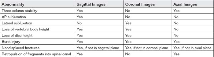
| Three-column concept of spinal stability | 3-85 |
| T2 corner avulsion fractures (extension teardrop) | 3-86 and 3-87 |
| Thoracolumbar compression and burst fractures | 3-88 through 3-101 |
| Chance fractures | 3-99 through 3-101 |
| Thoracic spine metastatic disease with cord compression | 3-102 through 3-104 |
| Vertebral osteomyelitis and discitis | 3-105 through 3-107 |
| Spinal epidural abscesses | 3-108 through 3-110, 3-115, and 3-116 |
| Vertebral tuberculosis (Pott’s disease) | 3-111 through 3-116 |
| Degenerative joint disease and disc herniation | 3-117 through 3-120 |
| Cauda equina, normal and compression | 3-119 and 3-120 |
| Osteopetrosis | 3-121 and 3-122 |
| Ankylosing spondylitis | 3-123 through 3-127 |
| Spinal cord injuries on MRI | 3-77 and 3-127 |
| Penetrating spinal trauma | 3-128 through 3-131 |
| Motion artifact on MRI | 3-132 |
| Syrinx | 3-133 |
| Pseudosubluxation | 3-134 and 3-135 |
In many ways, the more difficult task for the emergency physician is not the interpretation of the image but the decision to image the spine. We review two well-validated clinical decision rules (CDRs) that can identify patients at low risk of cervical spine injury who do not require any imaging. Similar decision instruments can identify patients who require thoracic and lumbar imaging.
Imaging of the spine has undergone a revolution with the advent of multidetector CT with multiplanar reconstructions. We review the evidence for use of CT and x-ray, comparing their sensitivity for detection of fractures. Remarkably, the latest version of the American College of Radiology (ACR) Appropriate Guidelines for Imaging of Suspected Spine Trauma (2009) advocates thin-section CT as the primary screening study for suspected cervical spine injury in adults, removing plain radiography (x-ray) from this position. The three-view radiograph that has been the long-standing screening test in the emergency department is now recommended by the ACR “only when CT is not readily available.”1 Radiography is described in this document as “not … a substitute for CT.”1 The ACR cites a lack of evidence for recommendations of CT or x-ray as the primary screening tool for suspected cervical spine injury in children. We discuss the radiation burden and cost of cervical CT. The new ACR recommendation for a CT-first strategy guarantees an increase in the radiation exposure resulting from any screening for cervical spine injury. Consequently, an even greater emphasis should be placed on applying reliable CDRs. Let’s begin our discussion with the cervical spine, followed by a parallel discussion of the thoracic and lumbar spine.
Epidemiology of Cervical Spine Injury
Cervical spine injuries occur in approximately 2% to 4% of blunt trauma cases, and diagnostic imaging plays a pivotal role in the evaluation of patients for these potentially life-threatening or seriously debilitating injuries. In addition, nontraumatic cervical spine pathology occasionally requires imaging in the emergency department. This evaluation differs from the evaluation in trauma, as fractures or other bony pathology may not be present. The incidence of cervical injuries is relatively independent of the setting—level I, II, and III trauma centers (the U.S. designation) all encounter cervical spine injuries with similar frequency, and emergency physicians must be intimately familiar with the imaging required to diagnose these dangerous injuries. In one study of 165 U.S. medical centers involving 111,219 patients, 4.3% of patients had injuries, at similar rates, in both academic and nonacademic centers, regardless of trauma center type (I through III).2 The National Emergency X-radiography Utilization Study group, which is discussed in more detail later in regard to its CDR, found similar rates of injury: 2.4% of 34,069 patients in 21 U.S. medical centers.3-5
Imaging the Cervical Spine Following Trauma: Application and Interpretation of Imaging Modalities
Cervical spine imaging following trauma must perform a number of clinical functions. These include identification of fractures, ligamentous injuries, and injuries to neurologic structures, including the spinal cord and nerve roots. Diagnostic modalities for cervical spine imaging are plain film, CT scan, and MRI. We consider each of these in turn, with examples of the types of pathology detected or ruled out and the limitations of each technique. Although the ACR now recommends CT rather than x-ray as the primary screening tool in adults, plain x-ray is still widely used in children, and CT is not available in all settings. We review the interpretation of x-rays and CT, recognizing that some patients may not undergo both tests. At this time, MRI is more rarely interpreted by emergency physicians, and we thus review MRI interpretation in less detail.
Evaluating for Fracture or Dislocation with Plain X-ray
Plain films in a neutral anatomic position with the patient immobilized in a cervical collar have long been the standard test to evaluate for bony fractures and dislocations. Although plain x-rays are still widely used, CT has increasingly become the primary modality for evaluation of fracture due to its higher sensitivity. Nonetheless, plain x-rays continue to play an important role in screening for fractures. Because of their limited sensitivity, plain x-rays should not be used to “rule out fracture” in cases with a high pretest probability of cervical spine injury.
Plain x-rays of the cervical spine identify fractures by three major methods:
Plain x-rays do not directly identify abnormalities of soft tissues such as spinal ligaments, although gross misalignment of vertebral bodies almost always indicates concurrent ligamentous injury. Plain x-rays also do not directly identify spinal cord injuries, although x-ray abnormalities showing impingement upon the spinal canal imply cord impingement. Direct visualization of ligamentous and cord injuries requires MRI. CT scan is useful in delineating fractures and dislocations in greater detail. As described later, CT with multiplanar reconstructions can visualize some soft-tissue injuries and, when normal, indicates a low likelihood of unstable cervical spine injury.
Standard Plain X-ray, Three Views
Figures 3-1 through 3-7 demonstrate three-dimensional CT models of the cervical spine. Review these, as they will assist you in understanding cervical spine anatomy and the information to be gleaned from the two-dimensional projections obtained in plain x-ray. An adequate cervical spine plain x-ray series consists of three images: a lateral, an anterior – posterior (AP), and an open-mouth odontoid view (Figure 3-8). It is extremely important that adequate x-rays are obtained to maximize the sensitivity of this technique.
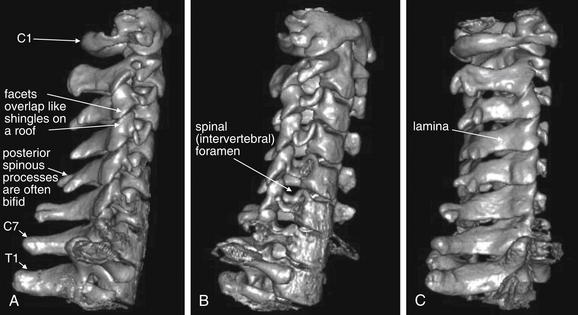
Figure 3-1 Lateral and oblique three-dimensional views of the normal cervical spine.
This three-dimensional reconstruction of the cervical spine was generated from standard computed tomography axial images using 1.25-mm slice thickness. Images like this are not routinely reviewed by emergency physicians, but they provide a good starting point for our discussion of cervical spine imaging. A, A lateral view, showing the normal relationship of C1 through T1 vertebrae. Compare this with the lateral x-ray in Figures 3-8 and 3-9. Note the overlap of the cervical facet joints, like shingles on a roof. B, An anterior oblique view, similar in perspective to an oblique x-ray view sometimes obtained to inspect for narrowing of the spinal foramen through which spinal nerves exit. C, A posterior oblique view. This has no routine x-ray equivalent but demonstrates the spinal lamina and posterior processes.
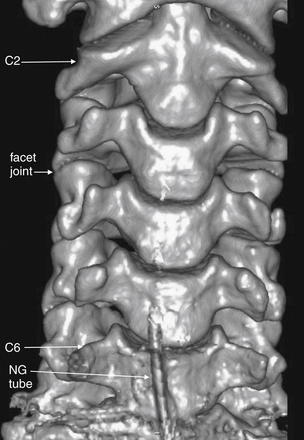
Figure 3-2 Anterior three-dimensional view of the normal cervical spine.
This three-dimensional reconstruction from axial cervical spine images shares the same perspective with an anterior–posterior x-ray or coronal computed tomography (CT) views. The C1 vertebrae is cropped from this image—we look at C1 in detail in Figure 3-3. C7 and T1 are also not in this image—as we discuss later, these must be seen in an x-ray series to allow adequate evaluation of the cervical spine. Note how the facet joints are not horizontal but slope caudad from anterior to posterior. As a result, these joints are not fully seen in a single axial CT image, as you will see in future figures. Also note how the spacing of vertebral bodies is symmetrical.
The lower portion of this reconstruction shows artifacts from a nasogastric (NG) tube.
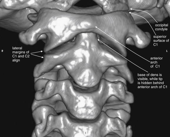
Figure 3-3 C1 and C2 view of the normal cervical spine.
This three-dimensional reconstruction from computed tomography (CT) axial images focuses on the occipital–cervical junction and the C1-2 (atlantoaxial) junction. Note how the occipital condyles articulate with the superior surface of C1. The tip of the dens is hidden from view behind the anterior arch of C1. Two-dimensional slices can be more useful in identifying injuries because superficial structures do not obscure the view of deeper structures. The lateral margins of C1 and C2 align. These features will prove important in our discussions of fractures of this region in later figures.
The author generated this figure from a standard cervical CT scan using open-source software called OsiriX.
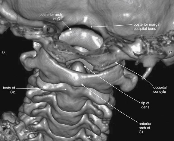
Figure 3-4 C1 and C2 view of the normal cervical spine.
Again, this three-dimensional reconstruction from computed tomography (CT) axial images focuses on the occipital–cervical junction and the C1-2 (atlantoaxial) junction. Compared with Figure 3-3, the view has been shifted to look down slightly upon C1. The tip of the dens is visible behind the anterior arch of C1. The occipital condyles articulate with the superior surface of C1. The skull has been cut away in this model, allowing the posterior ring of C1 to be seen through the foramen magnum. Later in this chapter we examine injuries to this region using multiplanar cross-sectional CT images. Refer to this figure for orientation if the two-dimensional images appear confusing.
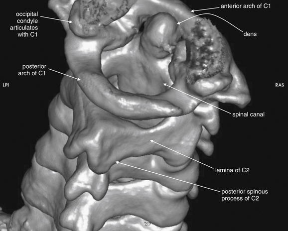
Figure 3-5 C1 and C2 view of the normal cervical spine.
The skull base has been cut away nearly completely in this CT model, allowing the ring of C1 and its relationship to the dens of C2 to be seen in detail. Portions of the occipital condyles are still seen articulating with the superior surface of C1. Note that C1 does not have a true vertebral body—instead, the dens occupies the space immediately posterior to the anterior arch of C1. The posterior arch of C1 is in full view, and this perspective gives good views of the spinal canal, lamina of C2, and posterior spinous processes of C2 and more caudad vertebral bodies. C1 does not have a posterior spinous process.
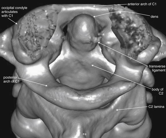
Figure 3-6 C1 and C2 view of the normal cervical spine.
As in Figure 3-5, this three dimensional CT model has been rotated and the skull base cut away to allow the ring of C1 and its relationship to the dens of C2 to be seen in detail. The posterior arch of C1 is in full view. The transverse ligament, which holds the dens in position against the anterior arch of C1, is partially calcified in this patient and is therefore visible.
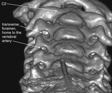
Figure 3-7 Transverse foramen (foramen transversarium).
This three-dimensional CT model is oriented with the observer looking cephalad along the anterior surface of the cervical spine. A series of holes perforating the transverse processes of each vertebra can be seen—the transverse foramen. These canals house the vertebral arteries as they ascend to the brain. Fractures through the transverse processes can result in arterial injuries, as can rotational injuries such as unilateral facet dislocation and subluxation injuries such as bilateral jumped facets. These injuries are discussed in detail in later figures, illustrated with the two-dimensional multiplanar computed tomography images routinely available to emergency physicians. Use this figure to understand how fractures and malalignment of vertebral bodies can disrupt the normal canal containing the vertebral arteries.
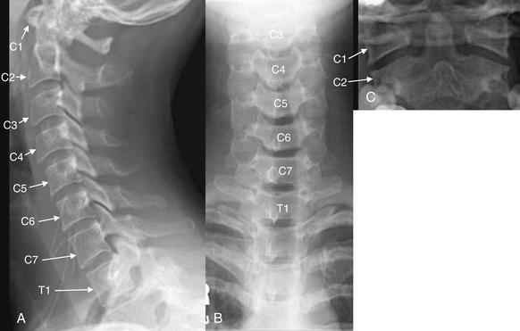
Figure 3-8 Lateral, anterior – posterior (AP) and odontoid view x-rays of the normal cervical spine.
A plain x-ray cervical spine series consists of three standard views: lateral (A), AP (B), and odontoid (C). An adequate series requires visualization of the entire cervical spine and its cephalad and caudad borders: the skull base and the first thoracic vertebral body (T1). An adequate odontoid x-ray must include the entire dens and the lateral borders of C1 and C2. We examine each of these views in more detail in the next several figures.
Normal Features of the Lateral X-ray
The lateral x-ray (Figures 3-8 through 3-13; see also 3-19 and 3-20) provides information about gross fractures, as well as alignment of vertebral bodies relative to one another. In addition, prevertebral soft tissue widening may suggest soft-tissue hematoma or swelling, a surrogate marker of fractures that may themselves be invisible on plain film. The x-ray must visualize the cervical spine from the skull base to the C7-T1 (cervical seventh vertebra–thoracic first vertebra) junction. This is not an arbitrary definition of an adequate plain film. An x-ray that fails to visualize the entire cervical spine and its junctions with the adjacent skull and thoracic spine may miss injuries. Widening of the space between the C1 vertebra and the skull base may be a subtle indication of a devastating occipital–cervical dissociation—although this injury is usually clinically evident with a moribund patient with quadriplegia. At the caudad end of the cervical spine, it is essential to visualize the C7-T1 junction to avoid missing subluxation of these vertebral bodies relative to one another. This injury is made more likely by the sudden change in the mobility of the spine, from the highly mobile cervical spine to the relative immobile thoracic spine, which is supported by the buttresses of the ribs.
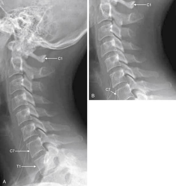
Figure 3-9 Adequate and inadequate lateral cervical spine x-rays.
A, An adequate lateral cervical spine x-ray, showing the entire cervical spine and its cephalad border (the skull base) and caudad border (T1). B, The image is inadequate because C1 and T1 are not seen fully. Fractures or subluxation at these locations would be missed. The x-ray should be repeated, perhaps using special views such as the swimmer’s view to visualize the C7-T1 junction, or computed tomography could be used.
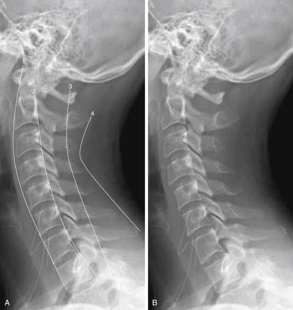
Figure 3-10 Interpretation of the lateral cervical spine x-ray.
A normal lateral cervical spine x-ray, with (A) and without (B) labels.
The spine should be inspected for four curved, roughly parallel lines:
The spinal canal, which houses the spinal cord, lies between lines 2 and 3.
If all lines are intact, the vertebral bodies should be properly aligned and the spinal canal should be preserved.
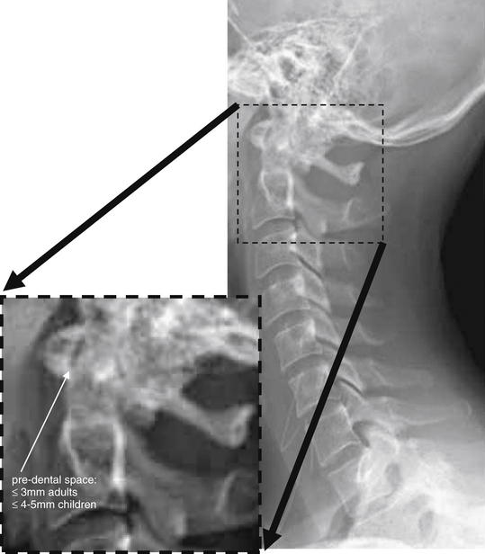
Figure 3-11 Evaluation of predental space.
On lateral cervical spine x-ray, the predental space should be evaluated. Several injury patterns can widen this space. Fracture of the ring of C1 can allow the anterior portion of the ring to migrate anteriorly with respect to the dens. Dens fracture can allow posterior migration of the dens relative to the ring of C1. Subluxation of the transverse ligament can allow widening of this space. Patients with rheumatoid arthritis are at particular risk of this latter abnormality.
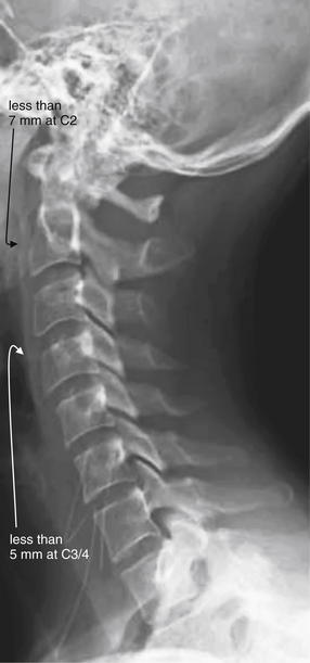
Figure 3-12 Prevertebral soft tissues.
The lateral cervical spine x-ray should be examined for the width of prevertebral soft tissues. Widening suggests cervical spine injury with prevertebral soft-tissue swelling or hematoma, even in the absence of visible fracture. Lack of widening is relatively reassuring, as a fracture or ligamentous injury would be expected to be accompanied by some degree of soft-tissue swelling or hemorrhage.
In adults, soft tissues should be less than 7 mm in width at C2 and less than 5 mm at C3 and C4.
A rule of thumb in children is that the prevertebral soft tissues should be less than half the width of the adjacent vertebral body. False widening may be seen on expiratory films in children younger than 2 years, particularly if images are obtained during crying, which creates forced expiration.
A normal lateral cervical spine image shows a gentle cervical lordosis—a curve with its convex border oriented anteriorly (see Figure 3-10). This lordosis may be straightened slightly due to the presence of the cervical collar. When all cervical vertebrae are intact and in normal alignment with one another, this cervical lordosis results in four parallel curved lines, for which the lateral x-ray should be inspected (the numbered lines in Figure 3-10):
In addition, the lateral film should be examined with attention to the following:
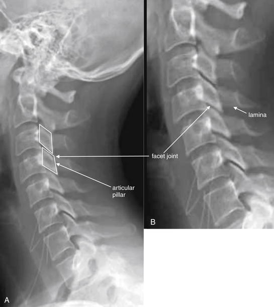
Figure 3-13 Assessment of facet joints.
A, Lateral cervical spine x-ray. B, Close-up. The facets should overlap like shingles on a roof. In the case of jumped or perched facet joints, the degree of facet overlap at the level of injury will be less than the overlap at uninjured levels. The facets can be recognized by their rhomboid shape in profile. Fracture through the facets and lamina is also common and should be looked for carefully.
Normal Features of the Anterior-posterior X-ray
The AP x-ray (Figure 3-14) provides information about lateral alignment of vertebral bodies with one another. A small number of additional fractures (particularly oblique fractures) may be noted on the AP x-ray, and subtle abnormalities from the lateral film may be confirmed. The posterior spinous processes should be centered in the midline and aligned with one another. The cortex of each vertebral body should be intact. The height of and spacing between adjacent vertebral bodies should be uniform.
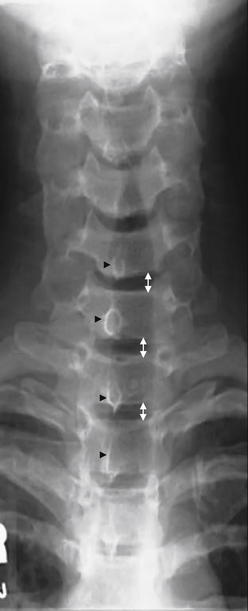
Figure 3-14 Anterior–posterior (AP) normal cervical spine x-ray.
The AP cervical spine x-ray should be inspected for gross fractures. The intervertebral spacing (double arrows) should be symmetrical if the intervertebral discs (not visible on x-ray) are intact. The posterior spinous processes (black arrowheads) should project directly backward out of the plane of the x-ray and should be aligned with one another. In cases of unilateral jumped facet joint, rotation of one vertebral body relative to the adjacent bodies causes the posterior spinous process to project at an angle and thus not be aligned with the processes of other vertebrae.
Open-Mouth Odontoid X-ray
The open-mouth odontoid view (Figures 3-15 and 3-16) is essential for evaluation of two important injury patterns:
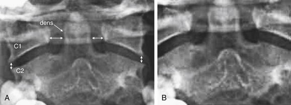
Figure 3-15 Adequate and inadequate open-mouth odontoid view x-ray.
An adequate open-mouth odontoid view must visualize the entire dens and the lateral borders of C1 and C2. An incompletely visualized dens could result in an undiagnosed dens fracture. The lateral borders of C1 and C2 must be seen to assess for misalignment, which can occur in the setting of C1 burst fracture, in which the lateral masses of C1 are displaced laterally.
A, An adequate view. The lateral borders of C1 and C2 are visible and align normally. The spaces between the dens and the lateral masses of C1 are symmetrical. The entire dens is visible and appears intact. B, An inadequate view with the tip of the dens and the lateral masses of C1 and C2 cropped. Alignment and fracture cannot be assessed.
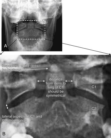
Figure 3-16 Normal open-mouth odontoid view x-ray.
The open-mouth odontoid view is essential for evaluation of potential dens fractures and fractures of the C1 ring.
A, Routine open-mouth odontoid image. B, Close-up of the region of interest, which includes C2 with the dens, as well as the lateral masses of C1.
The open-mouth odontoid view is so called because it is obtained with the patient’s mouth opened as wide as possible, with the x-ray tube aimed into the open mouth. This gives a direct view of C1 and C2. Issues that may prevent adequate visualization include an obtunded or uncooperative patient who is unable to comply with this maneuver; a patient with trismus, temporomandibular joint disease, or other injuries (e.g., mandibular fractures) that prevent full opening of the mouth; and the presence of significant metal dental work. Sometimes, the cervical spine collar may restrict mouth opening too much to allow an adequate open-mouth odontoid view. When an adequate open-mouth odontoid view cannot be obtained, CT should be performed to avoid a missed injury of C1 or C2.
An adequate open-mouth odontoid view visualizes the entire dens and the lateral margins of both C1 and C2. A fully visualized dens is essential for evaluation of dens fractures. The cortex of the dens should be carefully inspected for defects. Shadows of overlying structures such as central incisors can simulate or hide fractures, so a wide-open view with no overlap of teeth with the dens is desirable. When the ring of C1 is intact, the lateral margins of C1 should align with the lateral margins of C2. When fractured, C1 typically “bursts,” with the fracture fragments spreading outward. Consequently, an indirect sign of C1 fracture is misalignment of the lateral margins of C1 with the lateral margins of C2. Frequently, the lateral margins of C1 appear displaced laterally compared with the lateral margins of C2, although medial displacement of C1 is also possible. This finding may be unilateral or bilateral. When C1 is intact and the patient is facing directly forward, the distance between the dens and the medial borders of the C1 ring should be bilaterally symmetrical. When C1 is fractured, displacement of fracture fragments typically renders this distance asymmetrical. The lateral margins of C1 and C2 may be hidden by radiopaque dental fillings, especially if the patient’s mouth is not fully opened.
The standard three-view series just described is sometimes augmented with additional plain x-ray views. Adding two oblique views allows visualization of the pedicles, lamina, and neural foramina. Although this technique may be useful in selected cases, this “five-view” technique has been compared with the standard three views and does not detect additional injuries at a rate high enough to make five views a useful standard. The five-view series was insensitive (44%) compared with CT in a high-risk group of patients with altered mental status and a high rate of cervical spine injury (>10%).6 CT should be obtained if subtle lamina, pedicle, or neural foramen injuries are suspected.
In cases in which the C7-T1 junction is not visualized on the lateral x-ray, “swimmer’s” (Figure 3-17) or “traction” views may allow visualization of this region. In a swimmer’s view, the patient is positioned with the arm closer to the x-ray detector raised above the head. This elevates the humeral head above the C7-T1 junction, preventing it from obscuring this area. The opposite arm is held at the patient’s side, resulting in that humeral head lying somewhat lower that the C7-T1 junction. Variations on this theme include having the patient raise both arms directly in front of the body or over the head. In a traction view, a health care worker pulls on the patient’s arms from a position at the foot of the bed, distracting the humeral heads down to reveal the C7-T1 junction – a method now discouraged because of the possibility of worsening spinal injury. When these maneuvers do not allow adequate visualization of C7-T1, CT is indicated. In many cases, these views are skipped in favor of CT. Flexion and extension views (Figure 3-18) are sometimes obtained to assess for ligamentous instability—the evidence for these views is discussed in detail later.
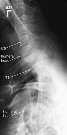
Figure 3-17 Swimmer’s view x-ray of the cervical spine.
A swimmer’s view is a lateral cervical spine x-ray in which the patient is positioned with one arm raised above the head. This position tilts the shoulder girdle, elevating one humeral head and depressing the other, thus revealing the C7-T1 junction. Other variations on the swimmer’s position are sometimes used, including raising both arms above the head. The swimmer’s view is only necessary when the C7-T1 junction is not visualized on a standard lateral x-ray. Today, computed tomography is more commonly used to visualize this region.
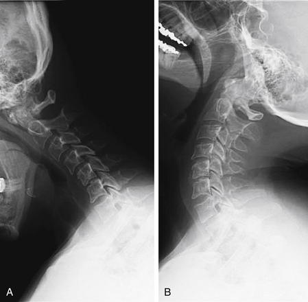
Figure 3-18 Flexion and extension x-rays of the cervical spine.
Flexion (A) and extension (B) views may be performed to evaluate for ligamentous injury if plain films in neutral position do not show fractures or subluxation but the patient has persistent pain. The patient is asked to flex and extend the cervical spine actively, stopping if pain or neurologic symptoms develop. Subluxation suggests a ligamentous injury. Passive flexion and extension (in which the patient is manipulated by the examiner) should never be used, because this may cause cervical spinal cord injury. The utility of flexion–extension views is an area of controversy, but generally these are not useful in the evaluation of acute trauma because patients with acute pain are often unable to flex or extend sufficiently to exclude ligamentous injury.
Computed Tomography of the Cervical Spine
CT scan evaluates for fractures and dislocations with high sensitivity and specificity. Soft-tissue injuries are demonstrated less directly and accurately (Box 3-1). CT scan should be performed in several situations (Box 3-2):
Interpreting Cervical Computed Tomography
Interpretation of cervical CT can be based on many of the same criteria used for plain x-ray. We make some direct comparisons of imaging findings on CT and x-ray, so skills you may already have from x-ray can be translated to CT. For those with little experience with either modality, starting with CT may prove easier, with CT findings then clarifying subtle findings on x-ray. We take a step-by-step approach, using the sagittal, coronal, and axial images for different purposes. Each image series should be reviewed, because fractures in the plane of a given image series are difficult to see in that series but are readily apparent in perpendicular planes. We spend relatively little time up front on normal findings; instead, we concentrate on pointing out abnormalities in the figures that follow, with comparison to normal findings.
CT has high resolution for bony injury and directly detects fractures and dislocations. Modern CT scanners allow multiplanar and three-dimensional reconstructions, facilitating injury characterization. Image data is helically acquired as the patient passes through the CT gantry, typically at 1-mm or submillimeter slice thickness. Reconstructions are performed in sagittal, coronal, and axial planes (Table 3-2). The sagittal plane yields information similar to that from the lateral plain x-ray. The coronal plane yields information similar to that from the AP and odontoid plain x-ray views. Axial views give detailed anatomy of individual vertebral bodies, including clear views of the lamina, pedicles, transverse foramen enclosing the vertebral arteries, and spinal canal. Although the spinal cord is not well visualized on CT, the preceding image sets allow the canal to be carefully inspected for fracture fragments or dislocations that might impinge on the spinal cord. CT is considered to have outstanding sensitivity for fractures and dislocations—a normal CT viewed on bone windows effectively rules out these injuries. Nevertheless, it remains common practice to continue spine immobilization following a normal CT if the patient cannot be clinically evaluated for neurologic complaints or continued pain, though recent studies suggest a low risk of unstable cervical injuries following normal CT (see later discussion).
Step 1: Examine the Sagittal Computed Tomography Reconstructions
The sagittal CT reconstructions provide detailed information about the AP alignment of the cervical spine, as well as fractures or subluxations that may impinge on the spinal canal. Start your evaluation by selecting bone windows, and then move to a slice in the middle of the sagittal series, corresponding to the midsagittal plane (Figure 3-19). If you are experienced in interpreting cervical spine x-rays, this image should look familiar—it strongly resembles the lateral cervical spine x-ray, without the confusing overlay of bones and soft tissues from other planes. Just as with the lateral x-ray view, the midsagittal CT image allows assessment of alignment, using the curves of the anterior and posterior longitudinal ligaments and the spinolaminar line. In this view, the spinal canal can be seen in detail and inspected for any fracture fragments or subluxation of vertebral bodies that could impinge on the spinal cord. Remember that you are only looking at a single plane—you need to scroll laterally to the patient’s right and then left to perform these same steps in planes moving away from the patient’s midline. In the midsagittal plane, notice how large the dens is—perhaps you did not appreciate this on x-ray, but look now at the lateral x-ray for comparison. Check the contour of the dens for fracture lines, and if fracture is present, inspect for retropulsion of the dens into the spinal canal. Inspect the predental space for widening. Look at prevertebral soft tissues for increased thickness suggesting soft-tissue injury. Inspect each vertebral body for fracture lines. Check the spinal lamina and posterior spinous processes for fracture. Notice that in the midsagittal plane, the facet joints are not visible. These are lateral structures and are seen in the far lateral parasagittal images (Figure 3-20). Inspect these joints for unilateral or bilateral dislocation (jumped facets, shown in a later figure). At the cephalad limit of the cervical spine, inspect the articulation of the occipital condyles with C1 (see Figure 3-20). It may take you some time to become accustomed to imagining the cervical spine in three dimensions as you scroll through it in this plane.
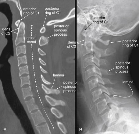
Figure 3-19 Normal mid-sagittal computed tomography (CT) image, compared with normal lateral cervical spine x-ray.
This 24-year-old female hydroplaned on a wet road at 45 mph and complained of midline cervical spine tenderness. Her CT is reviewed to demonstrate normal findings.
A, When reviewing CT sagittal images, follow the paradigm of the lateral x-ray. First, select bone windows. Next, select the midsagittal CT image and note the alignment of vertebral bodies, using the same four lines used for evaluating alignment on the lateral x-ray (see Figure 3-10). Then, inspect each vertebra for fractures (shown in subsequent figures). Notice how the facet joints are not visible in the midsagittal plane. Also notice how large the dens is and how small the ring of C1 is. Prevertebral soft tissues can be evaluated using the same criteria as for x-ray. B, Lateral x-ray for comparison.
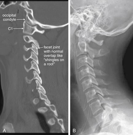
Figure 3-20 Normal parasagittal computed tomography (CT) image, compared with lateral cervical spine x-ray.
A, In this far lateral parasagittal CT image, the facet joints can be seen articulating normally, like shingles on a roof. The vertebral bodies are not seen in this plane, as we are far from the midline. The occipital condyles are seen articulating with C1. B, Lateral x-ray for comparison. Notice how much clearer the occipital–cervical junction is on CT.
Step 2: Inspect the Coronal Images
Use the coronal CT images (Figure 3-21) to simulate the open-mouth odontoid and AP cervical x-rays. Scroll through the “stack” of coronal images until you see the odontoid process projecting between the lateral masses of C1. Check for the same features you would expect on the open-mouth odontoid view. The lateral masses of C1 and C2 should align along their lateral borders. The spaces between the odontoid process and the lateral masses of C1 should be symmetrical. The odontoid process itself should have a smooth contour, with no fracture lines present. Once you have completed this evaluation, scroll in anterior and posterior directions through the stack of images, inspecting for fractures of the vertebral bodies, facets, and transverse processes. Fractures in the sagittal plane are visible on coronal images, and may be missed on the sagittal images reviewed first. Look for lateral displacement of vertebral bodies with respect to one another. Spend some time reviewing the figures in this chapter to familiarize yourself with the most common fracture patterns.
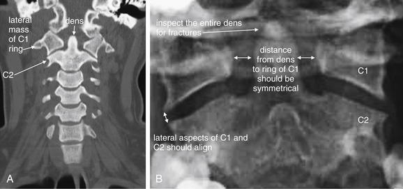
Figure 3-21 Normal coronal computed tomography image, compared with odontoid view x-ray.
A, Same patient as Figures 3-19 and 3-20. A coronal image centered on the odontoid (dens) and C1, simulating the open-mouth odontoid x-ray. CT findings of a normal dens are the same as those seen on open-mouth odontoid x-ray, and deviation from normal should heighten suspicion for injury, even when a fracture line is not seen. Subluxation without fracture may be present. The lateral borders of the C1 and C2 vertebral bodies should align. Fractures of the ring of C1 (Jefferson fractures) commonly result in radial spread of C1 fragments, disturbing this normal alignment. The spaces between the lateral masses of C1 and the odontoid process should be bilaterally symmetrical. C1 fractures can result in asymmetrical spread of fragments, and subluxation of the transverse ligament can also result in asymmetry. The odontoid process should be smoothly contoured with no visible fracture lines. A slight notched appearance on each side of the base of the dens is normal. B, Open-mouth odontoid x-ray for comparison.
Step 3: Inspect the Axial Computed Tomography Images
The axial CT images (Figure 3-22) have no immediate analogue in the normal three-view x-ray series. They can provide additional information not readily seen on the sagittal and coronal views. Particularly, they demonstrate fractures of the canals housing the vertebral arteries (foramen transversarium), which are more difficult to assess on other views. They also provide good views of fractures in the sagittal and coronal planes, which may not be seen well on those image series as they lie parallel to the plane of the image. From the sagittal images, you should already have a good idea of the alignment of the cervical spine, although the axial images can also demonstrate jumped facet joints. The axial images provide an en face view of the spinal canal. As you scroll from the level of C1 to T1, imagine yourself traveling down the spinal canal, and watch for fracture fragments that narrow the canal and may impinge on the spinal cord. Check the body, pedicles, lamina, and transverse and posterior spinous processes for fractures. We review many abnormal findings on the axial images in the figures throughout this chapter (see list, Table 3-1).
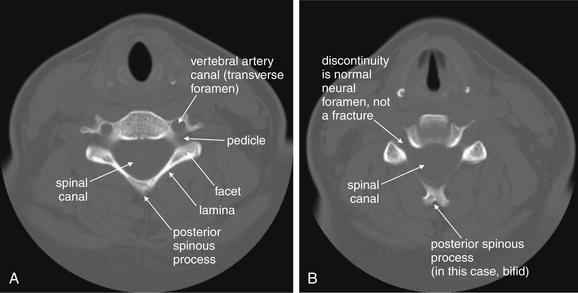
Figure 3-22 Normal axial computed tomography image.
Same patient as Figures 3-19 through 3-21. An axial image shows a cervical vertebra in cross section. The vertebral body, spinal canal, pedicles, lamina, and base of the posterior spinous process are visible. It takes some practice to become accustomed to the normal appearance of vertebrae in axial section. They are irregular structures and never lie completely within a single axial plane. Apparent discontinuities in the ring may be visible on some slices but may not represent fractures—instead, they simply reflect the irregular contour of the vertebrae passing in and out of the image plane. A, B, Two sequential slices.
Clinical Decision Rules: Who Needs Cervical Spine Imaging?
Indications for cervical spine imaging have been studied extensively, resulting in two well-validated clinical decision rules (CDRs) to aid the clinician in identifying patients who require cervical spine imaging. We review both rules in detail, discussing their strengths and weaknesses.
The National Emergency X-radiography Utilization Study
The National Emergency X-radiography Utilization Study (NEXUS) was a prospective study of 34,069 patients at 21 U.S. medical centers, examining blunt trauma patients undergoing cervical spine imaging (Box 3-3).4-5 This study was well planned and conducted and identified 818 patients with cervical spine injuries, comprising 2.4% of the study population. The study evaluated a CDR consisting of five clinical criteria, which had been suggested by prior studies (Box 3-4). Cervical spine imaging was considered necessary if any one of the five was present. The investigators prospectively defined a group of clinical unimportant cervical spine injuries which they did not expect their proposed rule to identify, as they would not be anticipated to lead to patient harm if undetected. This rule proved 99% sensitive, though only 12.9% specific for clinically important acute cervical spine fracture. The negative predictive value of the rule was 99.8%, with a positive predictive value of only 2.7%. Application of the rule would have reduced cervical spine imaging by 12.6%. The rule failed to identify 8 of 818 injuries—2 which would have been clinically significant, 1 of which was treated surgically. Application of this rule is estimated to miss one injury in 125 years of clinical practice by a typical emergency physician.
The Canadian Cervical Spine Rule
The Canadian Cervical Spine Rule (CCR) (Figure 3-23) is a classic example of a methodologically rigorous CDR. CDRs are aids to bedside decision making, intended to reduce the cost, time, and adverse consequences of care, such as radiation exposures from diagnostic imaging. CDRs must be rapid to apply, inexpensive, and sensitive to avoid missing important pathology. They must be specific enough to reduce subsequent test utilization; otherwise, they fail their primary objective. Typically, CDRs use readily available information from the history and physical examination, occasionally supplemented by simple, rapid, and inexpensive bedside tests such as urinalysis.
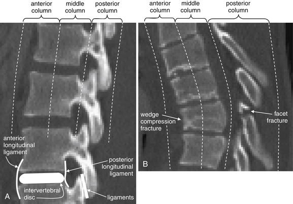
Figure 3-85 The three-column concept of thoracolumbar spine stability.
When evaluating the thoracolumbar spine for injury, consider the spine to be composed of three columns, as depicted here.
A, Sagittal CT image of lumbar spine. The anterior column is composed of the anterior half of the vertebral body and intervertebral disc, plus the anterior longitudinal ligament, which runs vertically along the anterior margin of each vertebral body. The middle column is composed of the posterior half of the vertebral body and intervertebral disc and the posterior longitudinal ligament, which runs vertically along the posterior margin of the vertebral bodies. The posterior column is composed of the facets with the strong ligaments joining these joints. When two of three columns are injured at a single spinal level, the spine is unstable. Injuries including subluxation, distraction, compression, and fracture may be sufficient to disrupt a column. B, Thoracic spine sagittal CT image, same patient. The anterior column has a compression injury, and the posterior column has a fracture. Only two of three columns need to be injured for the spine to be unstable.
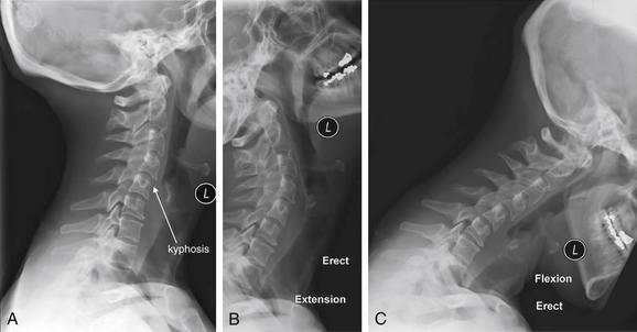
Figure 3-84 Acute cervical ligamentous injuries.
Same patient as in Figures 3-81 through 3-83. Flexion–extension x-rays obtained 2 weeks after the acute injury in the same patient. The lateral x-ray in a neutral position (A) continues to show the focal kyphosis seen on the computed tomography. However, in the extension (B) and flexion (C) views, no subluxation is seen. Prevertebral soft tissues remain somewhat wide, which may indicate resolving hematoma.
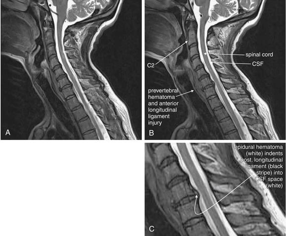
Figure 3-83 Acute cervical ligamentous injuries.
Same patient as in Figures 3-81 and 3-82. T2-weighted sagittal magnetic resonance imaging of the cervical spine demonstrate an area of prevertebral soft-tissue injury from the inferior margin of C4 to the superior margin of T1. This corresponds to an acute injury of the anterior longitudinal ligament with hematoma formation. In addition, the thecal sac is indented at the C4-5, C5-6, and C6-7 levels. This is a result of to epidural hematoma formation, visible as a bright signal on T2-weighted images. On this image sequence, fluid (cerebrospinal fluid, or CSF, and acute hemorrhage) appears white, while the spinal cord is dark gray.
Figure 3-82 Acute cervical ligamentous injuries.
Same patient as in Figure 3-81. A side-by-side comparison of results from sagittal computed tomography (CT) (A) and magnetic resonance imaging (MRI) (B) images. MRI gives excellent soft-tissue contrast, while CT provides high resolution for bone. On MRI, calcified bone gives only a signal void, because it has no free protons to resonate in the magnetic field and provide a radio signal. Differences between CT and MRI are described in Chapter 15.
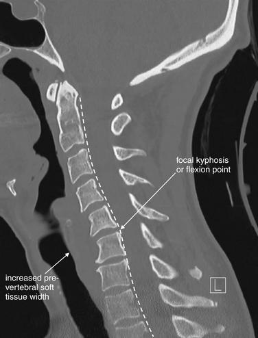
Figure 3-81 Acute cervical ligamentous injuries.
This patient experienced syncope and fell from a standing position, striking her occiput. She complained of exquisite neck pain, and computed tomography (CT) was performed. On this midsagittal CT image, the normal cervical lordosis is lost, likely because of the cervical collar. In addition, a subtle focal kyphosis is now present at the C5-6 level, associated with an increased prevertebral soft-tissue space at this level. Just as on plain x-ray, the posterior longitudinal ligament line should be a smooth, continuous curve, but in this case the curve is interrupted by a flexion point. Also, as with plain x-ray, increased prevertebral soft tissue width can be a sign of prevertebral hematoma associated with an acute injury. No fractures were identified on CT. Magnetic resonance imaging (MRI) was performed to further evaluate (Figures 3-82 and 3-83).
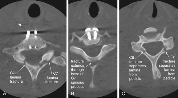
Figure 3-80 C6 and C7 lamina fractures.
Same patient as in Figures 3-78 and 3-79. Axial computed tomography images demonstrate lamina fractures through C7 (A, B) and C6 (C). The C6 fractures are present at the junction of the lamina and pedicle. The C7 fractures intersect the middle portion of the lamina and then enter the base of the spinous process at their more cephalad extent.
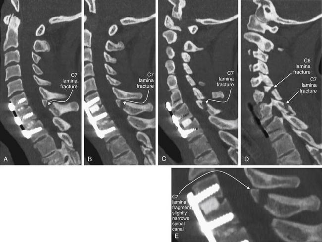
Figure 3-79 C6 and C7 laminar fractures.
Same patient as in Figure 3-78. These sagittal CT reconstructions—moving from just right of the midsagittal plane (A) toward the patient’s left (D)—demonstrate fractures through the C6 and C7 lamina. A fragment has drifted anteriorly into the spinal canal, slightly narrowing it at the C7 level. The patient has preexisting spinal fusion screws through C6, C7, and T1, which provide convenient landmarks. E, Close-up from B.
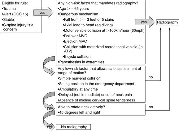
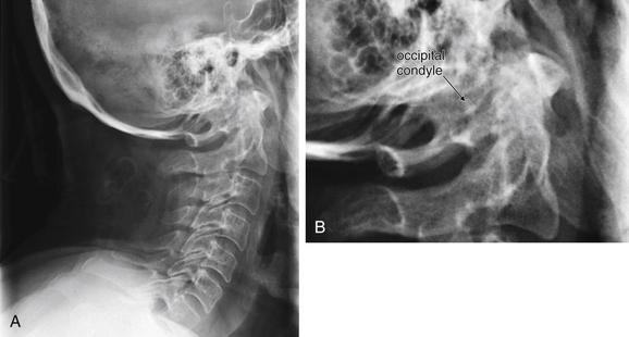
Figure 3-24 Cranial–cervical junction x-ray: Occipital condyle fracture.
A, Lateral cervical spine x-ray. B, Close-up of atlanto-occipital junction. Fractures of the occipital condyle are extremely difficult to see or invisible on plain x-ray, as this lateral cervical spine x-ray illustrates. Computed tomography (CT) scan of the region clearly demonstrated a fracture (see Figure 3-25), but the complex overlap of multiple structures at the junction of the skull base and C1 vertebral body masks the pathology on x-ray. The cervical spine alignment appears normal. This patient also has a C2 fracture known from CT but not seen on this view.
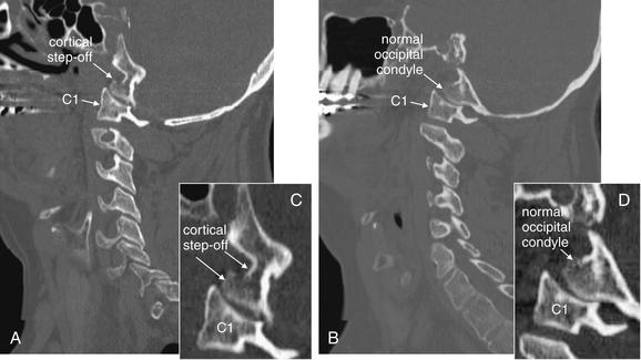
Figure 3-25 Cranial–cervical junction CT: Occipital condyle fracture.
A, On this sagittal CT reconstruction, a fracture through the occipital condyle is seen, with a cortical defect and step-off. B, The normal opposite side for comparison. Both images are far lateral to the midline. C, D, Close-ups from A and B, respectively.
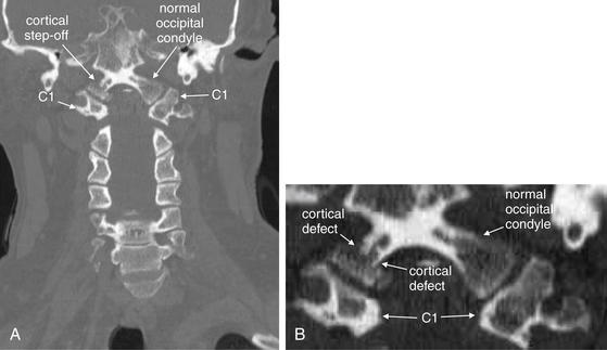
Figure 3-26 Cranial–cervical junction CT: Occipital condyle fracture.
A, On this coronal CT image, a fracture through the right occipital condyle is seen, with a cortical defect and step-off. Compare with the normal opposite side. B, Close-up showing this fracture in detail.
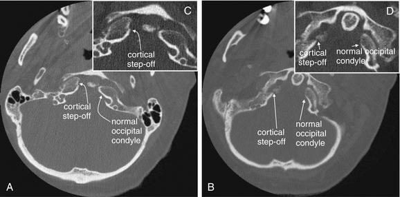
Figure 3-27 Cranial–cervical junction CT: Occipital condyle fracture.
A, B, On these axial views, a fracture through the right occipital condyle is seen, with a cortical defect and step-off. Compare with the normal left occipital condyle. C, D, Close-ups from A and B, respectively, show this fracture in detail. Although this step-off is subtle, it should not be confused with a reconstruction artifact. Note that other bony cortices in horizontal alignment with the fracture appear intact. If reconstruction artifact were at fault, cortices would appear disrupted in a horizontal line spanning the entire image.
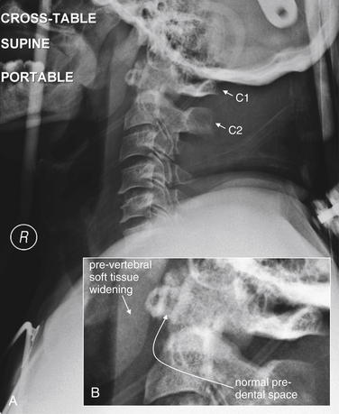
Figure 3-28 C1 Jefferson burst fracture.
A, Lateral cervical spine x-ray. B, Close-up.
C1 burst fractures (also called Jefferson fractures) result from axial force applied to the cervical spine, crushing the ring of C1 between the skull base and the body of C2. A common mechanism is diving into a pool and striking the head on the pool bottom. The resulting fragments of the C1 ring typically spread radially, and plain x-ray findings include a widened predental space (visible on a lateral x-ray), or laterally displaced margins of the C1 ring on an open-mouth odontoid x-ray. However, even a badly comminuted fracture can be difficult to detect on plain x-ray. Computed tomography (CT) is so widely used in the evaluation of potential cervical spine injuries that plain x-rays of this injury are becoming increasingly rare. In this patient, CT revealed a C1 fracture (Figures 3-29 through 3-31). This lateral x-ray with the patient in a halo device does not reveal the fracture directly, although the prevertebral soft tissues are slightly widened—the normal measurement being 7 mm or less. The predental space, which can be widened in burst fractures, is normal. This is not due to a failure of x-ray to detect an abnormality but rather due to the absence of predental widening in this patient, as shown on the patient’s CT (Figures 3-29 through 3-31).
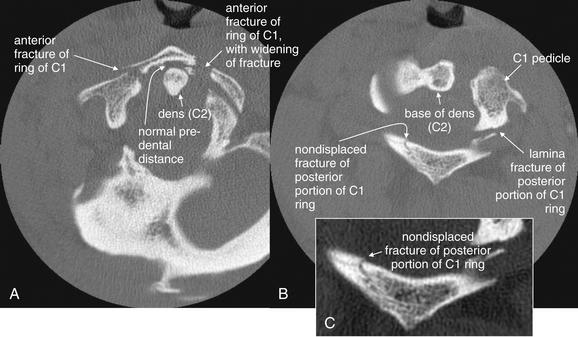
Figure 3-29 C1 Jefferson burst fracture: Cervical spine computed tomography (CT) without contrast, bone windows.
Same patient as in Figure 3-28. In these axial views, the ring of C1 is clearly fractured in multiple locations, with some radial spread of fracture fragments. Two slices are shown to capture both the anterior (A) and the posterior (B) portions of the ring of C1, as the position of the patient in the CT scanner prevents the entire ring from being seen in a single slice. C, Close-up from B. Discriminating fractures from the normal appearance of vertebral bodies as they pass in and out of the image plane takes practice. The task is easier when using a complete digital stack of images than when looking at selected images, as in a textbook like this.
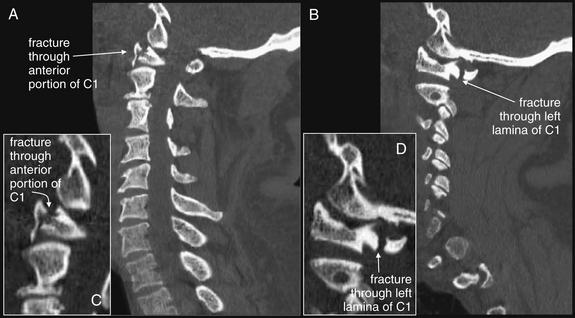
Figure 3-30 C1 Jefferson burst fracture, noncontrast CT, bone windows.
Same patient as in Figure 3-28. A, B, Sagittal computed tomography (CT) reconstructions, with close-ups from the same slices (C and D, respectively). The optimal CT plane for detecting a fracture depends on the predominant direction of the fracture plane. In this patient, the sagittal reformations look nearly normal, as many of the C1 fractures are in a sagittal plane parallel to the sagittal plane of reconstruction. One fracture line through the anterior portion of C1 runs in a coronal plane and is therefore visible on the sagittal views. The left lamina fracture seen on the axial reconstructions is also in a coronal plane, intersects the sagittal plane, and is thus visible on the sagittal views.
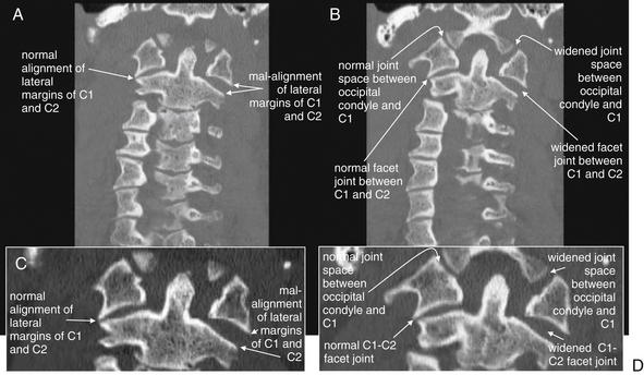
Figure 3-31 C1 Jefferson burst fracture, noncontrast CT, bone windows.
Same patient as in Figure 3-28. A burst fracture of C1 is often recognized on plain x-ray using the open-mouth odontoid view (see normal odontoid image, Figure 3-16). A, B, Coronal planar CT reformations (with close-ups in C and D, respectively) mimic the odontoid x-ray view. The fractures in this patient are not directly visible, as they lie predominantly in the coronal plane, parallel to the plane of reconstruction. However, the radial dispersion of the fracture fragments has caused a classic abnormality, malalignment of the lateral masses of C1 with the margins of the C2 vertebral body. As a result of the fractures, the left-hand portion of the C1 ring is freely mobile and has shifted laterally with respect to C2. In addition, the facet joint between C1 and C2 is widened, as is the joint space between the occipital condyle and C1.
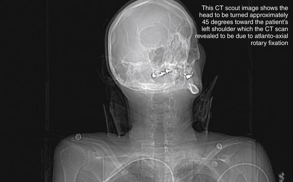
Figure 3-32 C1-2: Atlantoaxial rotary fixation.
Rotation of C1 on C2 is a normal joint motion—within limits. Excessive rotation at this level can result in facet dislocation (“jumped facet”), locking the joint in a malaligned position and preventing the head from assuming a midline position. This patient was in an altercation in which her assailant violently twisted her head. This computed tomography scout image shows the head to be turned approximately 45 degrees toward the patient’s left shoulder. Figures 3-33 and 3-34 evaluate this injury in more detail.
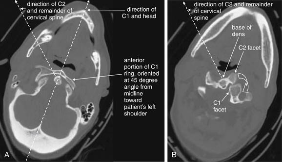
Figure 3-33 C1-2: Atlantoaxial rotary fixation.
Same patient as Figure 3-32, who has experienced a rotational injury to the spine. A, The skull and C1 moved as a unit, rotating toward the patient’s left shoulder relative to C2 and the remainder of the cervical spine. B, C2 and the remainder of the cervical spine are pointed toward the patient’s right shoulder. The facet joints of C1 and C2 are both visible, having rotated relative to one another. The C1 facet has subluxed completely posterior to the C2 facet. Normally, the two facets cannot be seen in the same axial image, as one is directly cephalad to the other.
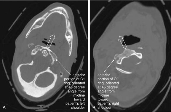
Figure 3-34 C1-2: Atlantoaxial rotary fixation.
Same patient as Figures 3-32 and 3-33, who has experienced a rotational injury to the spine. On these axial images, note how the head and C1 are facing the left shoulder (A), while C2 is directed toward the right shoulder (B).
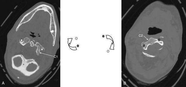
Figure 3-35 C1-2: Atlantoaxial rotary fixation.
Same patient as Figures 3-32 to 3-34, who has experienced a rotational injury to the spine. On these axial images, note how the rotation of C1 on C2 has changed the normal position of the canals housing the vertebral arteries (transverse foramen). Because of the patient’s rotated position, none of canals is seen completely on these images. Circular markers have been added to this figure to indicate the position of the vertebral arteries in the canals. In the center, they have been superimposed to show how rotation of this type could crimp or tear the vessels. This type of rotational injury can result in vertebral artery dissection or even transection. The patient underwent a computed tomography (CT) angiogram of the neck that showed no arterial injury. CT angiography for evaluation of cervical arterial injuries is discussed in Chapter 4.
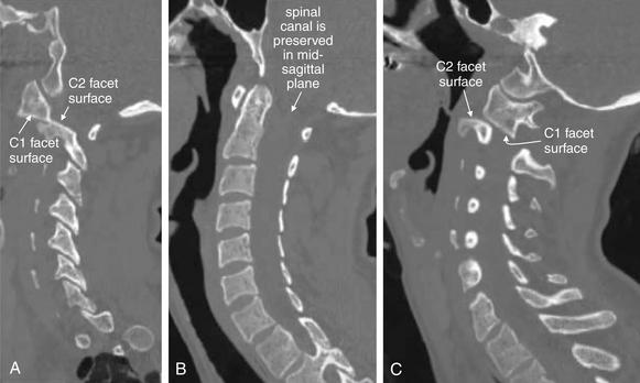
Figure 3-36 C1-2: Atlantoaxial rotary fixation.
Same patient as Figures 3-32 to 3-35, who has experienced a rotational injury to the spine. On these sagittal CT images, alignment looks surprisingly normal when viewing a nearly midsagittal image (B). However, sagittal images through far right lateral positions (A) and far left lateral positions (C) reveal that the C1-2 facet joints are completely subluxed. The mid-sagittal image looks normally aligned because the rotation occurred about a midsagittal pivot point. The central spinal canal is preserved in this rotational injury, and the patient had no neurologic deficits. This type of injury can severely injure the vertebral arteries, although fortunately, no injury occurred in this case.
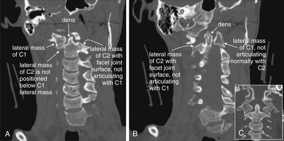
Figure 3-37 C1-2: Atlantoaxial rotary fixation.
Same patient as Figures 3-32 to 3-38, who has experienced a rotational injury to the spine. On these coronal CT images, the usual open-mouth odontoid appearance with a midline dens flanked by the lateral masses of C1 cannot be found, due to rotation of C1 on C2. A, Instead, the right lateral mass of C1 is visible, but not positioned normally above the C2 lateral mass. B, The left lateral mass of C1 is visible, but again the lateral mass of C2 is not in normal position below it. C, A normal coronal section for comparison.
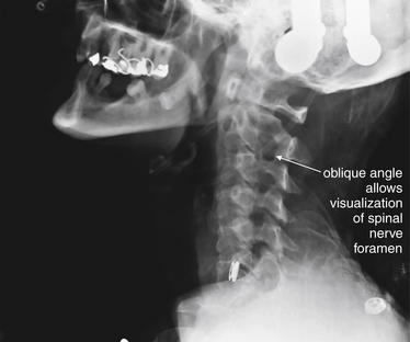
Figure 3-38 C1-2: Atlantoaxial rotary fixation.
Same patient as Figures 3-32 to 3-37, who has experienced a rotational injury to the spine. This lateral plain x-ray appears more like a standard oblique view due to the rotational injury. Oblique x-ray views are discussed in more detail in the text. In some institutions, they are part of the standard x-ray series.
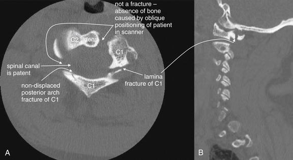
Figure 3-39 C1 posterior arch fracture, noncontrast CT, bone windows.
This patient sustained a Jefferson burst fracture of C1. Among the multiple fractures were posterior arch fractures, seen on these axial (A) and sagittal (B) views. These injuries can occur in isolation or with a comminuted burst pattern. As a result of the ring shape of C1, solitary fractures are rare, and two or more fractures are usually seen. Axial computed tomography images often cause confusion in novice readers, because the irregular three-dimensional shape of the vertebral bodies and asymmetrical positioning of the patient in the scanner often conspire to create the appearance of fracture when none exists. When an apparent defect in bone is found, always look through adjacent images in the digital stack to ensure that you are not seeing an artifact caused as the vertebral body passes out of the image plane. Although ring fractures of C1 can create fracture fragments that impinge upon the spinal cord, in this case, the spinal canal is patent.
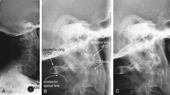
Figure 3-40 C2 dens fracture, type II.
A, Lateral cervical spine x-ray. B, Close-up from A. C, The same image without labels.
Fractures of the odontoid process or dens may be visible on the lateral cervical spine plain x-ray. Findings may include widening of the predental space or prevertebral soft tissues or actual cortical defects of the dens itself. The C1 ring may be intact but displaced posteriorly as well. The open-mouth odontoid plain x-ray view is also helpful for detecting this injury, although computed tomography is more sensitive and specific. In this patient, a cortical defect is present and the dens appears retropulsed. The anterior portion of the C1 ring is directly cephalad to the C2 body, instead of anterior to C2, which would be normal. The posterior ring of C1 is posteriorly displaced, so the posterior spinal line (also called posterior longitudinal ligament line) is disrupted. The dens itself is difficult to recognize. The prevertebral soft tissues are also widened, exceeding 7 mm at C2. Compare with the CT [in Figure 3-41].
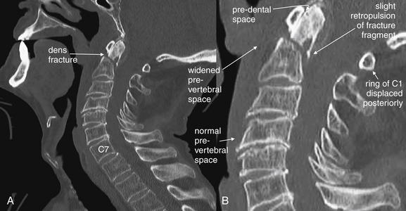
Figure 3-41 C2 dens fracture, type II.
Same patient as in Figure 3-40. A, In this midsagittal computed tomography image, a type II dens fracture is seen. The fractured dens is slightly retropulsed into the spinal canal, though no significant stenosis has resulted. The predental space is not wide. The prevertebral soft tissues anterior to C1 and C2 are somewhat widened, likely indicating hematoma. B, Close-up.
Look again at the lateral cervical spine x-ray in Figure 3-40 for comparison. As in that figure, the C1 ring here is attached to the dens by the transverse ligament and has moved posteriorly with the dens. This fracture is nearly parallel to the axial plane and is more difficult to identify on the standard axial images in Figure 3-42.
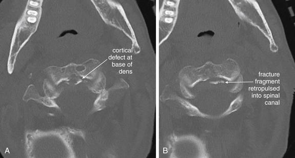
Figure 3-42 C2 dens fracture, type II, noncontrast CT, bone windows.
Same patient as in Figures 3-40 and 3-41, axial images (A, B). This type II dens fracture is nearly parallel to the axial plane and is therefore almost undetectable on the axial images. At the posterior aspect of the base of the dens, a fracture line extends horizontally, and small fracture fragments have been slightly retropulsed into the spinal canal. Look at the sagittal images in Figure 3-41 for comparison.
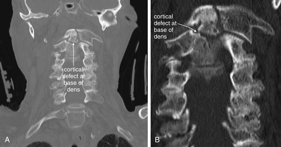
Figure 3-43 C2 dens fracture, type II. Same patient as in Figures 3-40 through 3-42.
A, In this coronal CT reconstruction, a transverse fracture line is seen extending across the base of the dens. An open-mouth odontoid x-ray would give a similar view of this fracture, though one was never obtained in this patient. B, Close-up.
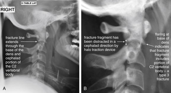
Figure 3-44 C2 dens fracture, type III.
A, Lateral cervical spine x-ray. B, Close-up. In a type III dens fracture, the fracture line extends into the body of the C2 vertebra. This patient was noted to have a type III dens fracture on CT scan. A lateral cervical spine x-ray was subsequently obtained after the patient was placed in a halo traction device. A fracture line through the dens and cephalad portion of the body of C2 is seen, with the dens fracture fragment distracted in a cephalad direction by the traction device. Figures 3-45 through 3-47 demonstrate this fracture in more detail in CT images.
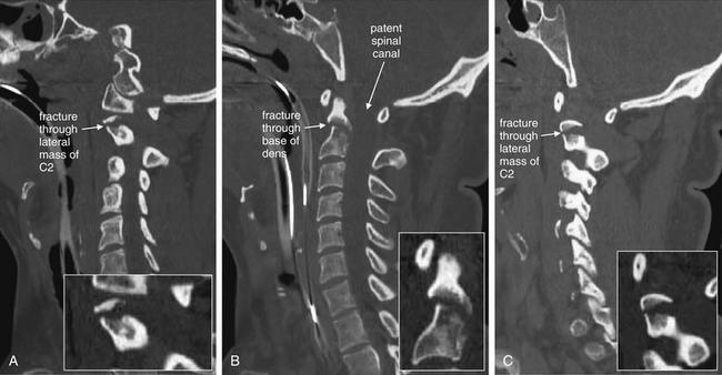
Figure 3-45 C2 dens fracture, type III.
Same patient as in Figure 3-44. Sagittal CT images with close-ups. These sagittal CT views delineate the fracture from Figure 3-44 in more detail. In a nearly midsagittal plane (B), this fracture resembles a type II dens fracture, with the fracture line running near the base of the dens. However, in more lateral parasagittal views (A, right parasagittal, and C, left parasagittal), the fracture line is seen running through the lateral masses of C2, consistent with a type III fracture. Importantly, there is no significant retropulsion of fracture fragments into the spinal canal.
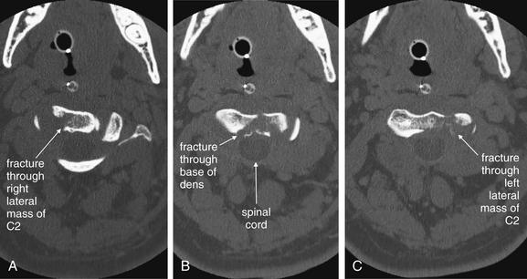
Figure 3-46 C2 dens fracture, type III.
Same patient as in Figures 3-44 and 3-45. These axial computed tomography (CT) views delineate the fracture in more detail. A, The fracture line extends from the central vertebral body of C2 toward the right lateral mass. B, The fracture shows a greater degree of comminution than is evident from the lateral x-ray (Figure 3-44). C, The fracture continues through the left lateral mass of C2. In all of these views, the spinal canal appears patent, and the spinal cord is faintly visible as a dark gray ellipse (because of its low density) on these bone window views.
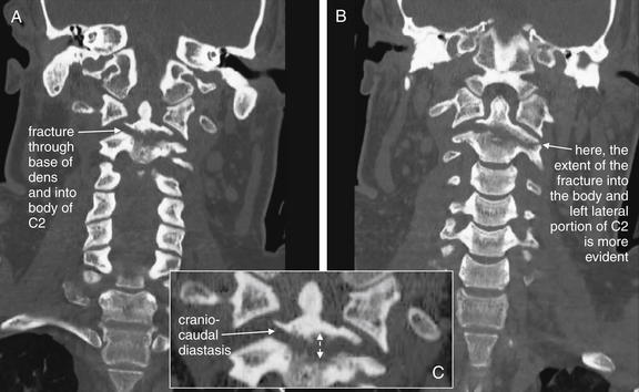
Figure 3-47 C2 dens fracture, type III.
Same patient as in Figure 3-44 to 3-46. A, B, These coronal computed tomography (CT) views delineate the fracture in more detail. The fracture extends across the body of C2, completely separating the dens. The fracture continues laterally into the left lateral mass of C2. C, The fracture fragment shows mild craniocaudal diastasis, with the fragment having moved cranially relative to the body of C2 (close-up from A). Compare this with the plain x-ray in Figure 3-44. The close-up helps to illustrate what might be seen on an open-mouth odontoid plain x-ray of this injury, had one been obtained.
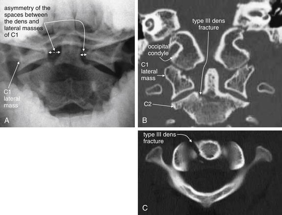
Figure 3-48 C2 dens fracture, type III, noncontrast CT.
A 17-year-old male with neck pain after falling off a bicycle. The patient had a normal neurologic examination with cervical spine tenderness to palpation.
A, The odontoid x-ray shows asymmetry of the spaces between the dens and lateral masses of C1. The space on the patient’s right is wider than the space on the patient’s left. Although no fracture is visible, this finding is concerning for dens fracture or for C1 burst fracture. Compare with the normal odontoid x-ray in Figure 3-16. B, A coronal computed tomography (CT) slice not only shows asymmetry but also confirms fracture—a type III dens fracture as it extends from the base of the dens to the body of C2. C, An axial CT image again confirms fracture. The patient was treated with halo fixation.
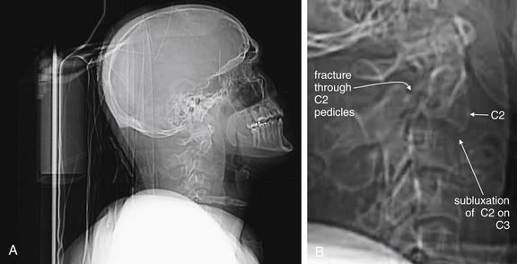
Figure 3-49 Hangman’s fracture of C2.
A, Lateral computed tomography (CT) scout image. B, Close-up. Scout images are usually used not for diagnosis but for selecting the region for the detailed CT scan. In this case, however, the scout images are diagnostic and give us an example of what might have been seen on lateral cervical spine x-ray, had one been obtained.
This patient has a hangman’s fracture of C2. The lateral scout image from the CT scan resembles a lateral cervical spine x-ray and shows typical findings, including subluxation of the body of C2 on C3. The body of C2 appears tipped slightly anteriorly. Fractures through the pedicles of C2 are faintly visible. The fracture is explored in detail in Figures 3-50 through 3-52.
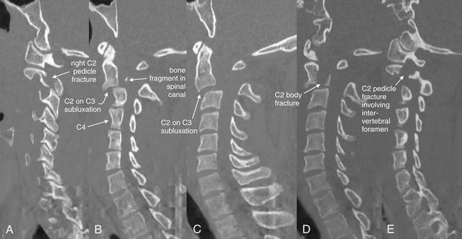
Figure 3-50 Hangman’s fracture of C2.
Same patient as in Figure 3-49. In this series of parasagittal CT images traversing from the patient’s right to left (A to E), a hangman’s fracture is demonstrated. A, The right pedicle is fractured. B, Just right of midline, the body of C2 is seen subluxed anteriorly on C3. C4 is labeled to assist in orientation. A tiny bone fragment is seen in the spinal canal. C, Subluxation of C2 on C3 of 6 mm is seen. D, The body of C2 is also fractured. E, The left pedicle is fractured, with the fracture involving the intervertebral foramen.
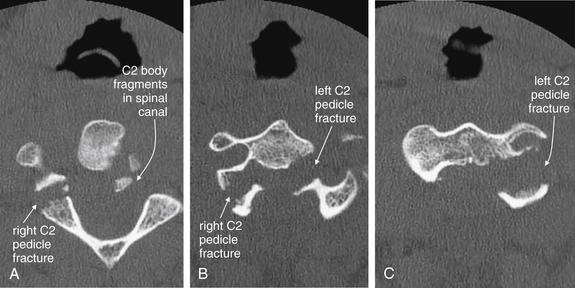
Figure 3-51 Hangman’s fracture of C2.
Same patient as in Figures 3-49 and 3-50. In this series of axial CT images (A to C), a hangman’s fracture of C2 is visible. This involves the left and right pedicles, as well as the body of C2. Fracture fragments have been retropulsed into the spinal canal. Although on plain x-ray this type of fracture often appears simple, computed tomography frequently reveals a badly comminuted fracture.
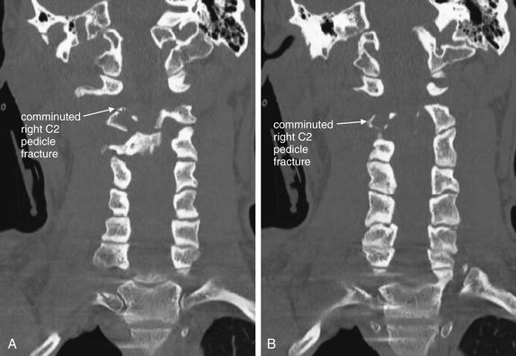
Figure 3-52 Hangman’s fracture of C2.
Same patient as in Figures 3-49 through 3-50. In these coronal CT images (A, B), the comminuted fracture through the right C2 pedicle is visible. The remaining fractures are difficult to see because they lie predominantly in a coronal plane, parallel to the plane of these computed tomography images. This emphasizes the importance of inspecting multiple image planes to detect fractures. Fractures are usually seen in images perpendicular to the fracture plane, while images in a parallel plane may disguise fractures. Fractures in an oblique plane may be visible in axial, sagittal, and coronal planes.
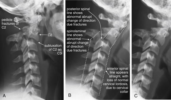
Figure 3-53 Hangman’s fracture of C2.
Two lateral x-ray views of another patient with a C2 hangman’s fracture (A, B; C same as B without labels). Compare these images with the scout computed tomography image and sagittal CT images in the prior case (Figures 3-49 and 3-50). Subluxation of C2 on C3 is visible. In addition, displaced fractures through the pedicles of C2 are visible. Look at the normal rhomboid appearance of the pedicles and lamina of the lower vertebrae, and the loss of that normal appearance at C2 as a consequence of fracture. The cervical spine appears quite straight with loss of the normal cervical lordosis due to the cervical collar on the patient. Notice that the anterior and posterior spinal lines (also called anterior and posterior longitudinal ligament lines) and spinolaminar line are all disrupted by the fracture. Make a habit of inspecting these lines, which can draw your attention to fractures.
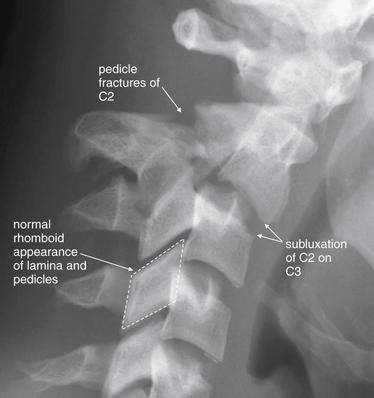
Figure 3-54 Hangman’s fracture of C2.
Close-up of the same C2 hangman’s fracture as Figure 3-53. Compare this image with the scout CT image and sagittal images in the prior case (Figures 3-49 and 3-50). Subluxation of C2 on C3 is visible. In addition, displaced fractures through the pedicles of C2 are visible. Look at the normal rhomboid appearance of the pedicles and lamina of the lower vertebrae—which is disrupted in C2 due to the fracture. The anterior and posterior spinal lines and spinolaminar line are all disrupted, as seen in Figure 3-53.
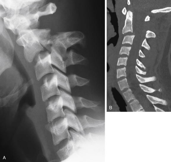
Figure 3-55 Hangman’s fracture of C2.
Take a moment to orient yourself to the lateral x-ray and a midsagittal CT slice in the same patient. In Figure 3-56, we focus on the region of C1 through C3, and explore the sagittal sections from the patient’s right to left, to understand this fracture in depth. A, The lateral x-ray compresses lots of information into a single plane—not all the fractures present are actually in the midline, which explains the relative lack of abnormalities on the midsagittal CT (B). Most of the fractures are through lateral structures of the C2 vertebra.
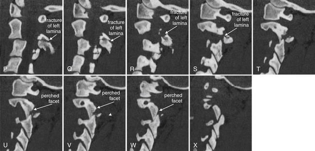
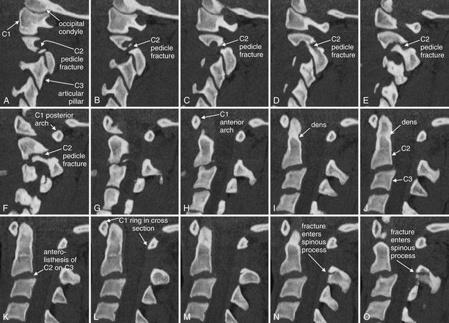
Figure 3-56 Hangman’s fracture of C2.
Sagittal computed tomography images from the same patient as in Figures 3-53 through 3-57 illustrate in more detail the abnormalities seen on the lateral plain x-ray. The sections shown are displayed from far right parasagittal (A), through the midline (K), and to far left sagittal (X). Take a moment to get oriented by looking at slice K, which shows the midline with the dens clearly demonstrated. In the far right slices starting at A, the facet joint is demonstrated. A fracture line runs through the right pedicle of C2, just anterior to the articular pillar. In the slices near the midline, the C2 body can be seen with anterior subluxation relative to C3, widening the spinal canal. In the slices approaching a left lateral position (O to U), a fracture is seen through the base of the spinous process and extending into the left lamina as you continue toward the patient’s left in the series. The result of the bilateral fractures is complete separation of the posterior elements of the vertebral body from the anterior elements, an unstable fracture. A perched facet (articular pillar) is seen in T to X; this injury is explored in more detail in a later figure, as it is not technically part of the hangman’s fracture pattern.
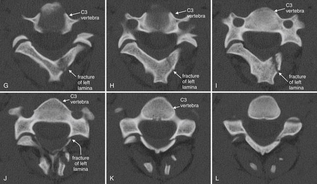
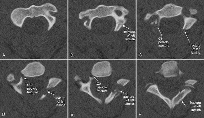
Figure 3-57 Hangman’s fracture of C2.
Same patient as in Figures 3-53 through 3-56. Axial views of the C2 vertebra again show a hangman’s fracture, with fractures of the right pedicle and left lamina, as illustrated in the sagittal slices in Figure 3-56. Follow the series cephalad to caudad from A (just below the junction of the dens with the body of C2) through the base of the C2 vertebral body (F). Because the vertebrae do not lie in a perfect axial plane, images G to L actually show more than one vertebra: the anterior structures are the vertebral body and appendages of C3, while the posterior structures are the posterior elements of C2. This may confuse novices, but is a feature common to axial imaging of the cervical spine. This patient also has a jumped left C2-3 facet joint, which is explored in more detail in a subsequent figure.
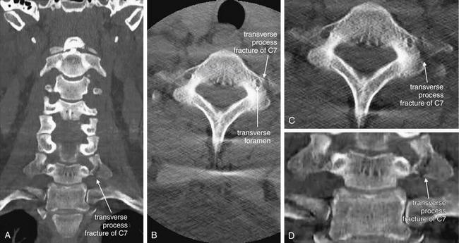
Figure 3-58 Transverse process fracture, noncontrast CT, bone windows.
Spinous process fractures are frequently noted on plain x-ray and computed tomography (CT), though they usually have little clinical significance. In these images, a transverse process fracture of C7 is seen. Because the fracture line is oriented in a nearly sagittal plane, it is invisible on the sagittal CT images (not shown). A, A coronal view shows the sagittal fracture. B, The fracture line narrowly misses the transverse foramen housing the vertebral artery. C, D, Close-ups from B and A, respectively.
The three-dimensional structure of the cervical spine is sometimes difficult to appreciate in the two dimensions of a single CT slice. A, The transverse processes of the more cephalad vertebral bodies are not well seen because of the normal cervical lordosis, which places the transverse processes of those vertebrae anterior to the coronal plane through the transverse processes of C7.
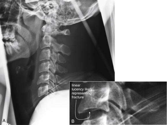
Figure 3-59 Cervical burst compression fracture, lateral cervical spine x-ray.
This patient has a C5 burst compression fracture, first noted on computed tomography (CT) scan. A, This lateral cervical spine x-ray was obtained after CT scan was performed and the patient had been placed in a halo traction device. The x-ray is technically inadequate, as it does not show C7 and T1. However, a subtle linear lucency through the inferior cortex of C5 may correspond to fractures seen on CT. The x-ray is otherwise quite normal, with normal alignment of the vertebral bodies. The prevertebral soft tissues are also normal. B, Close-up.
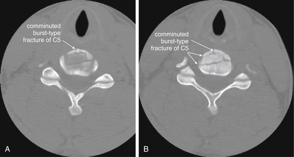
Figure 3-60 Cervical burst compression fracture, CT.
Same patient as in Figure 3-59. This patient has a C5 burst compression fracture. These fractures are inherently unstable, as they involve all three spinal columns (discussed in the text). Despite a highly comminuted fracture, no fracture fragments have become displaced into the spinal canal. A, B, Two adjacent axial slices.
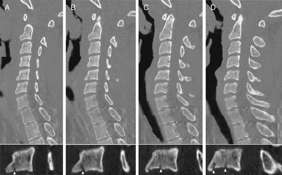
Figure 3-61 Cervical burst compression fracture.
Same patient as in Figures 3-59 and 3-60. In these parasagittal CT views (A to D), compression burst fractures of the C5 vertebral body are visible, although not as evident in the axial views in Figure 3-60. Fractures are visible where they violate the bony cortex and cross through the sagittal plane. Note that the spinal canal appears patent, with no retropulsed fracture fragments. The lower panels are close-ups of C5 from the corresponding upper panels, with fractures marked by arrowheads.
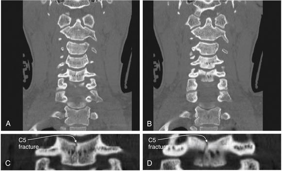
Figure 3-62 Cervical burst compression fracture.
Same patient as in Figures 3-59 through 3-61. On these coronal views (A, B), a C5 burst compression fracture is visible. A sagittally oriented fracture nearly bisects the vertebral body. C, D, Close-ups from A and B, respectively.
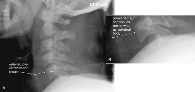
Figure 3-63 C6 flexion teardrop fracture.
A, This lateral cervical spine x-ray was obtained in a patient later found to have a C6 flexion teardrop fracture by computed tomography. B, Close-up.
Several important points are illustrated by this x-ray. First, an adequate lateral cervical spine x-ray must include C1 through T1. This x-ray visualized only through C5, with C6 being obscured by soft tissues of the shoulder. Ironically, this was the level of injury. Nonetheless, subtle signs of injury are present. The prevertebral soft tissues are prominent, a finding that can be due to prevertebral hemorrhage in the presence of a fracture. In addition, the distance between the C5 and the C6 (only partially visualized) spinous processes appears wide, indicating possible injury. The teardrop fragment was not noted but in retrospect may be visible. Compare with the CT in Figures 3-64 through 3-66.
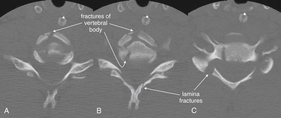
Figure 3-64 Flexion teardrop fracture.
Same patient as in Figure 3-63. These adjacent axial computed tomography (CT) images (A to C) demonstrate perhaps the most surprising feature of a flexion teardrop fracture—the degree of comminution. Lateral cervical spine x-rays and midsagittal CT reconstructions often suggest a simple fracture with a single anterior “teardrop”-shaped fragment. Instead, the axial views reveal a badly comminuted fracture of the C6 vertebral body, as well as fractures of the lamina.
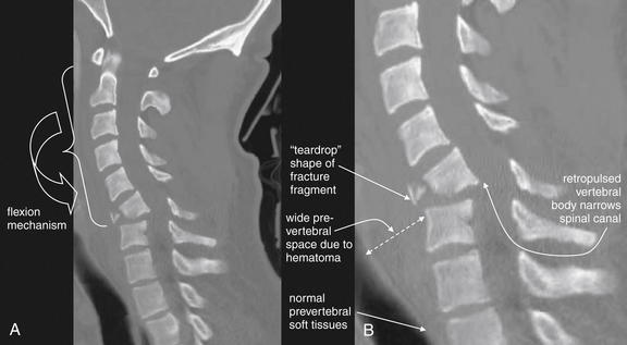
Figure 3-65 C6 flexion teardrop fracture.
Same patient as in Figures 3-63 and 3-64. A, A midsagittal computed tomography reconstruction demonstrates the classic “teardrop“-shaped fracture fragment, the flexion mechanism of injury, and the potential for narrowing of the spinal canal and spinal cord injury. B, Close-up.
The degree of comminution of the vertebral body is less evident here than on the axial views in Figure 3-64. The prevertebral soft-tissue swelling evident on the lateral x-ray (Figure 3-63) is seen well here.
This patient developed complete paraplegia as a result of this injury.
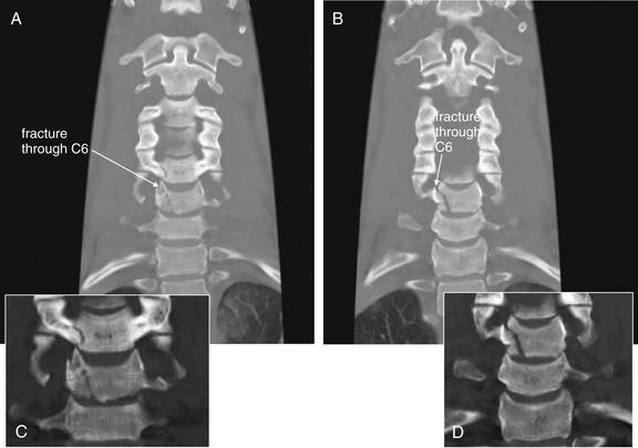
Figure 3-66 C6 flexion teardrop fracture.
Same patient as in Figures 3-63 through 3-65. These coronal computed tomography reconstructions (A, B, with close-ups in C and D, respectively) reveal an oblique, vertical fracture through the C6 vertebral body, as well as the C5 body.
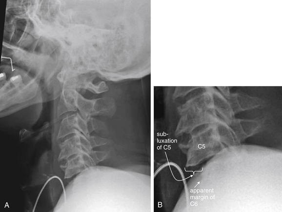
Figure 3-67 Bilateral facet dislocation (jumped facets).
This pattern of injury is most often seen between C3 and T1.
A, This lateral x-ray demonstrates the importance of visualizing the entire cervical spine from C1 to T1 in an adequate lateral x-ray. B, Close-up. In this case, the C6 vertebral body is partially obscured by soft tissues of the shoulder. C7 and T1 are not seen. Despite this, anterior subluxation of C5 on C6 is evident, with a ledge of C5 protruding by almost 50% of the width of the vertebral body. This degree of anterolisthesis is concerning for bilateral perched facets, which were confirmed on computed tomography scan (Figures 3-68 through 3-71).
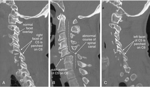
Figure 3-68 Bilateral facet dislocation (jumped facets).
Same patient as in Figure 3-67. This series of sagittal CT reconstructions spans from the patient’s right (A), through the midsagittal plane (B), and to the patient’s left (C). Bilateral perched facets are present. Compare the “perched” position with the normal appearance of facet joints, which demonstrate overlap like shingles on a roof. B, The anterior subluxation of C5 seen on the lateral x-ray (Figure 3-67) is readily evident. As a result, the spinal canal has a zigzag appearance, and the spinal cord is impinged upon (see MRI in Figures 3-70 and 3-71).
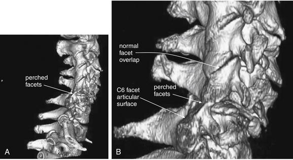
Figure 3-69 Bilateral facet dislocation (jumped facets): Three-dimensional reconstruction.
Same patient as in Figures 3-67 and 3-68. A, This three-dimensional reconstruction from the patient’s computed tomography scan depicts the facet dislocation. B, Close-up. Viewed from the patient’s right side, the C5-6 facet joint is seen to be perched. The C6 facet articular surface is completely exposed, as the entire cervical spine cephalad to this level has moved anteriorly. Notice how the facet joints above this level overlap normally like shingles on a roof.
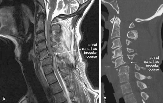
Figure 3-70 Bilateral facet dislocation (jumped facets).
Same patient as in Figures 3-67 through 3-69. A, A midsagittal T2-weighted magnetic resonance image shows narrowing of the spinal canal with cord impingement at the C5-6 level. B, The midsagittal computed tomography image for comparison. On T2-weighted images, fluid such as cerebrospinal fluid (CSF) appears white, while fat-containing soft tissues such as the spinal cord appear dark gray. Narrowing of the spinal canal has displaced the CSF that would normally surround the cord at the level of injury. Edema within the cord caused by spinal injury appears white on T2 images. The dura appears nearly black. An epidural spinal hematoma is visible, appearing white outside the dark dura. These findings are explored in detail in Figure 3-71.
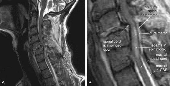
Figure 3-71 Bilateral facet dislocation (jumped facets).
Same patient as in Figures 3-67 through 3-70. A, A midsagittal T2-weighted magnetic resonance image shows narrowing of the spinal canal with cord impingement at the C5-6 level. B, Close-up.
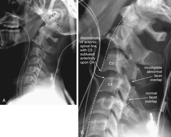
Figure 3-72 C3-4 unilateral facet dislocation.
A, This lateral cervical spine x-ray shows a unilateral facet dislocation. B, Close-up.
The normal curve of the anterior and posterior longitudinal spinal lines is disrupted, and C3 appears anteriorly subluxed relative to C4. Unlike the prior bilateral “perched” facet case, the pedicles and lamina show partial overlap, although the degree of overlap is not as great as usual.
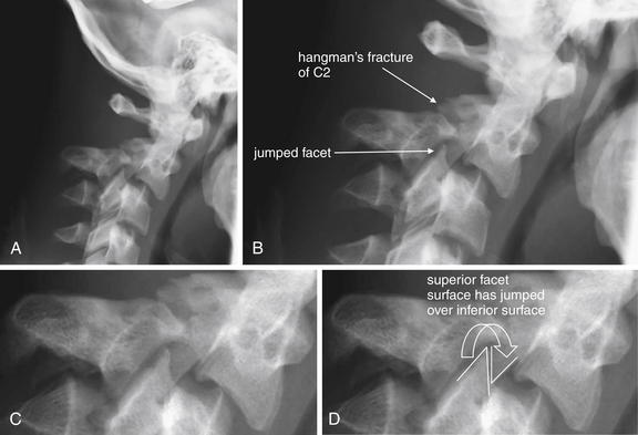
Figure 3-73 C2-3 unilateral facet dislocation (jumped facet).
In this patient, a hangman’s fracture of C2 and a unilateral facet joint dislocation are both present. The lateral x-ray shows predominantly the hangman’s fracture (A), although the anterior position of the jumped facet can be seen. B to D, Close-ups from A. Compare this appearance with the sagittal computed tomography images (Figure 3-75). Hangman’s fractures are explored in more detail in other figures.
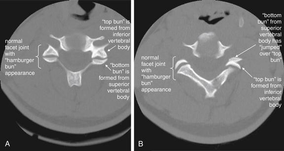
Figure 3-74 C2-3 unilateral facet dislocation (jumped facet).
Same patient as in Figure 3-73. The normal appearance of a cervical facet joint on axial CT images is a “hamburger bun.” The anterior (top) half of the “bun” is formed by the inferior cervical vertebra. The posterior (bottom) half of the “bun” is formed by the superior cervical vertebra. In a jumped facet, the superior articulating surface (bottom bun) jumps over the inferior articulating surface (top bun) and becomes anterior to it, reversing the normal configuration. A, A normal facet articulation bilaterally. B, The same patient, one cervical level higher. The patient’s right facet joint has a normal hamburger bun appearance, while the left facet joint has jumped, assuming a reversed hamburger bun appearance.
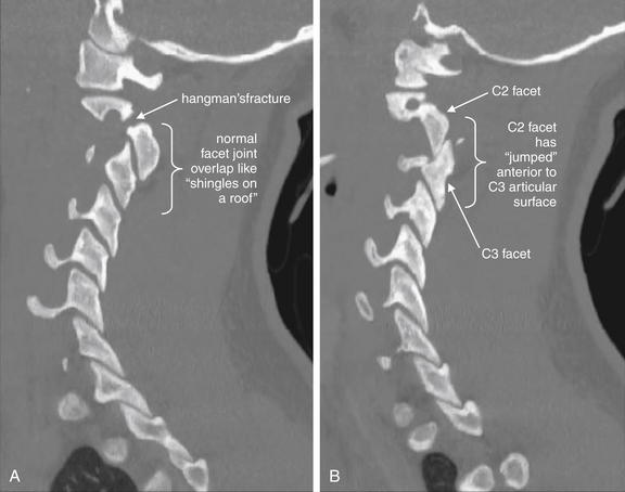
Figure 3-75 C2-3 unilateral facet dislocation (jumped facet).
Same patient as Figure 3-73 and 3-74. Parasagittal CT images. A, The patient’s right C2-3 facet joint is in normal position with appropriate overlap like shingles on a roof. B, A left unilateral jumped facet joint for comparison, with the superior articulating surface having moved anterior to the inferior articular surface. Injuries of this type require a substantial amount of force, and fractures often occur in association with jumped facets. This patient has a right hangman’s type fracture of C2 as well. Hangman’s fractures are explored in more detail in other figures. A jumped facet is more difficult to recognize on coronal views, which are not shown for this case.
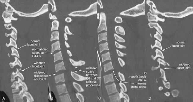
Figure 3-76 Cervical facet fracture and posterior subluxation with spinal cord injury.
In contrast to a jumped facet, in which the cephalad spine subluxes anteriorly relative to the caudad spine, posterior subluxation may occur. This sagittal CT series progresses from the patient’s right (A) to left (D). A and D, Note the widened facet joint at C6-7. B, The space between the spinous processes of C6 and C7 is also widened. B and C (a midline sagittal view), Posterior subluxation (retrolisthesis) of C6 on C7 is evident, narrowing the spinal canal. The distance between the C6 and the C7 vertebral bodies also appears wider than normal. Compare with the MRI in Figure 3-77.
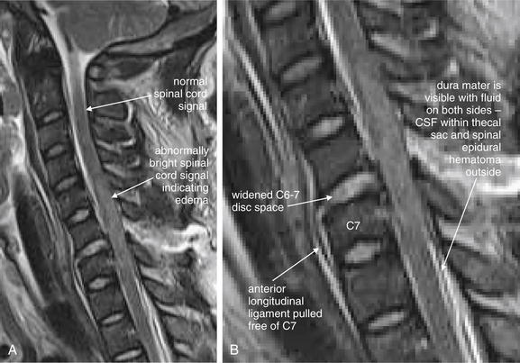
Figure 3-77 Cervical facet fracture and posterior subluxation with spinal cord injury.
A, This T2-weighted magnetic resonance image from the same patient as in Figure 3-76 demonstrates disruption of the posterior longitudinal ligament with widening of the C6-7 disc space. The anterior longitudinal ligament remains attached to the anteroinferior corner of C6 but has been stripped from the ventral surface of C7. B, Close-up.
There is an abnormal spinal cord signal from C4-5 through C7-T1 levels, with mild spinal cord expansion.
In addition, there appears to be large extramedullary fluid collection posterior to the spinal cord from the C7 level through below the field of view, displacing the thoracic spinal cord ventrally against the posterior longitudinal ligament. The dura is outlined by fluid signal intensity on both sides. CSF, Cerebrospinal fluid.
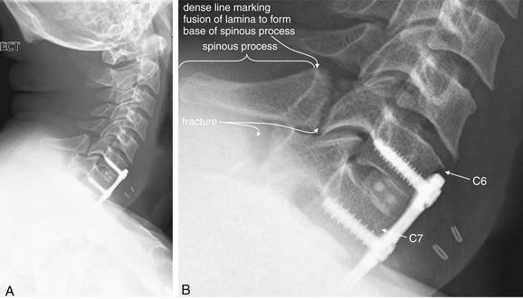
Figure 3-78 C6 and C7 laminar fractures.
A, This lateral x-ray reveals fractures through the lamina of C6 and C7. B, Close-up.
Look carefully at the images—the fracture line through C6 clearly runs anterior to the dense line marking the junction of the lamina with the spinous process. Fractures anterior to this line are lamina fractures, not spinous process fractures. Do not confuse lamina fractures, which can threaten the spinal cord, with spinous process fractures, which typically have little clinical consequence. The fracture line through C7 disrupts the dense line marking the anterior border of the spinous process. The x-ray is technically inadequate, because it shows the bottom margin of C7 but does not reveal the relationship with T1. The patient has hardware from a previous anterior spinal fusion. Compare with the CT in Figures 3-79 and 3-80.
A CDR goes through three important steps before it is ready for clinical application: derivation, internal validation, and external validation.
In step 1, called the derivation phase, the rule is developed. At this phase, many variables that might predict the presence or absence of a disease state are analyzed, and their contribution to the predictive value of the rule is calculated. Patients with and without the disease or injury in question (such as cervical spine fracture) are studied, and the presence or absence of each variable is recorded. Some variables may be found to have little predictive value and are discarded, while others may be highly predictive and are retained for the final rule. Sophisticated statistical techniques such as multivariate analysis allow the individual predictive characteristics of each variable to be assessed. The final rule must strike a balance among simplicity of application, sensitivity for detection of pathology, and specificity. A rule that is very sensitive and specific but has dozens of variables may be too cumbersome for clinical application. A rule that is simple and specific but insensitive cannot safely be employed, because it would limit testing to just those patients with disease but might miss many patients with pathology. A rule that is simple and sensitive but nonspecific would mandate testing of many patients without disease, at potentially great cost.
Following derivation, the limited number of variables that appear to constitute a simple, sensitive, and specific rule are retested to ensure that statistical chance did not result in their apparent predictive value. Remember that many variables are assessed in the derivation phase, because the researchers do not yet know which will have predictive value. This methodology is subject to the appearance of false chance associations between variables and endpoints. Conventionally, an association is considered to have statistical significance if the likelihood of the association occurring by chance is less than 5%. This corresponds to a p value of less than 0.05. When multiple comparisons or associations are tested, as is the case in the derivation phase, the probability of one or more associations meeting this threshold grows rapidly. When only one association is tested, the chance
Box 3-1 What Does Cervical Spine Computed Tomography Show?
Controversy exists about the screening value of CT in assessing spinal cord or ligamentous injury. Some authors advocate that a normal CT scan virtually eliminates these diagnostic possibilities, but MRI remains the diagnostic standard. The evidence for CT is discussed in the text.
of a p value below 0.05 is, by definition, 0.05 or 5%. This is like rolling a 20-sided die a single time: there is a 5% chance that the number 1 will be rolled, just by chance. But consider the chance of at least one association meeting this threshold as multiple associations are tested. This is equivalent to rolling the 20-sided die many times. It becomes increasingly unlikely that the number 1 will not be rolled at least once.
All of this is to say that, following the derivation phase, the apparent rule must be carefully tested, as some of
Box 3-2 When Should Cervical Spine Computed Tomography Be Performed?∗

∗ The ACR now recommends CT as the initial screening modality for all suspected acute cervical spine trauma in patients meeting imaging requirements by NEXUS or the CCR.
the apparent predictors may have occurred solely by chance. The more exhaustive the derivation phase, with more variables or associations being tested, the more likely that one or more of these associations is false, with no predictive value (or even the opposite predictive value of that determined in the derivation phase).
In step 2, the internal validation phase, the rule is retested in the same population (or a similar population) to that in which it was derived. If the rule retains its predictive value, it may be safely applied in that population henceforth. If the rule fails to perform as it did in the derivation phase, additional testing and refining of the rule is needed. If the rule withstands internal validation, additional external validation should be performed (step 3) before the rule is widely implemented in populations that differ from the initial population. These external validation phases may vary the patient population, the setting, or the medical practitioner applying the rule. For example, a CDR that works well when applied by emergency physicians in an emergency department in the United States might work poorly when applied by paramedics in the prehospital setting in another country. Well-validated CDRs are often testing in many settings to ensure that they are robust and impervious to variations of this type.
With this background, let’s return to the specific example of the Canadian Cervical Spine Rule (CCR). The CCR was derived and validated in Canada, and it has subsequently undergone additional external validation.7 The rule is somewhat more complex than the NEXUS criteria but boasts greater specificity, resulting in a greater decrease in cervical spine imaging. The original study was prospectively conducted in 10 Canadian medical centers, enrolling 8924 patients with blunt head and neck injury, stable vital signs, and a normal Glasgow Coma Scale (Box 3-5). It found 151 patients with cervical spine injuries, 1.7% of the enrolled population. The rule was 100% sensitive and 42.5% specific, resulting in an impressive 41.8% reduction in cervical imaging utilization.
The CCR and NEXUS have been prospectively compared in a study conducted by the authors of the CCR (Box 3-6).8 This study enrolled 8283 patients in nine Canadian medical centers, finding 169 patients with cervical spine injuries, constituting 2% of the population. The CCR outperformed NEXUS, with a sensitivity of 99.4% versus 90.7% for NEXUS. In addition, the CCR was
Box 3-3 The National Emergency X-radiography Utilization Study

45.1% specific, versus 36.8% for NEXUS. The Canadian authors have argued that NEXUS is insufficiently sensitive to be applied safely and that their criteria have the additional benefit of superior reductions in imaging use. The American authors of NEXUS have pointed to the outcome of this study as inconsistent with the original NEXUS study, which was conducted in a much larger population of some 30,000 patients. Why, they ask, did NEXUS perform with higher sensitivity in that setting? They argue that it is implausible that NEXUS has a sensitivity of only 90%, as this would have resulted in 80 missed cervical spine injuries in the original NEXUS study.
Box 3-4 The National Emergency X-radiography Utilization Study Criteria∗
∗ Violation of any one criterion mandates cervical imaging.
Which Criteria Should I Use: The National Emergency X-radiography Utilization Study or the Canadian Cervical Spine Rule?
Both NEXUS and the CCR are the result of well-conducted prospective clinical trials—level I evidence under the hierarchy used by the American College of Emergency Physicians (Table 3-3), which does not have a current clinical policy recommending the best CDR for evaluation of the cervical spine. The American College of Radiology (ACR) cites both rules as appropriate for evaluation of the need for cervical spine imaging in its appropriateness criteria.1 Application of either rule is appropriate.
TABLE 3-3 Levels of Scientific Evidence
| Class of Literature | Type of Study | Level of Recommendation |
|---|---|---|
| I | Randomized clinical studies using prospective data (or meta-analysis of the same) | A—high degree of clinical certainty |
| II | Nonrandomized trials or retrospective or case-control data | B—moderate degree of clinical certainty |
| III | Expert opinion or consensus; data from smaller, less well-controlled studies or case series; or both | C—guarded, inconclusive, or preliminary recommendations |
Can I Mix and Match the Rules?
It may be tempting to mix two well-validated rules in an attempt to capture the best features of both. Unfortunately, it is uncertain what the result of this strategy
would be. It is possible that mixing the two rules would decrease the specificity of both, resulting in a rule that, although quite sensitive, did not diminish use to the extent achieved by either rule alone. More research is needed to determine whether a combined rule would have better diagnostic performance.
Do the Rules Apply to Geriatric Patients?
Geriatric patients raise special concerns for cervical spine imaging. Do NEXUS and the CCR apply to these populations? NEXUS included 2943 patients age 65 or older, accounting for 8.6% of the study group. Cervical spine injuries occurred in 4.59% of this group, a rate
Box 3-6 The Canadian Cervical Spine Rule versus the National Emergency X-radiography Utilization Study
more than twice that in younger patients. Notably, 20% of injuries were odontoid fractures, compared with only 5% in younger patients.5 Certainly elderly patients in this study were a high-risk group—could the NEXUS CDR actually reduce use in this group? While popular conception might hold that it would be fruitless to apply a CDR to geriatric patients, in actuality a greater percentage of the elderly met the NEXUS low-risk criteria and avoided imaging: 14% of geriatric patients compared with 12.5% of younger patients. Following the NEXUS rule, only two cervical spine injuries were missed in older patients, both fitting into the predefined “insignificant” category. By this definition, NEXUS maintained 100% sensitivity in a geriatric population. When considering geriatric patients with blunt trauma, NEXUS can be applied safely. However, many elderly patients will require cervical CT, if they require any form of imaging, due to inadequate or abnormal x-rays demonstrating degenerative changes.
The CCR found age of 65 years or older to be a high-risk factor mandating imaging in its derivation set,7 and this was maintained as a mandatory criterion for cervical spine imaging in the multiple validation studies that have followed. Thus, for geriatric patients, application of NEXUS results in imaging of fewer patients than does the CCR.
Do the Rules Apply to Pediatric Patients?
NEXUS provides us with limited information about the pediatric population. In it, 3065 patients, 9% of the total NEXUS population, were younger than 18 years. However, only 88 children were younger than 2 years, 817 between the ages of 2 and 8, and 2160 children between the ages of 8 and 17. Only 30 patients under the age of 18 (0.98%) sustained any cervical spine injury, resulting in very wide confidence intervals (CIs) for the study results. Only 4 of the 30 injured children were under the age of 9, and no injured patient was younger than 2 years, so the study results should not be applied to children in these age-groups. Overall, the decision rule correctly identified all pediatric cervical spine injuries with a sensitivity of 100%. The small total number of injuries results in a lower 95% CI of 88%. Investigators concluded that cervical spine injuries are rare among patients 8 years and younger and that the NEXUS rule performed well in children, with the ability to safely eliminate imaging in approximately 20% of patients. The rule is probably very safely applied in children ages 8 and older, who form the largest portion of the study population.9
The derivation and validation studies for the CCR excluded patients younger than 16 years of age.7 One small retrospective study suggests poor performance of the CCR and NEXUS in children under 10 years, but larger multicenter prospective studies are needed to determine the performance of the CCR in young patients.7a
How Sensitive Are X-ray, CT, and Magnetic Resonance Imaging for Cervical Spine Injury?
Once a patient is determined to require cervical spine imaging, the best test for evaluation must be selected. Let’s examine the sensitivity and specificity of plain x-ray, CT, and MRI for acute cervical spine injury.
How Sensitive Is X-ray for Cervical Spine Injury?
Studies of x-ray sensitivity find markedly different results, depending on whether inadequate films are considered or whether these are excluded from analysis and only “adequate” x-rays are considered in calculating the false-negative rate. In addition, if x-rays are credited as “positive” for detecting any fracture, they appear to have relatively good sensitivity, whereas when x-ray sensitivity is discounted for second and third fractures found on CT, their sensitivity appears quite poor. The consensus among multiple studies is that cervical spine plain x-rays miss some fractures—with a pooled sensitivity of 52%, compared with 98% for CT, according to a meta-analysis of seven studies.10 As a consequence, the ACR has now advocated CT as the initial screening test for suspected cervical spine injury in adult patients, in place of x-ray. The ACR endorses no cervical spine imaging in patients meeting either the NEXUS or the CCR low-risk criteria. Certainly when high clinical concern exists for fracture, CT should be performed, often as the initial imaging study rather than x-ray. In a low-pretest probability patient with a normal cervical spine plain x-ray series, the risk of fracture is very low. Let’s examine some of the evidence behind these conclusions.
Holmes et al. performed a meta-analysis of cervical spine imaging studies to determine the sensitivity of plain x-ray and CT, and their results are largely the basis of the current ACR recommendation. The authors imposed fairly strict inclusion and exclusion criteria for studies (Table 3-4). Studies were considered if they were either a randomized, controlled trial comparing x-ray and CT or a cohort study of patients undergoing both x-ray and CT. Studies were excluded if the x-ray series did not include the AP, lateral, and open-mouth odontoid views; if the CT scan did not extend from the occiput to the superior aspect of the first thoracic vertebra; or if distance between CT scan slices exceeded 5 mm. The authors also assessed the methodologic quality of the studies, using the rating scale in Table 3-2. Among 712 studies identified by the authors in Medline, only 7 met the inclusion criteria, and none of those were rated as methodologic quality I or II. The authors used the published raw data from these 7 studies and calculated a pooled sensitivity of 52% for x-ray (95% CI = 47%-56%) and 98% for CT (95% CI = 96%-99%). The meta-analysis authors acknowledge the methodologic limitations of the available data and state that CT should be used as the primary tool for screening high-risk patients, although further study is needed to determine whether x-ray is adequate for evaluation of low-risk patients. Despite this, the ACR has adopted an all-or-none approach to cervical spine imaging in the adult acute trauma patient and does not differentiate between patients at higher and those at lower risk once the decision has been made to perform cervical imaging.
TABLE 3-4 Criteria Used to Select Studies for Inclusion in Meta-analysis of Cervical Spine Imaging
| Methodologic Quality | Criteria |
|---|---|
| I | Randomized controlled trials comparing CT with plain radiography |
| II | Nonrandomized studies, sample size > 50 subjects, with a representative sample and an independent gold standard |
| III | Nonrandomized studies, sample size < 50 subjects, minimal to moderate selection bias, or lacking an independent gold standard |
| IV | Nonrandomized studies, <50 subjects or severe selection bias |
Holmes JF, Akkinepalli R. Computed tomography versus plain radiography to screen for cervical spine injury: A meta-analysis. J Trauma 58(5):902–905, 2005.
Before accepting the results of this meta-analysis, let’s consider whether the authors’ criteria are reasonable and achievable. First, for cervical spine injury, what independent gold standard test should be used to confirm or rule out an injury, outside of CT? Clinical follow-up could be used but would only be useful for identifying injuries resulting in neurologic sequelae or surgical interventions, because stable fractures might heal uneventfully and not be appreciated on clinical grounds. Other imaging tests, such as MRI, could be used, but it is not clear that their results are a stronger gold standard than CT. Nonetheless, demanding an independent gold standard is essential when comparing x-ray and CT, as CT would otherwise be guaranteed the apparent better result. None of the studies included in this meta-analysis used a gold standard independent of CT results. Their use of CT as the gold standard represents incorporation bias and limits the validity of the studies and of the meta-analysis. Moreover, because no false-positive CT results are possible under this definition (because the CT result is considered correct in every instance), specificity and positive and negative likelihood ratios for CT cannot be determined. In addition to problems with the gold standard in the included studies, the studies suffer from spectrum bias as a consequence of inclusion of mostly badly injured patients at high risk of multilevel cervical spine injury. Holmes et al acknowledged these limitations and suggested that CT might not be necessary in all patients.
Were the authors too stringent in their inclusion criteria for studies to be considered? Note that the sentinel NEXUS and CCR studies, with more than 40,000 patients between them, were not included in this meta-analysis because neither study compared x-ray to CT scan in all patients. Both studies used a combination of imaging studies and clinical follow-up to determine if a patient had a clinically important cervical spine injury, rather than asking whether any fracture was present.
Let’s examine several additional studies, including some of those included in the meta-analysis. In a single-center study of 936 trauma registry patients over a 9-month period, 58 patients with cervical spine injuries (6.2%) were found. A substantial number of inadequate plain x-rays occurred. When considering only those cases in which a technically adequate plain x-ray series (three views of the cervical spine) was obtained, three false negatives occurred, resulting in a sensitivity of 90.3% and a specificity of 96.3% for x-ray. The positive predictive value of an adequate three-view series was 54.9%, with a negative predictive value of 99.5%.11 In a second retrospective single-center study of 3018 blunt trauma patients, 1199 patients underwent both x-ray and CT scan. In this study, 116 patients with injury were detected (9.5%), and 41 (3.2%) had false-negative x-rays. All required treatment—the authors concluded that CT rather than plain x-ray should be used to screen trauma patients.12-13 However, two limits of this study bear consideration. First, the average Glasgow Coma Scale score in patients with missed injuries was 12 and the average injury severity score (Box 3-7) was 14.6 (on a 0- to 75-point scale), so this was a population of moderately injured patients with altered mental status, not a population of alert and otherwise uninjured patients, which is a common scenario in which cervical spine evaluation is required. In addition, as in many studies, CT scan was the gold standard for diagnosis, and it automatically was credited with a sensitivity of 100%.
In a third, prospective study of 1356 blunt trauma patients with altered mental status, 95 injuries from C0 (skull base) to C3 were found in 70 patients (5.2%).
Box 3-7 Injury Severity Score Defined
Injury severity score values range from 0 to 75. Six body regions are considered, with the scores from the three most severely injured regions being squared and then summed.
From Baker SP, O’Neill B, Haddon W Jr, et al: The injury severity score: A method for describing patients with multiple injuries and evaluating emergency care. J Trauma 14(3):187–96, 1974
Plain x-ray found injuries in 38 patients (54%), while CT found injuries in 67 (96%).14 The remaining 3 injuries (4%) not detected on CT were recognized by clinical neurologic deficits, and represented spinal cord injury without radiographic abnormality (SCIWORA) (see later discussion).
A fourth, prospective study of 324 blunt trauma patients compared two protocols for assessment of the cervical spine. By protocol, patients requiring head CT underwent a single lateral cervical spine x-ray and cervical CT scan. If head CT was not clinically indicated, three views of the cervical spine were performed, with selective CT performed to evaluate areas not well seen on plain x-ray. Fifteen patients (4.6%) had cervical spine injuries, and x-ray had only 54% sensitivity compared with the gold standard of CT.15 The authors concluded that CT is the appropriate initial cervical imaging test in patients undergoing head CT.
Contrary to these studies is the largest dedicated prospective study of cervical spine injury and imaging—NEXUS. This study of 34,069 patients included 818 patients with injuries (2.4%). The gold standard in this study was review of all final radiology reports, including CT and MRI when available, and clinical follow-up. X-ray revealed 932 injuries in 498 patients and missed 564 injuries in 320 patients. But 436 missed injuries in 237 patients occurred in the context of an inadequate plain x-ray, or an x-ray that was in fact abnormal and revealed at least one cervical spine injury, though not all of the injuries that were ultimately discovered. When the definition of a false-negative x-ray was limited to a normal and adequate x-ray in the presence of cervical spine injury, 23 patients with 35 injuries were found, including three unstable cervical injuries. By this more limited definition of false negatives, x-ray had a sensitivity of 97%. The authors concluded that (1) inadequate x-rays mandate additional imaging and (2) rarely, normal x-rays miss injury.16
Should we accept the NEXUS authors’ definitions and believe their conclusions, or are they manipulating the data to defend x-ray? From a practical clinical standpoint, an x-ray that shows one fracture but misses a second fracture is true positive, not false negative. This conclusion is based on the premise that all abnormal plain x-rays will be followed by CT, which presumably will detect the second injury. So, if the purpose of x-ray is to screen for the presence of one or more injuries, this definition is fair. Excluding inadequate plain x-rays from analysis also makes sense from a clinical perspective, because an indeterminate test should not be relied upon to exclude an important diagnosis. The NEXUS authors’ take-home point is likely accurate—when normal and adequate x-rays are successfully obtained in a patient with a low pretest probability of injury, missed injuries are rare. The emergency physician should recognize patients with a high pretest probability of injury and those in whom inadequate plain x-rays are likely to be obtained and should choose CT as the first imaging test. In addition, the emergency physician must reject inadequate plain x-rays, recognizing the high risk of missed injury, and perform additional imaging (usually with CT) when these occur.
What Constitutes an Adequate Plain X-ray Series? Are Five Views Better than Three?
Traditionally, five views of the cervical spine were performed at many medical centers: the standard three views (AP, lateral, and odontoid) and bilateral oblique views. Do these additional two views improve the sensitivity of x-ray? In a single-center study of 1006 blunt trauma patients with altered mental status, 116 patients with 172 injuries were enrolled. All underwent five views of the cervical spine followed by CT. The five-view plain x-ray series missed 52.3% of injuries in 56% of patients, including 93% of occipital fractures and 47.2% of fractures from C1 to C3. The overall sensitivity of the five-view series was only 44%, with 100% specificity. The positive predictive value was 100%, with negative predictive value of 99.7%. The authors concluded that five views offer inadequate sensitivity and that CT is more appropriate in patients with altered mental status.6
How Sensitive Is CT for Cervical Spine Injury?
CT scan is believed to be nearly 100% sensitive for bony abnormalities or dislocation, although this conclusion is limited by the lack of a clear alternative gold standard. Because CT is generally considered superior to plain x-ray and even MRI for evaluation of bony abnormalities, a finding on CT is considered to be real—CT is 100% sensitive for fractures. Missed injuries on CT are generally restricted to isolated soft-tissue injuries, included cervical spinal cord injuries without fractures or subluxations. These injuries are called spinal cord injury without radiographic abnormality (SCIWORA).
Spinal Cord Injury Without Radiographic Abnormality
It has long been recognized that some patients with cervical spinal cord injuries did not have visible fractures, subluxation, or soft-tissue injuries on plain x-ray or, in later years, on CT scan. These injuries can rarely be missed despite modern multiplanar CT. Originally, SCIWORA was believed to be an injury seen predominantly in children,17-21 with the hypothesized reason being a more flexible cervical spine, one more prone to subluxation than to fracture. More recently, SCIWORA has been described in adults and may be as common in adults as in children—although it remains a rare injury pattern. NEXUS provides insight into the frequency of SCIWORA. NEXUS defined SCIWORA as spinal cord injury on MRI with complete and technically adequate plain radiographic series showing no injury. Of 34,069 patients, and 818 (2.4%) with cervical injuries, only 27 (0.08%) had SCIWORA—all adults. NEXUS included 3000 children, with 30 (1%) having cervical injuries, but no instances of pediatric SCIWORA were observed. The most common MRI findings of SCIWORA are shown in Box 3-8.22
Other studies continue to suggest a relatively high incidence of this disease among children with cervical spine injuries. A 10-year review of the National Pediatric Trauma Registry including 75,172 children found 1098 (1.5%) with cervical spine injury, among whom 83% had bony injury and 17% had SCIWORA. Of the 35% with neurologic injury, 50% had SCIWORA. Nonetheless, 17% of 1.5% would mean an overall incidence of 0.255% of child victims of blunt trauma experience SCIWORA. This study is also limited by a lack of CT data. Because CT results were not reported, it is possible that many of the cases of SCIWORA would have had abnormalities that could have been detected by CT.23 Overall, SCIWORA appears exceedingly rare; occurs in adults, as well as in children; and might be more accurately renamed spinal cord injury with only abnormal MRI.
How commonly does CT miss spinal cord injuries? In one study of trauma patients with altered mental status, CT identified injuries in 67 of 70 patients with spinal injury (96%). The remaining 3 patients had neurologic deficits attributable to C0 to C3 spinal cord injury.14 In a similar study of trauma patients with abnormal mental status, CT
Box 3-8 Most Common Magnetic Resonance Imaging Findings of Spinal Cord Injury Without Radiographic Abnormality
From Hendey GW, Wolfson AB, Mower WR, et al. Spinal cord injury without radiographic abnormality: results of the National Emergency X-Radiography Utilization Study in blunt cervical trauma. J Trauma 53(1):1–4, 2002.
sensitivity for cervical spine injury was 97.4% and specificity was 100%, with positive and negative predictive values of 100% and 99.7%, respectively. Again, by definition, CT only missed SCIWORA—in 2 of 116 patients (1.7%).6
Does a Normal CT Rule Out Soft-Tissue Injuries Such as Spinal Ligament Tears, Disc Protrusions, and, Most Importantly, Spinal Cord Injuries? Should Patients Remain Immobilized After a Normal Cervical Spine CT? Is Magnetic Resonance Imaging or Other Imaging, Such as Flexion–Extension X-rays, Required to Rule Out Additional Injuries?
CT scan is extremely sensitive for cervical spine injuries such as fracture and subluxation. The presence of prevertebral soft-tissue swelling implies possible ligamentous injury, and subluxation of vertebral bodies virtually guarantees ligamentous injury, although the spinal ligaments themselves are not well seen on CT. When sufficient injury has occurred to tear spinal ligaments, associated hemorrhage and soft-tissue swelling are expected to occur, increasing the thickness of prevertebral soft tissues. On CT, the width of prevertebral soft tissues is easily measured. Theoretically, if this tissue thickness is normal, ligamentous injury is quite unlikely, even if the ligament itself cannot be visualized. MRI is the test of choice if ligamentous injury is highly suspected, because the injured tissue can be directly visualized. By adjusting the window level on cervical spine CT, other soft-tissue detail such as spinal epidural hematomas and disc protrusions can sometimes be seen, although MRI remains the gold standard.
When no fractures, subluxations, or soft-tissue injuries are seen on CT scan, are soft-tissue injuries ruled out, or is MRI needed, as has been the standard for the past decade? Two common clinical scenarios may raise this issue in emergency medicine practice. First, in the obtunded or sedated trauma patient, in whom a reliable neurologic examination cannot be performed, is MRI required to rule out cervical soft-tissue injuries? While this is an important question, for most emergency physicians this is a decision deferred to trauma teams following admission. Several recent studies have addressed this question, and their results may help us to understand the second common clinical scenario, that of the awake and alert emergency department patient who continues to complain of neck pain following a normal cervical spine CT. Does this patient require further imaging, either with MRI or with flexion–extension x-rays, to assess for ligamentous injury? Let’s examine the results of some recent studies that may shed light on this topic.
Menaker et al.24 reviewed the Maryland trauma registry and identified 234 obtunded blunt trauma patients with normal cervical spine CT who underwent MRI for further assessment, following a clinical guideline. Of these patients, 18 (8.9%) had an abnormal MRI, including 2 who required surgical repair and 14 in whom extended cervical collar use was employed.
Stelfox et al.25 retrospectively studied 140 consecutive intubated patients before and 75 consecutive intubated patients after a change in protocol for cervical spine clearance in obtunded trauma patients at Massachusetts General Hospital. Before the protocol change, cervical spine immobilization in these patients was discontinued after normal findings on cervical spine CT with multiplanar reconstructions and one of the following: a reliable normal clinical neurologic examination (implying normalization of mental status), normal passive flexion–extension x-rays (which have been criticized because of risk of injury when the cervical spine of an obtunded patient is moved by a physician), or normal cervical spine MRI within 48 hours of admission. After the protocol change, normal CT findings alone were considered sufficient for cervical spine clearance. A normal CT was defined as one with no evidence of fracture, dislocation, subluxation, or indirect signs such as soft-tissue edema, inappropriate lordosis, or widening of the atlantodental distance. The study authors concluded that no missed cervical spine injuries were documented in either group. Does this prove that no injuries were present? No; in many of these patients, the neurologic examination may have remained uninterpretable because of concurrent injuries, such as traumatic intracranial injuries or anoxic brain injury. Cervical spine injuries could have been present but not recognized, and cervical spinal cord injuries resulting from discontinuation of cervical spine immobilization could have occurred but not been recognized or documented in the patient medical record. A stronger gold standard would have been helpful in proving that discontinuing cervical spine immobilization on the basis of CT findings alone is a safe practice. Assume for a moment that the authors are correct that no injuries were missed in the second group, of whom 70 had cervical spine clearance before death or discharge. If no injuries were missed in this group, the upper 95% CI limit of the actual missed injury rate can be estimated as 3 of 70 (a well-described estimation method for series with zero outcomes), or 4%. This would mean that a normal CT in this scenario predicts better than 96% chance of no cervical spine injury. We should be careful in accepting the authors’ contention, however. The possibility of unrecognized missed injuries casts doubt on the results of this study.
A third, similar study examined the results of cervical spine MRI performed in obtunded trauma patients following a normal cervical spine CT with a 16-slice scanner. Como et al.26 prospectively studied 115 obtunded blunt trauma patients at MetroHealth Medical Center in Cleveland, Ohio. They found that 6 of 115 patients (5.2%) had acute injuries identified on MRI that had not been recognized on CT, including microtrabecular bony injuries, intraspinous ligament injuries, a spinal cord signal abnormality, and a cervical spine epidural hematoma. The authors contend that none of these injuries changed patient management or required continued spine immobilization, though they admit limitations, including lack of long-term follow-up.19 The authors did not report the lower limit of their 95% CI, but using their reported data, the negative predictive value of CT could be as low as 89%. Tomycz et al.27 studied a similar population of 180 patients with normal cervical CT and found that 21.1% had abnormalities on MRI, none of which was unstable or required surgery. Similar limitations apply.
Sekula et al.28 reviewed the charts of 6558 patients admitted for blunt trauma. They identified 447 patients with cervical fractures. Among the remaining 6111 patients without fracture, they identified only 12 (0.2%) with injuries requiring surgical fixation or halo placement. The authors contend that all were diagnosable by findings on multidetector CT, although interestingly, 3 of 12 patients had injuries not recognized prospectively before MRI. The authors discount these as “misinterpretations” of CT. A more strict methodology would require that these 3 cases be counted as false-negative results, giving a sensitivity of only 75% (9 of 12) for CT in detection of unstable nonfracture injuries requiring stabilization. Moreover, the authors note that they had no follow-up on discharged patients who may have developed neurologic symptoms because of missed injuries.
Hogan et al.29 retrospectively reviewed the records of 366 obtunded patients at Maryland’s R. Adams Cowley Shock Trauma Center who had undergone normal cervical CT followed by MRI. MRI identified seven cervical cord contusions, four ligamentous injuries, and three intervertebral disc contusions. In this study, CT with a 4- or 16-slice scanner had a negative predictive value of 98.9% for ligamentous injury and 100% for unstable cervical spine injury. Although negative predictive values are generally discouraged as a means of presenting study results, as they are subject to change depending on the prevalence of injury in the population, these figures are impressive given the high-risk population in this study. The study did not report CT sensitivity, as the denominator of all patients with cervical spine injuries was not studied, only those with negative CT.
Smaller studies provide conflicting results. Stassen et al.30 found that up to 30% of patients had cervical spine ligamentous injuries on MRI, when no fractures were detected on eight-slice cervical CT. The significance of these injuries is uncertain. Adams et al.31 found no additional cervical spine injuries in 20 obtunded patients with normal CT.
How do these studies affect the management of the awake and alert patient with continued neck pain after a normal cervical CT? In general, these studies imply a very low rate of unstable cervical spine injury following a normal cervical spine CT scan. The populations studied are very high risk for injury, as the patients are intubated and obtunded, multiply injured patients at level I trauma centers. It is likely that cervical spine clearance following a normal CT would be even safer in an awake and alert patient with no other significant injuries. The current practice of immobilization until resolution of symptoms or clearance with flexion–extension x-rays has little evidence basis, although it carries the weight of long-held practice. Future higher-quality studies with strict gold standards (CT and MRI in all patients) and adequate follow-up would bolster the evidence at hand. Ideally, these studies would report sensitivity and specificity for CT by including in the studies not just patients with normal CT but all patients being evaluated with CT and MRI for cervical spine injury.
The studies we have discussed do demonstrate that rarely CT misses soft-tissue cervical spine injuries. Consequently, patients who complain of neurologic abnormalities such as weakness, numbness, or parethesias after a normal CT scan should continue to be evaluated with MRI.
What Is the Value of Flexion–Extension Views of the Cervical Spine? Do They Assist in Identifying Ligamentous Instability?
Flexion–extension views (see Figure 3-18) historically have been performed to evaluate for ligamentous instability once fracture has been “ruled out” by x-ray or CT. Flexion–extension views are contraindicated when an unstable fracture pattern or subluxation is evident on prior imaging (plain x-ray or CT), or when a patient has neurologic signs or symptoms, as motion of an unstable cervical spine may result in cervical spinal cord injury. Flexion-extension views consist of lateral x-rays of the patient’s cervical spine in active flexion and active extension. Active in this case means the patient must consciously and without assistance flex and extend the cervical spine. It is assumed that the patient will not worsen spinal cord injury, because increasing pain or neurologic symptoms will be warning signs to the patient to halt further flexion or extension. Passive flexion and extension, in which the patient’s cervical spine is physically manipulated into flexion and extension by a second person, should never be used; this may cause cervical spinal cord injury, because warning signs of pain or neurologic dysfunction might not be heeded quickly enough by the manipulator.
How might flexion–extension views detect ligamentous injuries? The spinal ligaments are not visible on plain x-ray, but torn, avulsed, or stretched spinal ligaments would presumably allow an abnormal degree of subluxation of one vertebral body relative to adjacent bodies. The acceptable degree of normal subluxation may vary with the age of the patient. In children under age 8, pseudosubluxation of up to 40% occurs in up to 40% of patients at the C2-3 level and in up to 14% of patients at the C3-4 level.32-33 Pseudosubluxation should be visible in flexion but should resolve or diminish in extension views. Subluxation in extension likely represents real pathology. Swischuk’s line, a line from the anterior portion of the C1 spinous process to the same point on the C3 spinous process, can assist with differentiation of pseudosubluxation from subluxation.33 The anterior portion of the C2 spinous process should be within 2 mm of this line. In addition, no significant prevertebral soft-tissue swelling should be seen with pseudosubluxation.
In an adequate normal flexion–extension series, the patient flexes and extends and no abnormal subluxation is seen. Normally, the disc spaces should widen by no more than 1.7 mm, and the vertebral bodies should not translate by more than 1 mm. The inferior endplates of two adjacent vertebral bodies should not display greater than 11 degrees of angulation. If abnormal subluxation is noted or if neurologic symptoms develop, MRI is indicated (Box 3-9). If pain prevents adequate flexion and extension, MRI may be performed, or the patient may be left immobilized in a cervical collar for several days, with flexion–extension views repeated when the patient’s pain has subsided to a sufficient degree. Caution should be exercised when obtaining flexion–extension views long after the injury; theoretically, it would be possible for the pain and swelling of an unstable ligamentous injury to have resolved completely, and the patient could experience a dangerous degree of
subluxation during flexion–extension imaging, resulting in spinal cord injury.
Does evidence support the practice of obtaining flexion–extension views? Subgroup analysis from NEXUS found that flexion–extension x-rays revealed only two stable fractures and four subluxations in 86 patients undergoing these additional views. The subluxation injuries were found in patients with other abnormalities already noted on neutrally positioned x-ray. The authors concluded that flexion–extension x-rays add little to the standard three views of the cervical spine—although this subgroup analysis includes too few patients to provide strong evidence.34
A retrospective review of 106 consecutive, awake, blunt trauma patients evaluated with flexion–extension x-rays found that 32 patients (30%) had nondiagnostic studies due to inadequate flexion and extension and 4 of these patients (12.5%) had cervical spine injuries subsequently diagnosed by CT or MRI. In contrast, only 5 of the 74 patients (6.75%) achieving adequate range of motion on flexion–extension views were found to have cervical injuries, all detected with flexion–extension. This study is quite limited by its small numbers and the lack of a uniform gold standard. Although the authors asserted that adequate flexion–extension x-rays missed no injuries, many patients did not undergo further definitive imaging, a methodologic flaw called workup or verification bias.35 The authors suggested that limited ability to perform flexion and extension on physical examination should indicate that flexion–extension x-rays not be performed, as they are likely to be nondiagnostic. They also concluded that additional cross-sectional imaging with either CT or MRI should be performed in patients who cannot perform flexion and extension after normal neutral x-rays, because this may be a marker of undetected injuries. Larger studies are required to confirm or refute this recommendation. The ACR states that the limited sensitivity and specificity of flexion-extension x-rays and the rarity of technically adequate x-rays make them almost useless in trauma patients. The ACR does suggest a role for flexion-extension x-rays in evaluation of potential ligamentous injury in patients with equivocal MRI, with abnormal ligament signal but no clear disruption.1 As described earlier in the discussion of CT for cervical spine clearance, flexion–extension x-rays are also likely unnecessary after a completely normal cervical CT with no soft tissue abnormalities noted.
Is There a Role for Fluoroscopy in Assessing for Unstable Cervical Spine Injuries?
Fluoroscopy has been suggested as a means of detecting ligamentous injury of the cervical spine in patients with altered mental status,36 but critics strongly discourage the use of fluoroscopy for this purpose. Passive manipulation of the cervical spine during fluoroscopy can result in cervical spine cord injury and should never be used. In a study of 301 obtunded trauma patients, only 2 patients (0.7%) had ligamentous injury detected by fluoroscopy, and 1 patient developed quadriplegia.37 Fluoroscopy shows bones but not soft tissues. It can detect ligamentous instability by revealing subluxation in real time, giving indirect evidence of ligamentous injury. Unfortunately, as the ligamentous injury is revealed on fluoroscopy, cervical spinal cord injury may be occurring, because the obtunded patient cannot complain of neurologic symptoms or pain. MRI should be used to evaluate for ligamentous injuries, because it does not carry this risk.
Do Cervical Spine Injuries Predict Arterial Injury? When Should Imaging of Cervical Arteries Be Performed, Following Detection of Cervical Spine Injury?
Sometimes cervical CT demonstrates fractures involving the transverse foramen, the bony channels housing the vertebral arteries. In other instances, subluxations or rotatory injuries of the cervical spine may shear or stretch these vessels, potentially causing vascular tears. Do these injuries predict an increased risk of arterial injury? In a retrospective study, 92 of 605 patients (15%) evaluated with angiography for cervical arterial injury after blunt trauma were found to have arterial injuries. Of these 92 patients, 71 (77%) had an associated cervical spine injury. Of these spine injuries, 55% were subluxations, and 26% were fractures involving the transverse foramen. Most of the remaining spinal injuries associated with cervical arterial injury were injuries to C1 through C3. Does this study indicate that all high cervical spine fractures, subluxations of the cervical spine, or transverse foramen fractures should be followed with evaluation of cervical arteries? Blunt vertebral artery dissection is associated with stroke, which is perhaps prevented by anticoagulation therapy. When these types of cervical spine injury are present, arterial imaging appears warranted based on current evidence.38 Arterial injuries are discussed in more detail in Chapter 4.
When Should CT Be the Initial Cervical Spine Imaging Modality, Rather Than X-ray?
The ACR now recommends a CT-first strategy in all adult patients with suspected cervical spine injury, as discussed earlier. If a technically adequate x-ray series can be obtained in a low-risk patient, x-ray can be used to screen for fracture, as it has been used for the past century. CT is the clear preferred first-line imaging technique in patients with high likelihood of cervical spine injury, in patients with multiple other injuries requiring CT for evaluation, in patients in whom rapid cervical spine clearance is especially desirable (e.g., to allow unusual positioning in the operating suite for treatment of other injuries), and in patients with a low likelihood of adequate plain x-ray, such as the elderly, obese patients, and patients with short necks, extensive cervical spine degenerative joint disease, prior injuries to the cervical spine that might be confused with acute injuries on plain film, and bone disorders such as ankylosing spondylitis (see Box 3-2).
Can Computed Tomography Detect Spinal Cord Injury and Nontraumatic Spinal Cord Abnormalities?
MRI, not CT, is considered the test of choice for spinal cord injury. CT shows secondary findings suggesting cord impingement, such as narrowing of the spinal canal from fracture fragments or subluxation of vertebral bodies. In some cases, the cord can be seen, but its tissue density is similar to that of cerebrospinal fluid, making detailed inspection difficult. A special technique called CT myelography (CT myelogram) is an alternative to MRI for visualization of the spinal cord. In CT myelography, contrast material is injected into the spinal canal through a spinal needle in a technique similar to diagnostic lumbar puncture. CT is then performed, and the spinal cord and nerve roots can be seen in relief against the contrast material outlining them. This technique is not commonly used but can be used in patients with contraindications to MRI. CT myelography provides information about spinal cord compression but does not provide information about intrinsic spinal cord pathology such as transverse myelitis, spinal cord infarction or edema, and multiple sclerosis. This type of pathology requires the soft tissue contrast of MRI.
How Long Does Cervical Computed Tomography Take to Perform? Which Is Faster, X-ray or Computed Tomography?
CT is the most time-efficient method of imaging the cervical spine. Daffner39 measured the time required to perform six views of the cervical spine (AP, lateral, open-mouth odontoid, bilateral obliques, and swimmer’s view) and found the average to be 22 minutes (range of 5 to 46 minutes). Many patients required at least one view to be repeated to achieve a satisfactory image. In the same study, and again in a separate study, Daffner measured the time required for cervical spine CT and found the average to be between 11 and 12 minutes (range of 3 to 35 minutes), depending on whether the cervical CT was performed in conjunction with a head CT.39-40 These results were achieved using a 4-slice scanner, and imaging times with newer scanners are even faster. A 64-slice CT can perform sixty-four 0.625-mm slices per second, meaning that in each second of scanning, a territory 40 mm (64 × 0.625 mm) in length can be imaged. If the cervical spine is 20 cm (200 mm) in length, CT could be completed in 5 seconds. In addition, CT has the advantage of performing cervical spine imaging in the same location that diagnostic imaging for other injuries is being performed. Even if only three x-ray views of the cervical spine were performed, halving the time for x-ray, CT is faster with modern scanners.
Radiation
The radiation doses for cervical spine x-rays and CT differ by an order of magnitude.
A three-view cervical x-ray series (consisting of an AP, a lateral, and an open-mouth odontoid view) generates about 0.1 mSv, although the dose may rise if additional views or repeated attempts at the same view are needed to obtain diagnostic-quality x-rays. CT of the skull base and upper cervical spine for odontoid evaluation creates an effective dose of about 4.4 mSv using a single-slice scanner and about 2.3 mSv using a 16-slice scanner. CT of C0 to C3 and the cervicothoracic junction creates a dose of about 7.1 mSv using a single-slice scanner and 4.3 mSv for a 16-slice scanner. CT of the entire cervical spine generates a dose of 8.2 mSv using a single-slice scanner and 5.4 mSv for a 16-slice scanner.54 Substantial thyroid radiation exposures occur with cervical spine CT. Estimates of lifetime attributable mortality from complete cervical CT are in the range of 1 in 2400 for a single-slice scanner and 1 in 3700 using a 16-slice CT scanner. Attributable mortality estimates may vary with age at exposure, with younger patients incurring greater risk. Improvements in CT will likely reduce the effective dose, but significant radiation doses will likely remain using CT.41
Cost of Cervical Imaging
Cost-effectiveness of cervical radiography and CT have been compared in models with estimates based on patient pretest probability of injury, assumptions about the cost of missed injuries and resulting health care costs to society, and the direct costs of imaging.42-43 Blackmore42 found that high- and moderate-risk patients should be imaged with CT as the most cost-effective strategy. In low-risk patients, CT screening would be predicted to identify additional potentially unstable injuries, but the cost per quality-adjusted life-year would be greater than $80,000—making x-ray the more cost-effective strategy in this group. Like all cost-effectiveness analyses, this report may be subject to many inaccuracies due to potentially false assumptions about the sensitivity of x-ray and CT, the incidence of injury, the direct costs of imaging, and the costs associated with missed injuries. In a second cost-effectiveness analysis with similar suppositions about sensitivity, likelihood of injury, and costs, Grogan43 found CT to be more cost-effective than x-ray. According to that analysis, CT would have an institutional cost of $554 per patient, compared with $2142 per patient for x-ray, when the costs of missed injury settlements are included. Sensitivity analysis showed that x-ray could be more cost-effective if CT costs more than $1918 or if x-ray has a sensitivity greater than 90%.
Magnetic Resonance Imaging of Spinal Soft Tissue Injuries
MRI is the imaging modality of choice for patients with suspected spinal cord, nerve root, spinal ligament, or intervertebral disc injuries. MRI has outstanding soft-tissue contrast that allows direct visualization of these injuries. Ironically, MRI yields poor images of bone, as calcified bone has a paucity of protons to interact with the imposed magnetic field. MRI relies on the radiofrequency signal produced by protons subjected to a magnetic field. Tissues containing water and fat yield a strong MRI signal due to their high proton content. Bone contains little water or fat and consequently has poor proton content and MRI signal. Consequently, CT is an important complementary study to evaluate for spinal fractures. Typically, MRI sequences for traumatic injuries include transverse (axial) and sagittal T1- and T2-weighted fast spin–echo sequences. Short T1 inversion recovery images may also be acquired. Gadolinium contrast is not needed for evaluation of acute traumatic injury. Boxes 3-10 and 3-11 summarize indications for spine MRI and pathology that can be detected.28
How Sensitive Is Magnetic Resonance Imaging for Detection of Soft-Tissue Injuries of the Spine?
Physics of MRI, common MRI sequences, and evidence for MRI are discussed in detail in Chapter 15. Good-quality studies of the sensitivity of MRI for detection of soft-tissue injuries require an independent gold standard. Because other imaging studies are felt to be inferior to MRI, these standards usually include either clinical follow-up or reports from pathology or autopsy findings. It may come as a surprise that when MRI is compared with a strong gold standard such as autopsy, it has poor sensitivity for soft-tissue injury. A study comparing MRI of 10 adult accident victims with autopsy thin sagittal sections showed that MRI detected only 11 of 28 spinal lesions (39%)—mostly soft-tissue injuries, including facet joint capsule injuries, ligamentous injuries, disk injuries, and spinal cord lesions. In the same study, x-ray identified only 4% of lesions.44 Jonsson et al.45 performed an autopsy study comparing x-ray to cryosectioned cervical spine and found that x-ray detected only 1 of 10 gross upper cervical spine ligamentous disruptions. The clinical significance of the missed findings is impossible to assess from autopsy,
and MRI is currently our best imaging modality for this purpose, as x-ray shows extremely low sensitivity in the same studies (Boxes 3-10 and 3-11).
Imaging the Cervical Spine in the Absence of a History of Trauma
Emergency imaging of the cervical spine is less commonly indicated in the absence of a history of trauma. However, when spinal cord compression is suspected in the absence of trauma, plain x-rays play a relatively minor role in the evaluation. They have limited sensitivity and specificity for the soft-tissue abnormalities typically at play, such as cervical disc herniation, syrinx, neoplastic mass, and cervical epidural abscess. X-rays may suggest a bony lesion, such as a metastatic lytic lesion or cervical stenosis, but soft-tissue abnormalities can occur without any x-ray findings, and further imaging is always required if a high clinical suspicion is present. CT scan can be useful, as it remains highly
Box 3-11 When Should I Order Spine Magnetic Resonance Imaging?
sensitive for bony abnormalities, but often MRI is the first and only test required in the absence of trauma. MRI of the cervical spine is performed with gadolinium contrast when possible to evaluate the cervical spinal cord, discs, and surrounding epidural space. Gadolinium assists in detection and characterization of inflammatory, infectious, and neoplastic processes. However, cord compression can be identified without gadolinium if the patient has contraindications to gadolinium, such as poor renal function.
Cervical Spine Infections and Metastatic Disease
Unlike the case in traumatic cervical spine injuries, no clear CDRs exist, although some risk stratification can be performed. Because acutely dangerous spontaneous cervical spine pathology such as spinal cord compression from epidural abscess or hematoma or spinal and epidural metastases is relatively rare, typically many patients will require screening to identify a single case. Early identification of a lesion—before significant neurologic deficits have occurred—is extremely important, because neurologic deficits are often irreversible once present.46 Risk factors for cervical epidural abscess include preexisting minor spinal pathology such as spondylosis, degenerative joint disease, previous laminectomy, or nonpenetrating trauma from a fall or motor vehicle collision. Underlying diseases may predispose patients to develop cervical epidural abscess, including diabetes mellitus, alcoholism, cancer, chronic renal failure, and other compromised immune states. Injection drug use is a significant risk factor, and patients may not reveal a history of cervical injection in 50% of cases.47-48 Cervical osteomyelitis has been reported as a complication of cervical injection.49-50 Other recent infections, including distant sources such as urinary tract infection or skin abscesses, can lead to cervical epidural abscess by hematogenous inoculation. Any previous invasive spinal procedure, even several months before presentation, should increase the suspicion of cervical epidural abscess. Patients typically will not offer this information unless asked specifically. Several reviews suggest that almost 20% of patients will have no identifiable predisposing factors for cervical epidural abscess.51-52 Fever may not be present—reviews on this topic suggest fever is noted in only 30% to 80% of patients on presentation.53-55 The classic triad of localized spine tenderness, progressive neurologic deficits, and fever occurs in only 37% of patients with cervical epidural abscess.56
Imaging the Thoracic and Lumbar Spine
We now review epidemiology, decision rules, and imaging modalities for the thoracic and lumbar spine. Many of the same considerations discussed for cervical spine imaging apply. The ACR now recommends that CT of the thoracic and lumbar spine, rather than x-ray, be the initial screening test in blunt trauma patients requiring imaging of these regions. Images may be acquired from dedicated CT of these regions or from CT of the chest, abdomen, and pelvis obtained for evaluation of other injuries to these regions. The ACR recommends that the CT images include axial, sagittal, and coronal reformats,1 because these improve detection of injuries in the axial plane, including fractures and subluxations. Because patients with low-energy trauma mechanisms may still be evaluated with plain x-ray, we will review both x-ray and CT interpretation.
Introduction to Thoracic and Lumbar Spine Injuries
Thoracic and lumbar spine injuries are common following high-energy blunt trauma. In motorcycle collisions, thoracic spine injuries actually outnumber cervical injuries, accounting for 54.8% of spinal injuries in one large study.57 Overall, thoracic and lumbar spine injuries together account for more than half of all spinal injuries in car and motorcycle collisions, and multilevel injuries frequently occur. Falls from significant height account for another common presentation often requiring thoracic and lumbar spine imaging. Delays in diagnosis are common, occurring in as many as 19% of thoracolumbar injuries, implying a need for better clinical criteria to detect these injuries.58
How Are X-rays of the Thoracolumbar Spine Interpreted?
X-rays of the lumbar and thoracic spine are interpreted with many of the same considerations as those for cervical spine radiographs. The standard views of the thoracic spine are AP and lateral, whereas the standard lumbar views are AP, lateral, and a spot view of L5 to S1 to allow adequate penetration while limiting radiation exposure.
On the AP view (see Figure 3-86), the thoracic spine should be assessed for alignment of adjacent vertebral bodies. The pedicles are usually visible like the “eyes of an owl,” with the posterior spinous process present in the midline as the owl’s beak. The posterior spinous processes may be displaced from the midline when fracture or subluxation is present. Pedicles may appear asymmetrical because of fracture or may be eroded by lytic processes such as spinal metastases and infection. The transverse processes should be inspected for fractures. Paraspinous soft-tissue masses or hematomas may be evident as asymmetrical densities, and their presence can suggest fracture, even when a fracture is not directly visualized. The heights of vertebral bodies should be equal on the AP projection, and the space between vertebral bodies should be even. Compression fractures of vertebral bodies can decrease their height, and disc injuries can decrease the space between adjacent bodies.
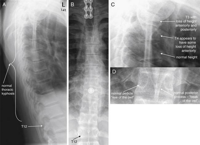
Figure 3-86 T2 corner avulsion fracture (extension teardrop) with T3 and T4 compression fracture.
A, Lateral thoracic spine x-ray. B, Anterior–posterior thoracic spine x-ray. C, D, Close-ups from A and B, respectively.
On a lateral view, each vertebral body should appear nearly rectangular, with similar height along its anterior and posterior borders. Anterior loss of height or “wedging” is common with compression fractures. Each body should appear similar in height to adjacent vertebra. The alignment of vertebral bodies should be assessed and should follow a slight thoracic kyphosis. Inspect carefully for any subluxation indicating injury. On the AP view, each vertebral body has two visible pedicles laterally (resembling the eyes of an owl) and a posterior spinous process in the midline (resembling an owl’s beak). Fractures, dislocations, or malignant lytic lesions can disrupt this normal symmetrical radiographic anatomy. The alignment of vertebral bodies should be smooth, and the height of each body should be similar to that of the adjacent vertebrae. Fractures in the high thoracic spine can be extremely difficult to detect on x-ray because of the overlap with other thoracic structures, including scapula, ribs, soft tissues of the chest, and upper extremities. CT is more sensitive and is indicated when significant injuries are suspected. Low energy compression fractures such as from falls from standing may not require CT confirmation.
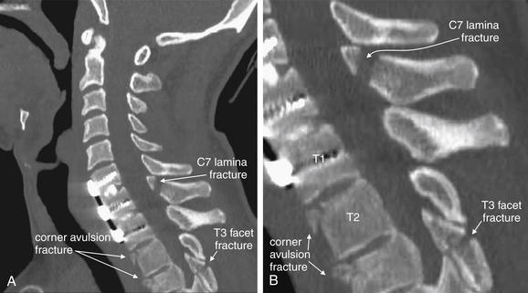
Figure 3-87 T2 corner avulsion fracture (extension teardrop).
A, Sagittal CT image of the cervical spine in the same patient as in Figure 3-86 revealed anterior corner fractures of T2 and T3 (incompletely seen at the lower margin of the cervical spine CT). B, Close-up. He has previously undergone anterior fusion of C6, C7, and T1, perhaps contributing to this injury. The typical findings are triangular (teardrop) avulsion fragments, usually described as being due to the anterior longitudinal spinal ligament pulling away bone at its attachment points during hyperextension of the cervical spine. Whether this is the true mechanism is uncertain—in this patient, hyperflexion appears more likely, as the subsequent figures show the affected vertebrae to have findings of compression. More frequently, corner avulsion injuries occur in the cervical spine and result in teardrop fragments at the inferior corner of the vertebral body, rather than at the superior margin, as in this patient. Additional fractures are visible, including a T3 facet fracture and C7 lamina fracture. These are discussed in detail in other figures.
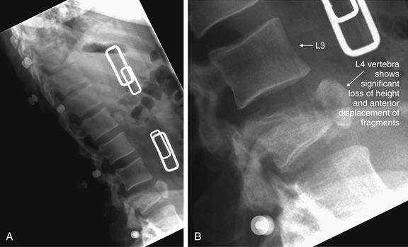
Figure 3-88 Thoracolumbar spine compression fracture.
A, This patient has an L4 compression fracture, seen well on this lateral x-ray. B, Close-up.
The anterior–posterior x-ray is less revealing (Figure 3-89). Computed tomography (CT) (Figures 3-90 through 3-92) revealed an unstable fracture. Note the normal L3 vertebra.
On the lateral x-ray (see Figure 3-86), the normal thoracic spine has a slight kyphosis, which should be a gradual and continuous curve. If the anterior margins of adjacent vertebral bodies do not align, subluxation is present; fractures may also be present. The upper thoracic spine is usually difficult to see on the lateral x-ray due to overlying shoulders. Swimmer’s views can assist in revealing upper thoracic spine pathology. The spinal level involved can be determined by counting up from the 12th rib on the AP projection. Children often have a normal variant that may be mistaken for an avulsion fracture on the lateral view. These are apophyses, small densities on the anterior superior and anterior inferior margins of adjacent vertebral bodies, which have the same appearance as anterior avulsion fractures in adults. Wedge compression fractures of the thoracic spine are common and result in decrease in the height of the anterior portion of a vertebral body relative to the posterior portion. Burst fractures can result in retropulsion of fragments into the spinal canal, and fragments may be seen on the lateral view posterior to the vertebral bodies.
The normal lumbar spine has a slight lordosis (see Figure 3-89), which should be smooth and continuous. Other features of the lumbar spine are generally similar to those described earlier regarding the thoracic spine.
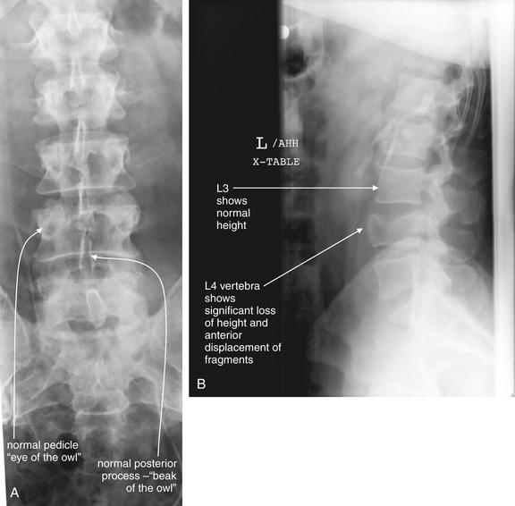
Figure 3-89 Thoracolumbar spine compression fracture.
Same patient as in Figure 3-88. This patient has an L4 compression fracture, seen well on lateral x-ray (B). The anterior–posterior x-ray is less revealing (A). CT (Figures 3-90 through 3-92) revealed an unstable fracture.
What Findings Suggest an Unstable Thoracolumbar Injury? What Is the Three-Column Concept?
Radiologists and spine surgeons (orthopedists and neurosurgeons) use a three-column concept to describe thoracolumbar spine injuries and to predict their stability. Although described first for the thoracic and lumbar spine, the three-column system can also be applied to cervical spine injuries. For emergency physicians, it may often be sufficient to recognize that an injury is present. However, understanding the potential for an unstable fracture can be helpful in protecting the patient from neurologic injury, in ordering follow-up studies, and in engaging a consultant. Denis described a three-column system of classification in 1983, based on retrospective review of 412 thoracolumbar injuries (see Figure 3-85). Previously, an anterior column (consisting of the anterior longitudinal ligament, marked on x-ray by the anterior borders of vertebral bodies) and a posterior column (consisting of posterior spinal ligaments) had been described. Denis59 added a middle column, formed by the posterior border of the vertebral body, the posterior longitudinal ligament, and the posterior annulus fibrosis of the intervertebral disc. The same year, a CT description of the middle column was published, and CT findings have become the basis for operative treatment decisions, though these are outside the scope of this text.60
When two of three columns are disrupted, the spine is considered unstable. Whether reviewing x-ray or CT images, inspect the three columns for fractures or malalignment. Injuries to more than one column should be considered unstable; however, x-ray is relatively insensitive for thoracolumbar fracture (see later discussion) and spinal precautions should be maintained even when only one column appears injured on x-ray. CT should be obtained for further evaluation. Injuries to more than one column usually involve failure of the middle and anterior columns, the middle and posterior columns, or all three columns.61 Injuries to anterior and posterior columns sparing the middle column are rare. Injuries to the anterior and posterior columns are often obvious. Middle-column injuries can be more subtle, but findings include widening of the pedicles, loss of posterior wall height greater than 25%, or obvious fracture of the cortex of the posterior vertebral body. For subluxation injuries without apparent fracture, translation greater than 3.5 mm or angulation greater than 11 degrees suggests column failure due to ligamentous injury.61
How Is Computed Tomography of the Thoracolumbar Spine Interpreted?
Interpretation of CT of the thoracolumbar spine follows the principles we described for cervical spine CT. Bone windows should be inspected in sagittal, coronal, and axial planes (see Table 3-2). Inspection of the sagittal images is extremely helpful for detection of anterior–posterior subluxation, as well as loss of height from compression fractures. The sagittal and axial images are useful for identifying retropulsion of fracture fragments into the spinal canal (see Figures 3-86 through 3-101). The coronal images are useful for assessing loss of height of vertebral bodies and disc spaces, lateral subluxation injuries, burst fractures with spread of fragments, and transverse process fractures. The sagittal images are particularly useful for assessing the three columns described earlier. All three series should be inspected to maximize detection of injuries, because fractures parallel to a given image plane will not be seen in that plane but are readily identified in images reconstructed in perpendicular planes. Anterior–posterior subluxation is best seen in sagittal images, whereas lateral subluxation is best seen in coronal views.
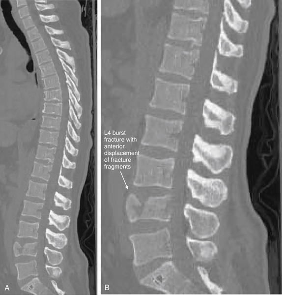
Figure 3-90 Thoracolumbar spine compression–burst fracture.
Same patient as in Figures 3-88 and 3-89. A, Sagittal CT shows L4 compression fracture, with loss of height of L4 vertebral body and slight radial spread of fragments. B, Close-up.
The anterior margin of L4 is not aligned with the bodies above and below. The posterior margin is displaced slightly into the spinal canal.
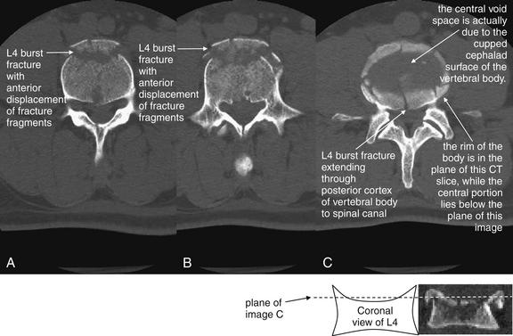
Figure 3-91 Thoracolumbar spine burst–compression fracture.
Same patient as in Figures 3-88 through 3-90. Axial computed tomography views of the same lumbar (L4) burst fracture. Note the radial dispersion of the fracture fragments. A to C are arranged from caudad to cephalad. The central void in C is due to the cupped cephalad surface of the vertebral body (see diagram). The center of the vertebral body lies below the plane of C, while the raised rim lies in the plane of C. This is an unstable fracture because it involves all three columns of the spine.
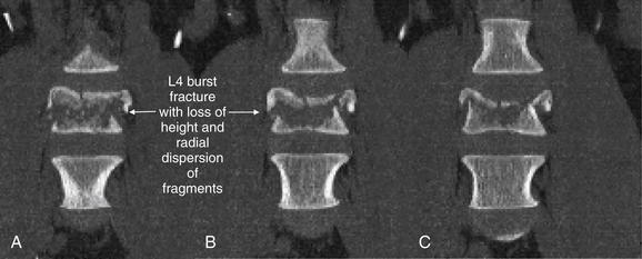
Figure 3-92 Thoracolumbar spine burst–compression fracture.
Same patient as in Figures 3-88 through 3-91. These coronal CT views demonstrate the significant loss of height and comminution of L4.
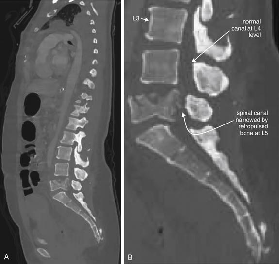
Figure 3-93 Thoracolumbar spine trauma: L5 burst fracture with cord compression.
This 39-year-old female was ejected from a motor vehicle and sustained an L5 burst fracture. Due to retropulsion of bone fragments into the spinal canal, she had no motor function and minimal sensation after this injury.
A, Sagittal CT view showing significant narrowing of the spinal canal at L5 due to retropulsion of fragments of the burst L5 vertebral body. B, Close-up. The L5 vertebral body is also shortened substantially compared with L3 and L4 due to a compression injury mechanism. Compare with the axial and coronal CT images in Figures 3-94 and 3-95.
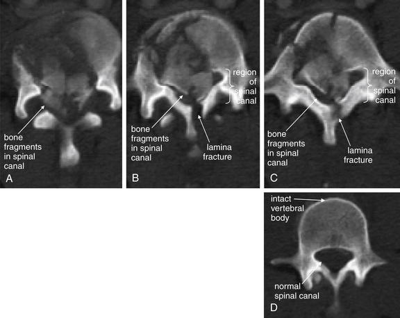
Figure 3-94 Thoracolumbar spine trauma: L5 burst fracture with cord compression.
Same patient as in Figure 3-93. Axial CT views (A, cephalad portion of vertebral body, B, middle of vertebral body, C, caudad portion of vertebral body) show significant narrowing of the spinal canal at L5 due to retropulsion of fragments of the burst L5 vertebral body. D, The normal L4 vertebra for comparison.
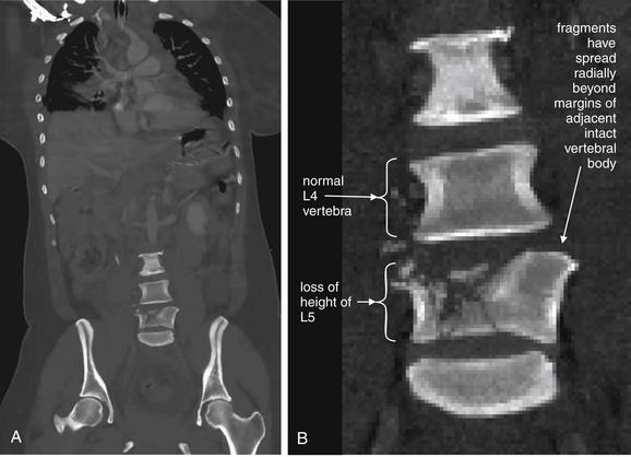
Figure 3-95 Thoracolumbar spine trauma: L5 burst fracture with cord compression.
Same patient as in Figures 3-93 and 3-94. A, Coronal CT view shows radial spread of fracture fragments and loss of height of the L5 vertebral body. B, Close-up.
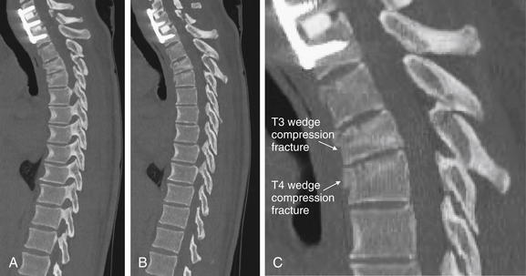
Figure 3-96 T2, T3, and T4 compression fractures.
In this patient, thoracic spine CT shows spinal fixation screws at C6, C7, and T1, which provide convenient landmarks. A to C, Sagittal CT images (C, close-up from B) reveal significant loss of height of T3, consistent with a compression-type fracture. T4 also has loss of height and evidence of an anterior wedge compression fracture. T4 nicely demonstrates the “wedge” shape typical of flexion injuries of the thoracic and lumbar spine, with the anterior height being significantly less than the posterior height. T3, in comparison, has more uniform loss of height anteriorly and posteriorly. Compression fractures often lead to radial spread of fracture fragments, and retropulsion of fragments into the spinal canal can occur, leading to spinal cord injury. The spinal canal in this patient is preserved, with no retropulsion of fracture fragments.
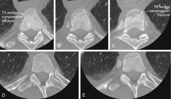
Figure 3-97 T2, T3, and T4 compression fractures.
Same patient as in Figure 3-96. On these sequential axial CT images, the extent of comminution of the fractures becomes more apparent. The T3 vertebral body is seen with comminuted fragments of the anterior vertebral body.
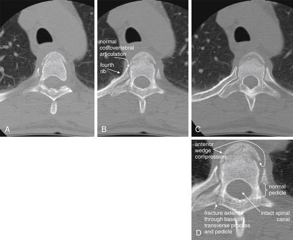
Figure 3-98 T4 wedge compression fracture.
Same patient as in Figures 3-96 and 3-97. This wedge compression fracture of T4 extends through the right pedicle and base of the transverse process, but the spinal canal is not compromised. A to C, Sequential axial CT images. D, Close-up from B.
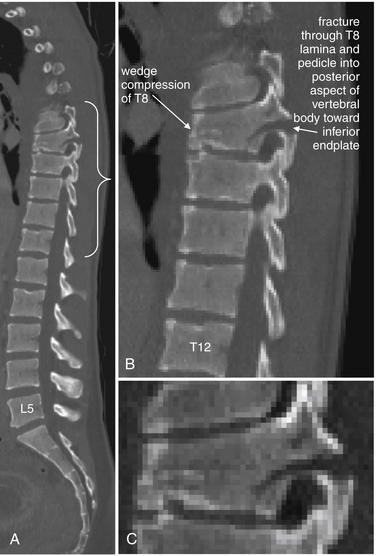
Figure 3-99 Thoracolumbar spine trauma: Chance fracture.
A, Sagittal computed tomography image. B, C, Close-ups from A.
A Chance fracture is a flexion injury, usually of the lower thoracic or upper lumbar spine. Unlike simple compression fractures, a Chance fracture involves fractures through the anterior, middle, and posterior columns of the spine. With lumbar Chance fractures, intraabdominal injuries are commonly found. A common mechanism is hyperflexion in a patient wearing a lap belt without a shoulder harness in a motor vehicle collision.
This patient has a multilevel thoracic spine flexion injury, with wedge compression fractures of T7 and T8, as well as a fracture of T10. The T8 injury follows the Chance pattern, with a comminuted fracture through the pars, lamina, and spinous process and extending through the vertebral body, with an obliquely oriented fracture through the posterior third of the middle column extending to the inferior endplate. The posterior elements are splayed with 6 mm of craniocaudal distraction. This results in focal kyphosis at T8 and approximately 33% height loss of the anterior vertebral body.
This fracture is explored in more detail in Figures 3-100 and 3-101.
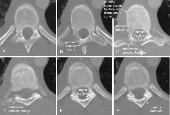
Figure 3-100 Thoracolumbar spine trauma: T8 Chance fracture.
Same patient as Figure 3-99. Axial computed tomography (CT) reconstructions of the spine (A to F), performed from a dataset from CT of the chest, abdomen, and pelvis. The T8 vertebra shows a Chance fracture pattern, with injuries to the vertebral body including the lamina, pars interarticularis (a region at the junction of the pedicle and lamina), and vertebral body. The anterior body of T8 shows compression fracture findings.
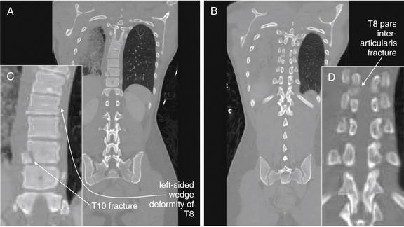
Figure 3-101 Thoracolumbar spine trauma: T8 Chance fracture.
Same patient as Figures 3-99 and 3-100. These coronal reconstructions were created from the dataset from the computed tomography (CT) of the chest, abdomen, and pelvis performed for evaluation of visceral injury in this patient. They reveal a T8 Chance fracture, as well as injuries of T7 and T10. T8 and T7 have not only anterior wedge compression (seen best on the sagittal reconstructions in Figure 3-99) but also left-sided compression, creating a scoliosis toward the patient’s left side. Spinal fractures often have complex patterns that do not strictly adhere to a single textbook description. A, Coronal view through the mid portion of the thoracic vertebral bodies. B, A more posterior coronal plane than A, showing the pars interarticularis. C and D, Close-ups from A and B, respectively.
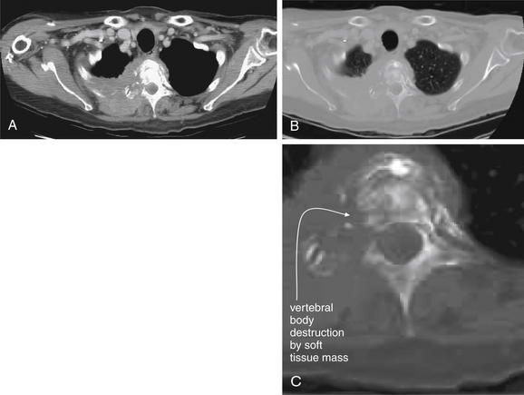
Figure 3-102 Thoracic spine metastases with cord compression.
CT with IV contrast was performed due to concern for malignancy. In comparison, dedicated spinal CT for evaluation of trauma can be performed without IV contrast. In practice today, multisystem trauma patients usually have spinal CT images reconstructed from IV contrast enhanced CT datasets of the chest, abdomen and pelvis. IV contrast in that scenario is used to evaluate solid organ and vascular injuries, not spinal injuries. This patient has a right lung mass lesion that has now invaded the T2 thoracic vertebral body. The mass has eroded the vertebral body and extends posteriorly into the paravertebral musculature. The images show the same slice on soft tissue (A) and bone windows (B). A close-up shows erosion of the right pedicle of the vertebral body (C).
Magnetic resonance imaging (MRI) demonstrates this lesion in greater detail in Figure 3-103.
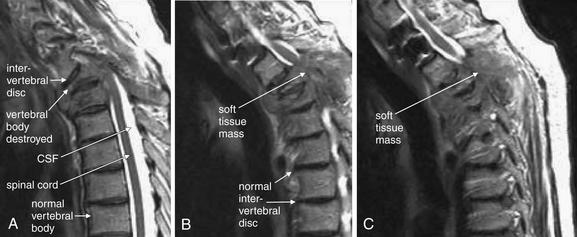
Figure 3-103 Thoracic spine metastases with cord compression.
Same patient as in Figure 3-102. The intervertebral discs show abnormal alignment because of collapse of the vertebral body. A to C, The sagittal T2-weighted images (not to be confused with the T2 vertebral body) show a lesion obliterating the cerebrospinal fluid (CSF) space surrounding the spinal cord. With T2-weighted magnetic resonance imaging (MRI), fluid appears white and fat appears darker. The spinal cord appears gray due to its myelin (fat) content. The vertebral bodies are visible due to lipid-rich marrow. The bone of the vertebral bodies is black due to a lack of resonating protons to provide a radio signal. Computed tomography (CT) is generally better than MRI for evaluation of calcified bony pathology.
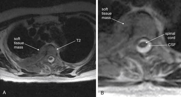
Figure 3-104 Thoracic spine metastasis with cord compression.
A, In this T2-weighted axial magnetic resonance image from the same patient as Figures 3-102 and 3-103, a soft-tissue mass is seen involving the T2 vertebral body. B, Close-up. The spinal cord is visible, surrounded by cerebrospinal fluid (CSF). The cord is not impinged upon in this image.
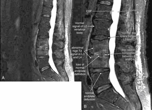
Figure 3-105 Osteomyelitis and discitis of L3 and L4.
A, T2-weighted fast spin–echo magnetic resonance imaging without contrast demonstrates typical findings of vertebral osteomyelitis and discitis. B, Close-up. The inferior endplate of L3 and the superior endplate of L4 are abnormal and ill-defined. The L3 and L4 vertebral bodies show a high T2 signal, indicating an abnormally high fluid content. In comparison, L2 shows a normal marrow signal and appears dark gray due to a normal fat signal. CSF, cerebrospinal fluid.
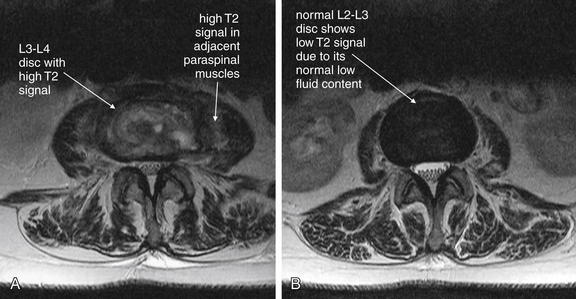
Figure 3-106 Discitis of L3 and L4.
Same patient as in Figure 3-105. T2-weighted fast spin–echo magnetic resonance imaging without contrast demonstrates typical findings of vertebral discitis. A, The L3-4 disc is shown and has a high T2 signal, indicating elevated fluid content consistent with an inflammatory process. B, The normal L2-3 disc in the same patient is shown, with its normal dark appearance (a low T2 signal) due to low fluid content. A, B, A high T2 signal is seen in the paraspinal muscles, suggesting inflammation.
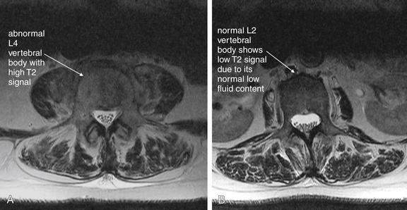
Figure 3-107 Osteomyelitis of L3 and L4.
Same patient as in Figures 3-105 and 3-106. T2-weighted fast spin–echo magnetic resonance imaging without contrast demonstrates typical findings of vertebral osteomyelitis. A, The L4 vertebral body is shown and has a high T2 signal, indicating elevated fluid content consistent with an inflammatory process. B, The normal L2 vertebral body in the same patient is shown, with its normal dark appearance (a low T2 signal) due to low fluid content. A, B, A high T2 signal is seen in the paraspinal muscles, suggesting inflammation. Compare Figure 3-107B and Figure 3-106B. Normal intervertebral discs are darker in appearance than normal vertebral bodies on this MRI sequence.
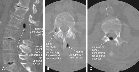
Figure 3-108 Spinal epidural abscess.
This 67-year-old female presented with delirium and fever. Three months prior, she had undergone lumbar laminectomy, and her wound had been treated with a wound VAC dressing. Magnetic resonance imaging was not initially available, so noncontrast computed tomography (CT) was performed. Noncontrast CT is excellent at delineating air, which appears black on bone windows.
A, The midsagittal view demonstrates air (black) in the spinal canal at the L2 and L3 levels. On the axial views (B, C), air is visible in the spinal canal, in paraspinal soft tissues, and within the vertebral body. These findings are concerning for a paraspinal infection that has developed into an epidural abscess with vertebral osteomyelitis. Compare with the MRI in Figure 3-109.
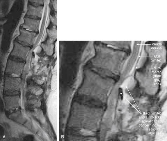
Figure 3-109 Spinal epidural abscess.
Same patient as in Figure 3-108, in whom noncontrast computed tomography showed air in the spinal canal, concerning for epidural abscess. Magnetic resonance imaging (MRI) of the lumbar spine without contrast was performed, as the patient was in acute renal failure.
A, This T2-weighted sagittal MR image provides useful information even without gadolinium contrast. B, Close-up.
On T2-weighted MRI sequences, fluid including cerebrospinal fluid appears white. Fat-containing tissues such as bone marrow and the spinal cord or cauda equina appear dark gray. Calcified bone appears nearly black due to an absence of resonating protons. Air appears completely black for the same reason.
The midline sagittal image shows the cauda equina to be impinged upon by an epidural fluid collection containing air—an epidural abscess. The dura mater is visible as a thin, dark gray line parallel to the spinal cord. It is indented in the region of the epidural abscess. Compare with the axial MRI images in Figure 3-110.
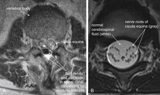
Figure 3-110 Spinal epidural abscess.
A, This axial image is taken at the same level as the air-fluid collection shown in the last figure. The air–fluid collection comprising the epidural abscess is seen posterior to the thecal sac (dura mater), which contains small, dark-gray circles representing a cross-section through the nerve roots of the cauda equina. These nerve roots are surrounded by white cerebrospinal fluid within the thecal sac. B, In another patient, the nerve roots of the cauda equina are more widely separated and are seen as discrete bundles with circular axial cross-sections.
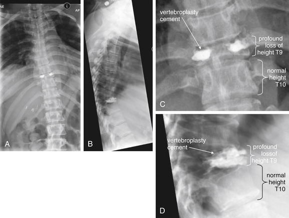
Figure 3-111 Vertebral tuberculosis (Pott’s disease).
A, Anterior–posterior x-ray. B, Lateral x-ray. C, D, Close-ups from A and B, respectively.
This patient with known tuberculosis and medication noncompliance presented with worsening back pain and lower extremity weakness. Plain x-rays show extreme loss of height of the T9 vertebral body. The high-density material is cement from an earlier vertebroplasty intended to arrest loss of height of the vertebral body. Cultures from the vertebral body confirmed mycobacterium tuberculosis. Compare with the CT and MR images in Figures 3-112 through 3-116.
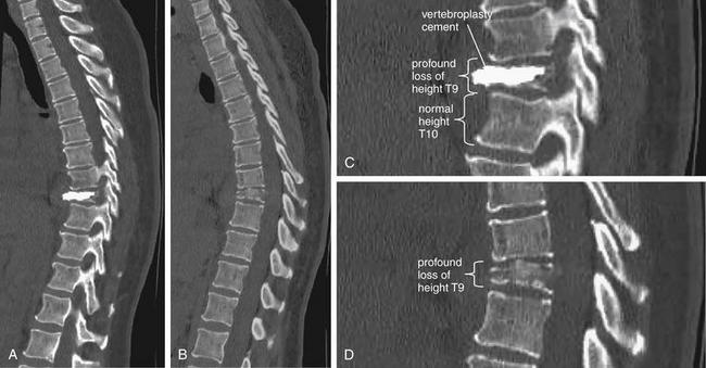
Figure 3-112 Vertebral tuberculosis (Pott’s disease).
Same patient as in Figure 3-111. Sagittal computed tomography reconstructions show extreme loss of height of the T9 vertebral body as a result of vertebral tuberculosis infection. Compression of the T9 body has resulted in kyphosis at this level. The high-density material is vertebroplasty cement from a prior procedure. A, A parasagittal section slightly to the right of midline. B, A more midline sagittal section. C, D, Close-ups from A and B, respectively.
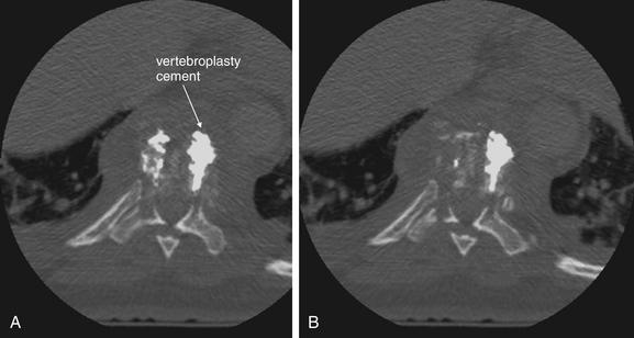
Figure 3-113 Vertebral tuberculosis (Pott’s disease).
Same patient as in Figures 3-111 and 3-112. Two axial computed tomography reconstructions (A, B) show nearly complete erosion of the T9 vertebral body as a result of vertebral tuberculosis infection. The high-density material is vertebroplasty cement from a prior procedure. Residual bone shows a moth-eaten appearance.
Figure 3-114 Vertebral tuberculosis (Pott’s disease).
Same patient as in Figures 3-111 through 3-113. Two coronal computed tomography reconstructions (A, B) show nearly complete erosion of the T9 vertebral body as a result of vertebral tuberculosis infection. The high-density material is vertebroplasty cement from a prior procedure. Residual bone shows a moth-eaten appearance. C, D, Close-ups from A and B, respectively.
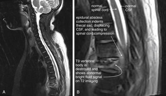
Figure 3-115 Vertebral tuberculosis (Pott’s disease) with epidural abscess.
A, Same patient as in Figures 3-111 through 3-114. Sagittal T2-weighted magnetic resonance reconstructions show nearly complete erosion of the T9 vertebral body as a result of vertebral tuberculosis infection. B, Close-up. The spinal cord is compressed from an epidural fluid collection. CSF, Cerebrospinal fluid.
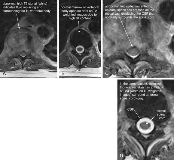
Figure 3-116 Vertebral tuberculosis (Pott’s disease) with epidural abscess.
Same patient as in Figures 3-111 through 3-115. A, Axial T2-weighted magnetic resonance (MR) images show nearly complete erosion of the T9 vertebral body as a result of vertebral tuberculosis infection. The region normally occupied by the T9 vertebral body shows a high T2 signal (white), indicating the presence of abnormal fluid (which appears white on T2-weighted MRI). The cerebrospinal fluid (CSF) that normally surrounds the spinal cord at this level has been displaced. B, A normal adjacent vertebral body and spinal cord from the same patient for comparison. C, D, Close-ups from A and B, respectively.
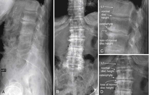
Figure 3-117 Degenerative joint disease and lumbar disc herniation.
This patient has extensive degenerative joint disease of the lumbar spine. Note the normal spacing between the L1 and the L2 vertebral bodies and the loss of normal disc height at the L2-3, L3-4, and L4-5 levels. A, Lateral x-ray. B, Anterior–posterior x-ray. C, D, Close-ups from A and B, respectively. Compare with the MRI from the same patient in Figure 3-118 through 120.
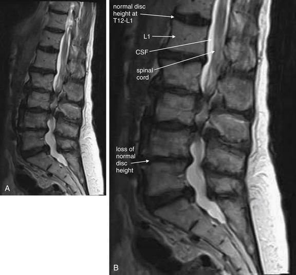
Figure 3-118 Degenerative joint disease and lumbar disc herniation: Magnetic resonance without contrast, T2-weighted image.
Same patient in Figure 3-117. A, Sagittal reconstruction. B, Close-up. This patient has extensive degenerative joint disease of the lumbar spine. At the T12-L1 level, note the normal disc space. The spinal canal is patent, with cerebrospinal fluid (CSF) (white) surrounding the cord (gray). At the L2-3 level, the intervertebral disc is compressed and indents the thecal sac into the spinal canal, displacing the normal rim of CSF and resulting in severe spinal stenosis.
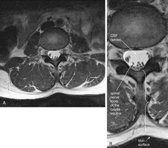
Figure 3-119 Normal cauda equina.
Same patient in Figures 3-117 and 118. A, This axial T2-weighted magnetic resonance image is taken through the L3-4 region. It illustrates that the spinal cord has given way to the cauda equina, with individual nerve roots visible in cross section (black circles). B, Close-up.
Incidentally, the distance from the skin surface to the thecal sac (cerebrospinal fluid space) is 50 mm, so lumbar puncture at this level would be feasible.

Figure 3-120 Disk herniation resulting in cauda equina compression: Magnetic resonance imaging (MRI) lumbar spine without contrast.
Same patient as Figure 3-119, but at a lower spinal level. A, This axial T2-weighted MRI image is taken through the L4-5 disc region. A paracentral disc herniation is compressing the thecal sac on the patient’s left, narrowing the left neural foramen. The spinal cord has already given way to the nerve roots of the cauda equina at this level. B, A normal section above the level of the disc herniation for comparison—note the triangular shape of the normal thecal sac at this level. C, Close-up from A.
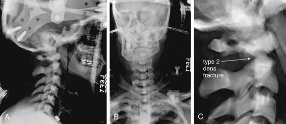
Figure 3-121 Osteopetrosis with type II dens fracture.
A, Lateral x-ray. B, Anterior–posterior x-ray. C, Close-up from A.
Osteopetrosis is a pathologic condition of increased bone density but high predisposition to fracture. Note this patient’s high bone density, which is not simply a function of the exposure. This patient has a type II dens fracture. Compare with the CT in Figure 3-122.
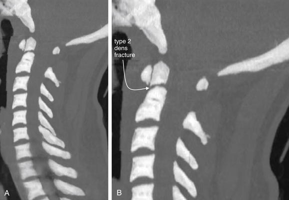
Figure 3-122 Osteopetrosis with type II dens fracture.
Same patient as in Figure 3-121. A, Midsagittal computed tomography (CT) slice. B, Close-up. Note this patient’s high bone density. This is not simply a function of the window level, which is set to “bone,” as with most of the other CT images in this chapter. This patient has a type II dens fracture, with slight craniocaudal distraction of the fracture fragments. The dens is not retropulsed into the spinal canal.
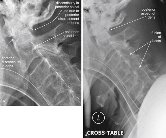
Figure 3-123 Ankylosing spondylitis with type II dens fracture.
A, This lateral x-ray (B, broader view) shows typical features of ankylosing spondylitis with fusion of facet joints, straightening of the cervical spine, and diffuse osteopenia. A dens fracture is present with retropulsion of the dens into the spinal canal. The posterior longitudinal ligament line would intersect the dens rather than passing posterior to it. The patient’s computed tomography scan is explored in Figures 3-124 through 3-126.
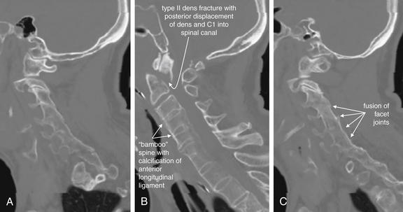
Figure 3-124 Ankylosing spondylitis with type II dens fracture.
Same patient as in Figure 3-123. These sagittal computed tomography reconstructions show fusion of facets bilaterally (A, right, and C, left) and “bamboo” spine in the midline sagittal section (B). The spine shows diffuse osteopenia that is also typical of ankylosing spondylitis. The cervical spine is straightened, not due to the cervical collar but due to fusion of vertebrae. Worse still, the patient has a type II dens fracture. The dens and C1 vertebra are bound together by the transverse ligament and have moved posteriorly as a unit, intruding into the spinal canal and narrowing it by more than 50%.
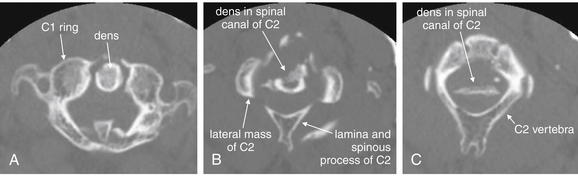
Figure 3-125 Ankylosing spondylitis with type II dens fracture.
Same patient as in Figures 3-123 and 3-124. These axial computed tomography views may appear confusing at first. In the most cephalad slice (A), the dens is normally positioned relative to the ring of C1. This is because the dens has remained attached to the anterior ring of C1 by the transverse ligament. However, a few slices caudad (B), a cross section through the dens shows it to be in the center of the spinal canal of the C2 vertebra, not positioned anteriorly. Further caudad (C), the bottom of the dens fragment is still seen in the spinal canal. Bone in the spinal canal threatens the spinal cord (as seen in magnetic resonance imaging in Figure 3-127).
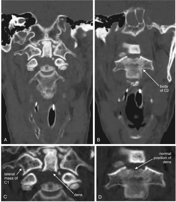
Figure 3-126 Ankylosing spondylitis with type II dens fracture.
Same patient as in Figures 3-123 through 3-125. This badly displaced type II dens fracture is depicted in coronal CT views. Because the dens has been displaced significantly from the body of C2, the two are not seen in the same coronal view. These two views are separated by 10 mm in an anterior–posterior direction. The dens remains in its normal position relative to C1. C, D, Close-ups from A and B, respectively.
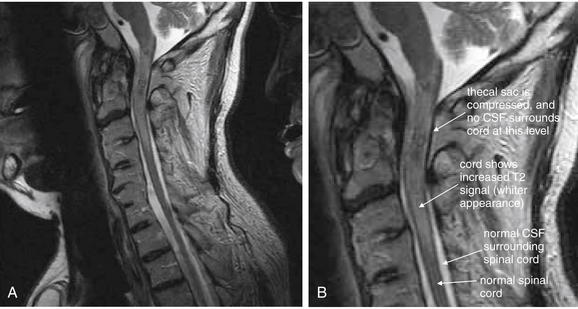
Figure 3-127 Ankylosing spondylitis with type II dens fracture: Cervical magnetic resonance imaging (MRI) without contrast.
Same patient as in Figures 3-123 through 3-126. A, In this T2-weighted midsagittal MRI, a dens fracture with retropulsion of the dens into the spinal canal has compressed the spinal cord. B, Close-up.
Several features are evident. First, the thecal sac has been indented, displacing the rim of cerebrospinal fluid (CSF) that normally surrounds the spinal cord. In addition, the spinal cord shows an increased T2 signal, indicating traumatic edema of the cord. Compare this abnormal, whiter appearance of the cord with the normal, darker gray appearance of the cord above and below the level of injury.
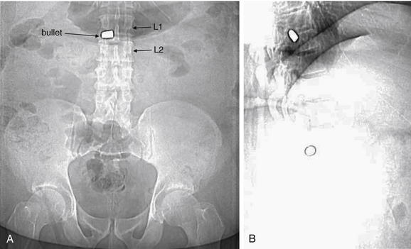
Figure 3-128 Penetrating spinal trauma: Bullet in spinal canal.
Scout computed tomography (CT) images show a bullet overlying the L1-2 disc space on both frontal (A) and lateral (B) reconstructions. Multiplanar CT reconstructions of the spine were performed (Figures 3-129 through 3-131).
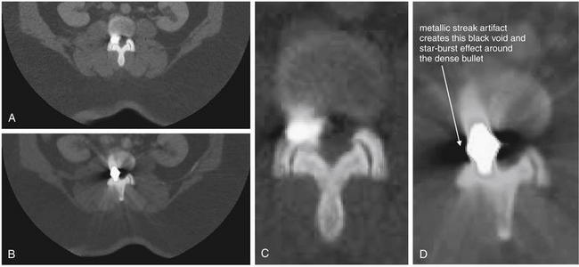
Figure 3-129 Penetrating spinal trauma: Bullet in spinal canal.
Same patient as in Figure 3-128. A, B, Axial computed tomography (CT) slices. C, D, Close-ups from A and B, respectively.
Axial CT reconstructions show a bullet located in the right lateral aspect of the disc space, neural foramina, and central canal at the L1-2 level. Metallic streak artifact limits detection of fractures in this CT. The patient is also morbidly obese, limiting the image quality.
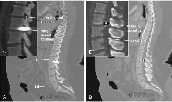
Figure 3-130 Penetrating spinal trauma: Bullet in spinal canal.
Same patient as in Figures 3-128 and 3-129. A, B, Sagittal computed tomography (CT) slices. C, D, Close-ups from A and B, respectively.
Sagittal reconstructions show the bullet in the right neural foramen and central spinal canal. Streak artifact makes it impossible to discern the exact margins of the bullet.
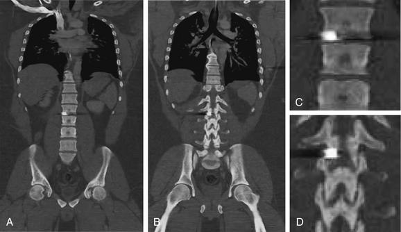
Figure 3-131 Penetrating spinal trauma: Bullet in spinal canal.
Same patient as in Figures 3-128 through 3-130. These coronal CT reconstructions show the bullet to lie just inferior to L1, in the L1-2 interspace. Again, streak artifact makes finding the bullet margins and recognizing adjacent fractures impossible. A, Coronal view through the midportion of the affected vertebral bodies. B, A more posterior coronal plane shows posterior facets. C and D, Close-ups from A and B, respectively.
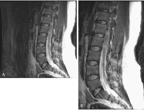
Figure 3-132 Epidural hematoma after lumbar puncture with motion artifact.
A, T2-weighted sagittal image. B, Close-up.
This patient underwent magnetic resonance imaging (MRI) to assess for epidural hematoma after a lumbar puncture. The patient had difficulty remaining still during the exam, which lasted approximately 45 minutes. As a result, significant motion artifact limits the diagnostic quality of the MRI.
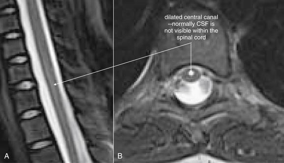
A, Sagittal T2-weighted magnetic resonance image. B, Axial T2-weighted image.
A syrinx occurs when spinal fluid dissects within the spinal cord. A risk factor is Chiari malformation, as this can increase the pressure of cerebrospinal fluid (CSF) within the spinal cord. In this 10-year-old female presenting with leg numbness, a dilated cervical central canal gave way to a small syrinx at the T7 level.
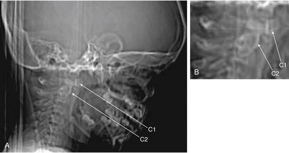
Figure 3-134 Pseudosubluxation.
A, Lateral CT scout image. B, Close-up.
This 3-year-old male presented with torticollis and was suspected of having a retropharyngeal abscess. The computed tomography (CT) was normal, but it demonstrates some important pediatric findings that can be mistaken for pathology by an inexperienced reader, especially one more accustomed to adult CT. The scout CT shows pseudosubluxation of C1 on C2.
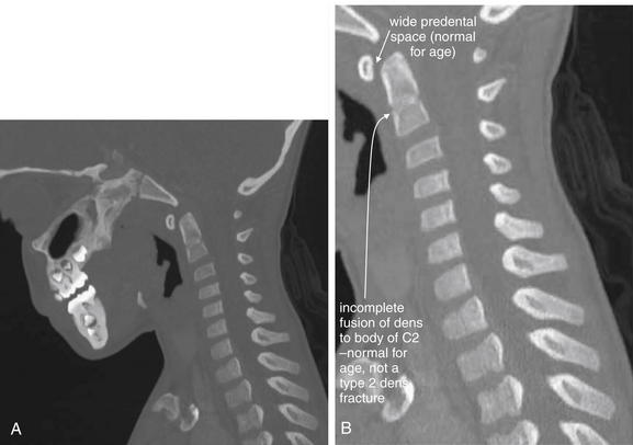
Figure 3-135 Pseudosubluxation.
Same patient as in Figure 3-134. A, Sagittal computed tomography (CT) slice. B, Close-up.
This 3-year-old male wmistaken for pathology by an inexperienced reader. The midsagittal view shows a slightly widened predental space (normal for age) and incomplete fusion of the dens to the body of C2 (normal for age), which should not be confused with type II dens fracture.
Who Needs Thoracic and Lumbar Imaging? Is There a Clinical Decision Rule for These Regions?
Unlike the case with injuries to the cervical spine, no single large study has produced a well-validated CDR for imaging of the thoracic and lumbar spine that both detects all injuries and avoids unnecessary imaging. First, we lay out the best-evidence indications for imaging the thoracic and lumbar spine. Then, we examine the evidence behind these recommendations.
The ACR recommends thoracic and lumbar spine imaging for any of the following after major blunt trauma1,62-63:
Notice the similarity to NEXUS—the items are identical, with the addition of local examination findings and coexisting cervical spine fracture.
Several studies have contributed to these recommendations. A prospective study of 2404 patients evaluated seven high-risk criteria as a screening tool for identification of patients at risk for thoracolumbar injury.64 The criteria included the five NEXUS criteria, with back pain and “severe mechanism of injury” as additional potential predictors of thoracolumbar fracture (Box 3-12). The authors also reported the predictive value of the presence of a cervical spine injury for detecting other spinal injuries, although this is not necessarily a data point available to the emergency physician at the initial assessment when many diagnostic imaging plans are formulated. The study identified 152 patients with spinal injuries. Use of the first six high-risk criteria resulted in 100% sensitivity (95% CI = 98%-100%) and 100% negative predictive value (95% CI = 97%-100%). Unfortunately, this rule is quite nonspecific (3.9%, 95% CI = 3.1%-4.8%) and has poor positive predictive value (6.6%, 95% CI = 97%-100%). As a result, application of this rule, while detecting all injuries, would result in imaging of virtually all major blunt trauma patients. Addition of “severe mechanism of injury” did not improve sensitivity (already 100%) but worsened specificity to only 2% (95% CI = 1.5%-2.7%). Of note, each of the first six high-risk predictors except intoxication was present as the sole predictor of injury in some cases—meaning that a simpler rule with fewer elements would miss injuries. Eliminating intoxication as a criterion would slightly improve specificity to 4.6% (95% CI = 3.7%-5.5%). The authors did calculate the sensitivity and specificity
Box 3-12 High-Risk Criteria for Thoracolumbar Injury∗
∗ Studies suggest that the presence of even a single criterion indicates imaging. The first 6 criteria above are 100% sensitive, without inclusion of severe mechanism.
of other combinations of the high-risk elements, but minimal improvements in specificity were achieved at the price of loss of sensitivity. The presence of a cervical spine fracture was noted to have a stronger predictive value than any of the other risk factors assessed, increasing the risk of thoracolumbar injury by threefold when present. The authors recommended adding this to a CDR to enhance predictive value.
The same research group went on to delineate the types of distracting injuries most associated with thoracolumbar fractures. When “painful distracting injury” was the only high-risk predictor present, bony fractures were associated with thoracolumbar injury, while soft-tissue contusions, lacerations, head injuries, abrasions, visceral injuries, dental injuries, burns, ligamentous injuries, amputations, and compartment syndrome were not. Although the investigators suggest that this data can be used to refine the screening definition of “painful distracting injury,” only 13 thoracolumbar injuries were found in this group, limiting the ability to consider injury subtypes.65
Hsu et al.62 conducted a retrospective chart review of 200 patients and reported the sensitivity of various physical exam findings for thoracolumbar fracture. In this study, a midline step-off was found to be poorly sensitive (13.8%) but highly specific (100%). Back bruising was only 6.9% sensitive but 98.6% specific. Back pain or midline tenderness had a sensitivity of 62.1% and a specificity of 91.5%. An abnormal neurologic examination was 41.4% sensitive and 95.8% specific.62 This study is limited by its small size, resulting in wide CIs. In addition, the study faces significant methodologic problems. Physical examination findings were abstracted from the emergency department chart, and it is possible that examination findings may have been present but not written in the chart, resulting in inaccurate calculations of sensitivity and specificity. However, the apparent specificity of local findings such as bruising or step-offs has led to the recommendation by professional societies that these be criteria for thoracolumbar imaging.1,63
The case is less clear for low-energy mechanisms of trauma—for example, is any imaging required in the 30-year-old patient who complains of back pain after low-speed rear-end collision but is ambulatory in the emergency department? Thoracic and lumbar injuries are less common after minor trauma mechanisms, and many patients may require no imaging. Spectrum bias in studies such as those described earlier (biased toward moderately severely injured patients) may limit the application of these rules to less significantly injured patients.
What Is the Sensitivity of X-ray and Computed Tomography for Injuries of the Thoracolumbar Spine? Which Imaging Modality Should Be Used?
Studies comparing x-ray and CT for the diagnosis of thoracolumbar fracture suffer the same methodologic flaws as those for cervical spine injury, including the lack of a uniform and independent gold standard. The use of CT as the gold standard in studies is called incorporation bias and virtually guarantees that CT will appear to be the superior test. That said, CT is almost certainly far superior to x-ray for detection and characterization of fractures. Rhee et al.66 reported the missed lumbar fracture rate for abdominal and pelvic CT to be 23.1%, versus 12.7% for AP and lateral x-ray. However, these figures are based on axial images from abdominal and pelvic CT viewed on bone windows without sagittal or coronal reformatted images, using a single-slice helical scan with slice thicknesses of 5 to 10 mm. Modern protocols routinely use thinner slices and incorporate multiplanar reformations, improving recognition of malalignment and fractures that may lie in the axial plane. In addition, this study had no uniform diagnostic standard, making the results uncertain. Multiple other studies have shown excellent test performance characteristics for images obtained from abdominal and pelvic CT, reformatted in the sagittal and coronal planes.67-77 Some reports focused on use of axial CT images, supplemented by AP and lateral scout CT images. These were found to have sensitivity of 92% to 100% and specificity of 100% compared with AP and lateral lumbar spine x-ray.68,78 A prospective study compared axial images from the chest–abdomen–pelvis CT with AP and lateral x-rays. The gold standard for the study was either separately acquired, dedicated thin-cut spine CT (1- to 2-mm cuts) or clinical exam of the patient once stable and awake. Axial images from the chest–abdomen–pelvis CT were found to have a sensitivity of 97% (95% CI = 86%-100%), with a specificity of 99% (95% CI = 96%-100%). In comparison, x-ray had a sensitivity of only 58% (95% CI = 41%-75%) and a specificity of 93% (95% CI = 89%-97%). From a methodology standpoint, this study suffers from its inconsistent gold standard (also called verification or workup bias) and a lack of blinding, as radiologists were aware of the results of other imaging studies when rendering their interpretation of the CT and x-rays.69
Sheridan et al.75 prospectively investigated reformatted sagittal and coronal images obtained from chest–abdomen–pelvis CT–the technique used in most trauma centers today and advocated by the ACR. They reported 97% sensitivity and 95% specificity of CT for lumbar fractures, compared with 62% sensitivity and 86% specificity of x-ray. This study is limited by the lack of a uniform diagnostic standard; the final discharge diagnosis was considered to be correct, though not all patients underwent the same final workup. In addition, although the authors report that the CT and lumbar spine x-rays were generally read blinded, they admit that some were read by the same radiologist without blinding. This practice likely artificially inflates the sensitivity of x-ray, because findings on CT might lead to recognition of additional fractures. Theoretically, x-ray findings might also have led to recognition of CT abnormalities.75
Wintermark et al.77 performed a prospective double-blinded study of 100 consecutive trauma patients undergoing both thoracolumbar x-ray and CT of the chest, abdomen, and pelvis with coronal and sagittal reformats. They reported the mean sensitivity for unstable fractures to be 97% for CT (95% CI = 85.5%-99.9%) and the mean sensitivity to be 33.3% for x-ray (95% CI = 21.7%-46.7%). In addition, the K value for interobserver agreement was 0.951 for CT, indicating near-perfect agreement of different interpreting radiologists, compared with poor agreement (K = 0.368) for x-ray.77 For all fractures, including fractures predicted to be stable, agreement (K = 0.787), and sensitivity (78.1%) of CT were less perfect although arguably, stable fractures are less important to patient outcome. CT nonetheless was superior to x-ray in this category as well (sensitivity = 32%, K = 0.661). This study was well done, with its primary weakness being a mixed gold standard based on additional imaging, orthopedic interventions, and final discharge diagnosis or autopsy report.77
Who Needs Magnetic Resonance Imaging of the Thoracic and Lumbar Spine?
The ACR does not recommend MRI for evaluation of ligamentous injuries of the thoracolumbar spine when CT is normal. Unlike the case for the cervical spine, in which some controversy exists and MRI is commonly performed for evaluation of ligamentous injuries even in the presence of a normal CT scan (see earlier discussion), ligamentous injuries of the thoracolumbar spine almost never occur in the absence of CT findings. MRI is recommended solely for patients with neurologic deficits localizing to the thoracolumbar spine.1
Which Is Faster, X-ray or CT of the Thoracic and Lumbar Spine?
Wintermark et al.77 reported thoracolumbar x-ray required a median of 23 minutes, while CT of the chest, abdomen, and pelvis required a median of 40 minutes, of which 7 minutes was required for postprocessing of images. In patients undergoing CT of the chest, abdomen, and pelvis for evaluation of other traumatic injuries, CT reformations are clearly the more rapid means of assessing the thoracolumbar spine.
What Is the Cost of X-ray and CT of the Thoracic and Lumbar Spine?
Wintermark et al.77 reported costs of $145 per patient for x-ray and $880 for CT. They using reformats of the spine derived from chest–abdomen–pelvis CT. They discounted the cost of the CT spinal reformats, stating that these added nothing to the cost of CT. However, in some cases, additional fees for postprocessing may be charged to the patient. If the patient does not require chest, abdomen, and pelvis CT for evaluation of other injuries and dedicated spine CT is performed, CT is more costly, accounting for direct costs alone. Given the higher sensitivity of CT, economic models incorporating the cost of missed injuries would likely favor CT.
What Is the Radiation Exposure of Thoracolumbar X-ray and CT?
Wintermark et al.77 reported mean effective radiation dose from thoracolumbar x-ray to be 6.36 mSv, compared with 19.42 mSv for CT reformations of the spine derived from chest–abdomen–pelvis CT. They note that the reformations do not require any additional imaging or radiation exposure, compared with CT of the chest, abdomen, and pelvis alone. Consequently, if the patient requires CT of these regions for evaluation of other traumatic injuries, use of CT reformations allows a reduction of 6.36 mSv (by eliminating the additional radiation exposure from x-ray), nearly 25% of the entire dose required to perform both abdominal CT and x-rays of the spine.77 However, if the patient does not require visceral CT of the chest, abdomen, and pelvis for trauma evaluation, dedicated CT of the spine would result in a significant increase in radiation exposure compared with x-ray.
Should Minor Trauma Patients Undergo Lumbar CT or X-ray?
Most of the published studies comparing CT and x-ray involve patients with high trauma mechanisms and significant associated injuries. In these patients, CT is more sensitive, faster, more cost effective, and more radiation efficient than x-ray, because CT images of the spine can be reformatted from CT acquired for evaluation of other injuries to the chest, abdomen, and pelvis. Less clear is the best workup for patients with more minor trauma mechanisms. Some of these patients likely do not require CT evaluation of the chest, abdomen, and pelvis. For example, many blunt trauma patients with relatively low-energy mechanisms are probably not at risk for aortic trauma, a high-energy injury that is the strongest indication for chest CT. Despite this, CT is often ordered in this circumstance because of its value in imaging the thoracolumbar spine. Probably, patients with a low pretest probability of both major torso organ injury and thoracolumbar spinal injury should undergo thoracolumbar x-ray instead of CT. The ACR rates x-ray as less appropriate (three on a nine-point scale) than CT (nine on the same scale) for “blunt trauma meeting criteria for thoracic or lumbar imaging.”1 However, given the lower incidence of thoracolumbar injuries in very-low-energy trauma, such as falls from standing, CT appears inappropriate given its cost and radiation exposure.1 If evaluation of the chest or abdomen is anticipated, it is clearly more efficient to order chest–abdomen–pelvis CT with spine reformats as the initial imaging study, rather than potentially subjecting the patient to two CTs: a dedicated spine CT followed later by CT of the chest, abdomen, and pelvis.
Which Patients Require Thoracolumbar Imaging for Low Back Pain? Are So-Called Red Flags Useful?
Red flags, or clinical features suggesting serious causes of back pain, are frequently cited in medical texts as indications for imaging. A number of national guidelines have been published with recommendations for imaging only when red flags are present. Are these based on expert opinion or on high-quality research? A systematic review of Medline, the Cumulative Index to Nursing and Allied Health Literature, and Embase found 12 studies meeting sound methodologic quality criteria and investigating 51 clinical “red flags.” Five clinical features were identified as useful in raising or lowering the probability of vertebral fracture (Table 3-5).79 Likelihood ratios for each finding are presented. A likelihood ratio represents a multiplier used to modify pretest probability of disease, based on a “test,” which in this case may be a clinical exam maneuver or historical feature. Of note, a positive likelihood ratio greater than or equal to 10, or a negative likelihood ratio less than or equal to 0.1, is generally accepted as having substantial value in clinical practice. Less extreme likelihood ratio values do not alter pretest probability to an extent that is likely to assist in clinical decisions. Even the five “best” red flags identified in this review generally fall short of these criteria. The authors intentionally set a lower threshold, choosing features for which the upper 95% CI of the likelihood ratio was substantially below 1.0 or for which the lower 95% CI of the likelihood ratio was substantially above 1.0. This is because a likelihood ratio approaching 1.0 results in no mathematical change in pretest probability.
TABLE 3-5 Red Flags for Lumbar Vertebral Fracture
| Clinical Feature | Positive Likelihood Ratio | Negative Likelihood Ratio |
|---|---|---|
| Age > 50 years | 2.2 | 0.34 |
| Female gender | 2.3 | 0.67 |
| History of major trauma | 12.8 | 0.37 |
| Pain and tenderness | 6.7 | 0.44 |
| Painful distracting injury | 1.7 | 0.78 |
Summary
Imaging of the spine is often indicated following trauma or for evaluation of neurologic complaints. CDRs exist to limit imaging in low-risk trauma patients. X-ray may be appropriate for screening of low-risk patients who require imaging, but the ACR recommends CT due to its higher sensitivity. The high costs and radiation exposures associated with CT make application of CDRs particularly important MRI is necessary when serious concern exists for spinal cord pathology.
1. American College of Radiology: ACR Appropriateness Criteria. Suspected Spine Trauma 2009. Available at: http://www.acr.org/SecondaryMainMenuCategories/quality_safety/app_criteria/pdf/ExpertPanelonMusculoskeletalImaging/SuspectedCervicalSpineTraumaDoc22.aspx. Accessed 3-19-2011.
2. Grossman M.D., Reilly P.M., Gillett T., et al. National survey of the incidence of cervical spine injury and approach to cervical spine clearance in U.S. trauma centers. J Trauma. 1999;47(4):684-690.
3. Goldberg W., Mueller C., Panacek E., et al. Distribution and patterns of blunt traumatic cervical spine injury. Ann Emerg Med. 2001;38(1):17-21.
4. Hoffman J.R., Wolfson A.B., Todd K., et al. Selective cervical spine radiography in blunt trauma: Methodology of the National Emergency X-Radiography Utilization Study (NEXUS). Ann Emerg Med. 1998;32(4):461-469.
5. Touger M., Gennis P., Nathanson N., et al. Validity of a decision rule to reduce cervical spine radiography in elderly patients with blunt trauma. Ann Emerg Med. 2002;40(3):287-293.
6. Diaz J.J.Jr., Gillman C., Morris J.A.Jr., et al. Are five-view plain films of the cervical spine unreliable? A prospective evaluation in blunt trauma patients with altered mental status. J Trauma. 2003;55(4):658-663. discussion 663-64
7. Stiell I.G., Wells G.A., Vandemheen K.L., et al. The Canadian C-Spine Rule for radiography in alert and stable trauma patients. JAMA. 2001;286(15):1841-1848.
7a. Ehrlich P.F., Wee C., Drongowski R., et al. Canadian C-spine rule and the national emergency X-radiography utilization low-risk criteria for C-spine radiography in young trauma patients. J Pediatr Surg. 2009;44(5):987-991.
8. Stiell I.G., Clement C.M., McKnight R.D., et al. The Canadian C-Spine Rule versus the NEXUS low-risk criteria in patients with trauma. N Engl J Med. 2003;349(26):2510-2518.
9. Viccellio P., Simon H., Pressman B.D., et al. A prospective multicenter study of cervical spine injury in children. Pediatrics. 2001;108(2):E20.
10. Holmes J.F., Akkinepalli R. Computed tomography versus plain radiography to screen for cervical spine injury: A meta-analysis. J Trauma. 2005;58(5):902-905.
11. Besman A., Kaban J., Jacobs L., et al. False-negative plain cervical spine x-rays in blunt trauma. Am Surg. 2003;69(11):1010-1014.
12. Griffen M.M., Frykberg E.R., Kerwin A.J., et al. Radiographic clearance of blunt cervical spine injury: Plain radiograph or computed tomography scan? J Trauma. 2003;55(2):222-226. discussion 226-7
13. Singh Ranger G, Crinnon JN. “Radiographic clearance of blunt cervical spine injury: Plain radiograph or computed tomography scan?” by Griffen MM, et al. J Trauma 56(2);457, 2004; author reply 457.
14. Schenarts P.J., Diaz J., Kaiser C., et al. Prospective comparison of admission computed tomographic scan and plain films of the upper cervical spine in trauma patients with altered mental status. J Trauma. 2001;51(4):663-668. discussion 668-9
15. Barba C.A., Taggert J., Morgan A.S., et al. A new cervical spine clearance protocol using computed tomography. J Trauma. 2001;51(4):652-656. discussion 656-7
16. Mower W.R., Hoffman J.R., Pollack C.V.Jr., et al. Use of plain radiography to screen for cervical spine injuries. Ann Emerg Med. 2001;38(1):1-7.
17. Pang D., Wilberger J.E.Jr. Spinal cord injury without radiographic abnormalities in children. J Neurosurg. 1982;57(1):114-129.
18. Fesmire F.M., Luten R.C. The pediatric cervical spine: Developmental anatomy and clinical aspects. J Emerg Med. 1989;7(2):133-142.
19. Osenbach R.K., Menezes A.H. Spinal cord injury without radiographic abnormality in children. Pediatr Neurosci. 1989;15(4):168-174. discussion 175
20. Pang D., Pollack I.F. Spinal cord injury without radiographic abnormality in children: The SCIWORA syndrome. J Trauma. 1989;29(5):654-664.
21. Ruge J.R., Sinson G.P., McLone D.G., et al. Pediatric spinal injury: The very young. J Neurosurg. 1988;68(1):25-30.
22. Hendey G.W., Wolfson A.B., Mower W.R., et al. Spinal cord injury without radiographic abnormality: Results of the National Emergency X-Radiography Utilization Study in blunt cervical trauma. J Trauma. 2002;53(1):1-4.
23. Patel J.C., Tepas J.J.III, Mollitt D.L., et al. Pediatric cervical spine injuries: Defining the disease. J Pediatr Surg. 2001;36(2):373-376.
24. Menaker J., Philp A., Boswell S., et al. Computed tomography alone for cervical spine clearance in the unreliable patient: Are we there yet? J Trauma. 2008;64(4):898-903. discussion 903-904
25. Stelfox H.T., Velmahos G.C., Gettings E., et al. Computed tomography for early and safe discontinuation of cervical spine immobilization in obtunded multiply injured patients. J Trauma. 2007;63(3):630-636.
26. Como J.J., Thompson M.A., Anderson J.S., et al. Is magnetic resonance imaging essential in clearing the cervical spine in obtunded patients with blunt trauma? J Trauma. 2007;63(3):544-549.
27. Tomycz N.D., Chew B.G., Chang Y.F., et al. MRI is unnecessary to clear the cervical spine in obtunded/comatose trauma patients: The four-year experience of a level I trauma center. J Trauma. 2008;64(5):1258-1263.
28. Sekula R.F.Jr., Daffner R.H., Quigley M.R., et al. Exclusion of cervical spine instability in patients with blunt trauma with normal multidetector CT (MDCT) and radiography. Br J Neurosurg. 2008;22(5):669-674.
29. Hogan G.J., Mirvis S.E., Shanmuganathan K., et al. Exclusion of unstable cervical spine injury in obtunded patients with blunt trauma: Is MR imaging needed when multidetector row CT findings are normal? Radiology. 2005;237(1):106-113.
30. Stassen N.A., Williams V.A., Gestring M.L., et al. Magnetic resonance imaging in combination with helical computed tomography provides a safe and efficient method of cervical spine clearance in the obtunded trauma patient. J Trauma. 2006;60(1):171-177.
31. Adams J.M., Cockburn M.I., Difazio L.T., et al. Spinal clearance in the difficult trauma patient: A role for screening MRI of the spine. Am Surg. 2006;72(1):101-105.
32. Cattell H.S., Filtzer D.L. Pseudosubluxation and other normal variations in the cervical spine in children: A study of one hundred and sixty children. J Bone Joint Surg Am. 1965;47(7):1295-1309.
33. Swischuk L.E. Anterior displacement of C2 in children: physiologic or pathologic. Radiology. 1977;122(3):759-763.
34. Pollack C.V.Jr., Hendey G.W., Martin D.R., et al. Use of flexion–extension radiographs of the cervical spine in blunt trauma. Ann Emerg Med. 2001;38(1):8-11.
35. Insko E.K., Gracias V.H., Gupta R., et al. Utility of flexion and extension radiographs of the cervical spine in the acute evaluation of blunt trauma. J Trauma. 2002;53(3):426-429.
36. Mirvis S.E. Fluoroscopically guided passive flexion–extension views of the cervical spine in the obtunded blunt trauma patient: A commentary. J Trauma. 2001;50(5):868-870.
37. Davis J.W., Kaups K.L., Cunningham M.A., et al. Routine evaluation of the cervical spine in head-injured patients with dynamic fluoroscopy: A reappraisal. J Trauma. 2001;50(6):1044-1047.
38. Cothren C.C., Moore E.E., Biffl W.L., et al. Cervical spine fracture patterns predictive of blunt vertebral artery injury. J Trauma. 2003;55(5):811-813.
39. Daffner R.H. Cervical radiography for trauma patients: A time-effective technique? AJR Am J Roentgenol. 2000;175(5):1309-1311.
40. Daffner R.H. Helical CT of the cervical spine for trauma patients: A time study. AJR Am J Roentgenol. 2001;177(3):677-679.
41. Richards P.J., Summerfield R., George J., et al. Major trauma & cervical clearance radiation doses & cancer induction. Injury. 2008;39(3):347-356.
42. Blackmore C.C., Ramsey S.D., Mann F.A., et al. Cervical spine screening with CT in trauma patients: A cost-effectiveness analysis. Radiology. 1999;212(1):117-125.
43. Grogan E.L., Morris J.A.Jr., Dittus R.S., et al. Cervical spine evaluation in urban trauma centers: Lowering institutional costs and complications through helical CT scan. J Am Coll Surg. 2005;200(2):160-165.
44. Stabler A., Eck J., Penning R., et al. Cervical spine: Postmortem assessment of accident injuries—Comparison of radiographic, MR imaging, anatomic, and pathologic findings. Radiology. 2001;221(2):340-346.
45. Jonsson H.Jr., Bring G., Rauschning W., et al. Hidden cervical spine injuries in traffic accident victims with skull fractures. J Spinal Disord. 1991;4(3):251-263.
46. Darouiche R.O. Spinal epidural abscess. N Engl J Med. 2006;355(19):2012-2020.
47. Williams M.F., Eisele D.W., Wyatt S.H. Neck needle foreign bodies in intravenous drug abusers. Laryngoscope. 1993;103(1 Pt 1):59-63.
48. Myers E.M., Kirkland L.S.Jr., Mickey R. The head and neck sequelae of cervical intravenous drug abuse. Laryngoscope. 1988;98(2):213-218.
49. Smith M.A., Trowers N.R., Klein R.S. Cervical osteomyelitis caused by Pseudomonas cepacia in an intravenous-drug abuser. J Clin Microbiol. 1985;21(3):445-446.
50. Sapico F.L., Montgomerie J.Z. Vertebral osteomyelitis in intravenous drug abusers: Report of three cases and review of the literature. Rev Infect Dis. 1980;2(2):196-206.
51. Darouiche R.O., Hamill R.J., Greenberg S.B., et al. Bacterial spinal epidural abscess: Review of 43 cases and literature survey. Medicine (Baltimore). 1992;71(6):369-385.
52. Ravicovitch M.A., Spallone A. Spinal epidural abscesses: Surgical and parasurgical management. Eur Neurol. 1982;21(5):347-357.
53. Jerrard D.A., Olshaker J. Simultaneous uvulitis and epiglottitis without fever or leukocytosis. Am J Emerg Med. 1996;14(6):551-552.
54. Rigamonti D., Liem L., Sampath P., et al. Spinal epidural abscess: Contemporary trends in etiology, evaluation, and management. Surg Neurol. 1999;52(2):189-196. discussion 197
55. Redekop G.J., Del Maestro R.F. Diagnosis and management of spinal epidural abscess. Can J Neurol Sci. 1992;19(2):180-187.
56. Ekbom D.C., J De Isaacson B., et al. Spinal epidural abscess after cervical pharyngoesophageal dilation. Head Neck. 2005;27(6):543-548.
57. Robertson A., Branfoot T., Barlow I.F., et al. Spinal injury patterns resulting from car and motorcycle accidents. Spine. 2002;27(24):2825-2830.
58. Dai L.Y., Yao W.F., Cui Y.M., et al. Thoracolumbar fractures in patients with multiple injuries: Diagnosis and treatment—A review of 147 cases. J Trauma. 2004;56(2):348-355.
59. Denis F. The three column spine and its significance in the classification of acute thoracolumbar spinal injuries. Spine. 1983;8(8):817-831.
60. McAfee P.C., Yuan H.A., Fredrickson B.E., et al. The value of computed tomography in thoracolumbar fractures: An analysis of one hundred consecutive cases and a new classification. J Bone Joint Surg Am. 1983;65(4):461-473.
61. Patel R.V., DeLong W.Jr., Vresilovic E.J. Evaluation and treatment of spinal injuries in the patient with polytrauma. Clin Orthop Relat Res. 2004(422):43-54.
62. Hsu J.M., Joseph T., Ellis A.M. Thoracolumbar fracture in blunt trauma patients: Guidelines for diagnosis and imaging. Injury. 2003;34(6):426-433.
63. Diaz J.J.Jr., Cullinane D.C., Altman D.T., et al. Practice management guidelines for the screening of thoracolumbar spine fracture. J Trauma. 2007;63(3):709-718.
64. Holmes J.F., Panacek E.A., Miller P.Q., et al. Prospective evaluation of criteria for obtaining thoracolumbar radiographs in trauma patients. J Emerg Med. 2003;24(1):1-7.
65. Chang C.H., Holmes J.F., Mower W.R., et al. Distracting injuries in patients with vertebral injuries. J Emerg Med. 2005;28(2):147-152.
66. Rhee P.M., Bridgeman A., Acosta J.A., et al. Lumbar fractures in adult blunt trauma: Axial and single-slice helical abdominal and pelvic computed tomographic scans versus portable plain films. J Trauma. 2002;53(4):663-667. discussion 667
67. Berry G.E., Adams S., Harris M.B., et al. Are plain radiographs of the spine necessary during evaluation after blunt trauma? Accuracy of screening torso computed tomography in thoracic/lumbar spine fracture diagnosis. J Trauma. 2005;59(6):1410-1413. discussion 1413
68. Gestring M.L., Gracias V.H., Feliciano M.A., et al. Evaluation of the lower spine after blunt trauma using abdominal computed tomographic scanning supplemented with lateral scanograms. J Trauma. 2002;53(1):9-14.
69. Hauser C.J., Visvikis G., Hinrichs C., et al. Prospective validation of computed tomographic screening of the thoracolumbar spine in trauma. J Trauma. 2003;55(2):228-234. discussion 234-235
70. Herzog C., Ahle H., Mack M.G., et al. Traumatic injuries of the pelvis and thoracic and lumbar spine: Does thin-slice multidetector-row CT increase diagnostic accuracy? Eur Radiol. 2004;14(10):1751-1760.
71. Inaba K., Munera F., McKenney M., et al. Visceral torso computed tomography for clearance of the thoracolumbar spine in trauma: A review of the literature. J Trauma. 2006;60(4):915-920.
72. Linsenmaier U., Krotz M., Hauser H., et al. Whole-body computed tomography in polytrauma: Techniques and management. Eur Radiol. 2002;12(7):1728-1740.
73. Lucey B.C., Stuhlfaut J.W., Hochberg A.R., et al. Evaluation of blunt abdominal trauma using PACS-based 2D and 3D MDCT reformations of the lumbar spine and pelvis. AJR Am J Roentgenol. 2005;185(6):1435-1440.
74. Patel A.A., Vaccaro A.R., Albert T.J., et al. The adoption of a new classification system: Time-dependent variation in interobserver reliability of the thoracolumbar injury severity score classification system. Spine. 2007;32(3):E105-E110.
75. Sheridan R., Peralta R., Rhea J., et al. Reformatted visceral protocol helical computed tomographic scanning allows conventional radiographs of the thoracic and lumbar spine to be eliminated in the evaluation of blunt trauma patients. J Trauma. 2003;55(4):665-669.
76. Vaccaro A.R., Lehman R.A.Jr., Hurlbert R.J., et al. A new classification of thoracolumbar injuries: The importance of injury morphology, the integrity of the posterior ligamentous complex, and neurologic status. Spine. 2005;30(20):2325-2333.
77. Wintermark M., Mouhsine E., Theumann N., et al. Thoracolumbar spine fractures in patients who have sustained severe trauma: Depiction with multidetector row CT. Radiology. 2003;227(3):681-689.
78. Sroka N.L., Combs J., Mood R., et al. Scout anteroposterior and lateral CT scans as a screening test for thoracolumbar spine injury in blunt trauma. Am Surg. 2007;73(8):780-785. discussion 785-6
79. Henschke N., Maher C.G., Refshauge K.M. A systematic review identifies five “red flags” to screen for vertebral fracture in patients with low back pain. J Clin Epidemiol. 2008;61(2):110-118.