Individualized Orthodontic Treatment Planning
Flavio Andres Uribe, Taranpreet K. Chandhoke, Ravindra Nanda
A well-executed, individualized treatment plan is one of the most fundamental components of orthodontic treatment. Treatment planning begins with optimal diagnosis and sequential categorization of the identified problems in order of importance. From the problem list, specific treatment objectives are generated to address each identified problem. Greater priority is given to problems that appear to be more severe or for which earlier intervention is required. Also, a patient's chief complaint should be given high priority.
The treatment planning sequence should closely follow diagnostic findings (see Chapter 1) in the anteroposterior, transverse, and vertical dimensions. Although these dimensions have direct and indirect relationships to each other, each is analyzed separately in the problem list. In addition to problems in these three dimensions, any remarkable dental and medical findings and alignment issues are listed.
The most common medical and dental findings to be considered during orthodontic treatment are discussed in Chapter 1. The patient's medical history should be reviewed and any systemic disease or medical condition that may have an impact on the treatment plan should be included in the problem list. Not only may these conditions affect the course of orthodontic treatment, but orthodontic treatment may have detrimental effects on existing medical and dental problems and therefore these should be reviewed carefully. Furthermore, the effect of some medications on orthodontic treatment should be explored.1,2
Significant dental problems can have a direct impact on treatment planning. An example can be seen in a patient with extensive decay in the first molars. A decision between extracting or restoring these teeth has to be made not only from a purely orthodontic perspective, but also in conjunction with other factors, such as cost–benefit and long-term prognosis.
Treatment Objectives
The cornerstone of treatment planning is the treatment objectives. These can be visualized easily in three dimensions by means of a visualized treatment objective (VTO) and an occlusogram, which will be discussed later.3
Treatment objectives can be divided into general and specific treatment objectives. These categories are related but distinct as far as determination of treatment goals is concerned. General treatment objectives are those that can be applied to any orthodontic patient regardless of his or her malocclusion. These objectives include most of the characteristics of an ideal occlusion, such as Class I occlusion (canine), normal overjet and overbite, coincident midlines, slight curve of Spee, arch width coordination, and absence of crowding, spacing, rotations, and marginal ridge discrepancies.4 These objectives do not provide the clinician with any specific information on how they are to be achieved. For example, an ideal overjet can be obtained in a Class II patient by retracting the upper incisors, flaring the lower incisors, or a combination of the two. Moreover, the nature of the incisor movement can be translation, controlled tipping, or uncontrolled tipping. If the specific objectives are not established, the clinician can choose any variety of methods, such as different appliances (Herbst, headgear, pendex, Twin Force bite corrector, elastics, bionator) or any therapy (extraction, nonextraction, surgery, implants) for Class II correction, since the only known objective is overjet reduction. A very wise phrase applies here: “If you don't know where you are going, it doesn't matter which road you take.”5
To provide an individualized treatment plan, specific treatment objectives must be determined.6 The general treatment objectives allow the orthodontist to communicate with the patient and guardian, while the specific treatment objectives act as a template (blueprint) for the desired treatment outcome.
Specific Treatment Objectives
Seven specific treatment objectives guide the clinician to achieve the desired outcome in the three planes of space: skeletofacial, soft tissue, occlusal plane, arch width, midlines, anteroposterior position of the incisors and molars, and vertical position of the incisors and molars.4
Skeletofacial Objectives
These objectives rely on understanding the growth status of the patient and often on the ability to predict the amount, direction, and rate of remaining growth. Due to the great variability in growth, it is difficult to define specific skeletofacial objectives. Perhaps this inability to accurately predict growth is the reason why many clinicians do not believe that specific objectives can be set in treatment planning for growing patients. This is not an issue in adult patients for whom skeletal objectives can be defined adequately, although for them a similar problem is encountered in determining the soft tissue objectives (see below).
Even though there is great variability in predicting growth, this objective is important and cannot be disregarded. A good approach is to underestimate future growth in skeletal Class II patients and overestimate growth in Class III patients. In this manner any additional growth (in a Class II patient) or limited growth (in a Class III patient) relative to the prediction would be favorable. Of course this is not always easy, especially in patients with moderate-to-severe dentofacial deformities, since growth can be the deciding factor between a surgical and nonsurgical approach to treatment.
Useful growth information is best obtained with a series of lateral cephalometric radiographs taken at 6-month to 1-year intervals. These radiographs provide important information since growth patterns are usually maintained in the majority of patients.7 Unfortunately, serial cephalograms are often unavailable when a patient initially presents for treatment. Therefore an assessment of growth potential (amount of growth left in relation to puberty) and evaluation of craniofacial morphology (Bjork indicators)8 may aid in the prediction.
It is important to note, however, that even if growth cannot be modified extensively at the level of the apical bases, significant skeletofacial changes can be achieved by affecting the dentoalveolar apparatus. This is especially evident in the vertical control of the molar, where favorable skeletofacial vertical and anteroposterior changes can be obtained with carefully selected mechanics.
In a nongrowing patient, surgery can substantially affect the skeletofacial objectives. As mentioned, the specific soft tissue component here directly relates to skeletal movements and can still be difficult to predict in these cases. However, pure skeletal changes, such as reducing mandibular prognathy in a Class III patient with a mandibular setback procedure, can be estimated and visualized with a VTO.
Soft Tissue Objectives
As mentioned above, soft tissue objectives are very much related to the skeletofacial objectives. The only aspect not covered in the skeletofacial objectives is the soft tissue changes due to dentoalveolar movement. The most remarkable changes in this area relate to the lips: reduction of interlabial gap and lip protrusion or retrusion. Direct effects on the soft tissue drape are seen with dentoalveolar movement in the vertical dimension at the molar level and in the anteroposterior dimension at the incisor level.
Anteroposterior incisor movement can result in changes at the lip level, at least to some degree.9–11 Accurate prediction of soft tissue response to incisor movement is difficult. Therefore the soft tissue objectives should be set in terms of direction (more predictable) rather than magnitude of change.
Occlusal Plane Objectives
Occlusal plane objectives are often overlooked in treatment planning. Occlusal plane goals should be considered from a frontal and lateral perspective and in conjunction with skeletal and soft tissue objectives.12 In the lateral view, anterior and posterior occlusal planes should be coincident. For example, in open-bite and deep overbite patients, the anterior and posterior occlusal planes are often at different levels. When determining specific objectives for a patient, it is a good idea to predetermine the level of the occlusal plane in order to apply proper mechanics during treatment. In deep bite patients it may be desirable to intrude anterior teeth to the level of the posterior teeth or vice versa. A straight wire ligated into all brackets has no ability to selectively intrude or extrude teeth. These mechanics are not optimal; the wire rather than the clinician ultimately controls the occlusal plane objectives. Similarly, in open-bite patients placement of a straight wire can have very undesirable results. The best option in this situation may be to treat the posterior and anterior segments separately.
Specific occlusal plane objectives in the frontal view should also be determined carefully. Often a cant in the anterior occlusal plane is associated with a midline deviation. This can be treated effectively by selective ligation of an intrusion arch or use of a cantilever to rotate the anterior teeth as a whole.13
Treatment objectives should outline not only the level of the occlusal plane, but also the cant. The term level refers to a parallel vertical movement, whereas the term cant refers to angular movement of the occlusal plane. A level change can be achieved, for example, by using an anterior bite plane, which allows eruption of posterior teeth. In addition, the application of box elastics to the posterior teeth aids in the occlusal plane leveling of the buccal segments by extrusion.14 Indiscriminate use of Class II elastics for a prolonged period of time will invariably cant (steepen) the occlusal plane, whether or not this is a desired part of the treatment plan.
Arch Width Objectives
Arch width objectives relate mainly to the intercanine and inter-molar width. The lower intercanine width has been considered to be almost unalterable, as changes in this distance yield unstable results.15 Any significant increase in the mandibular intercanine width may indicate a need for long-term fixed retention.16 More leeway has been given to the alteration of the upper canine and molar width. Increasing the arch width depends largely on the occlusal and esthetic objectives.
For occlusal correction, a definitive indicator for expansion of the maxillary arch width occurs in a case with skeletal crossbite. However, from an esthetic perspective, some clinicians may expand the maxillary arch to fill the buccal corridors and approach treatment with a nonextraction, expansion treatment.
Midline Objectives
The midline is an important occlusal and esthetic objective. This topic is discussed extensively in this book. Needless to say, the facial and dental midlines should coincide. The planning of this objective becomes more elaborate when a surgical correction due to apical base midline problems is considered. In these patients the desired dental movement must be determined in conjunction with the apical base movement.17 This is illustrated in Case 3 in this chapter, wherein an apical base discrepancy exists in the absence of a dental midline discrepancy. In this case, with the maxillary osteotomy performed, the maxilla is rotated such that the apical base deviation is corrected while the dental midline position is maintained.
Anteroposterior Objectives
Incisor Objectives.
The incisor anteroposterior objectives should be planned with consideration given to the skeletofacial and soft tissue (lips) objectives.18 The final anteroposterior position is decided after taking into consideration the nasolabial angle, facial convexity, size of nose, and ethnicity.19 Anteroposterior objectives that cannot be obtained skeletally are obtained through dental compensations (camouflage). Usually the anteroposterior incisor objective is described in terms of the incisal edge (flare, maintain, or retract). The nature of the tooth movement should be described further (controlled tipping, uncontrolled tipping, or translation). If the incisal edge position is to be maintained, root correction (controlled root movement) is the other type of incisor movement in this plane.
The anteroposterior movement of the incisor depends largely on occlusion and esthetics. Arch crowding, protrusion, overbite, and overjet are some of the occlusal factors to consider. Esthetic considerations relate to lip changes (which vary greatly in magnitude) and third-order inclination of the upper incisors.20 The final position of the upper incisors, due to their esthetic importance, must be decided during treatment planning.21 This is especially the case in surgical patients, where the incisors are positioned ideally in space and the orthodontic and surgical movements are planned so that the incisor position is maintained. In adolescent patients the final upper incisor position also needs to be considered relative to the desired lower incisor position, the overjet, and the potential differential jaw growth.
Proper lower incisor inclination has been considered essential and tied to a cephalometric norm (90 to 95 degrees) by various techniques. Labial movement beyond this norm in patients with an ideal mandibular plane to the Frankfort horizontal plane (25 degrees) has been related to instability and gingival recession. Although evidence does not completely support the predisposition of recession after labial flaring,22,23 this movement has traditionally been considered undesirable.24 It may be necessary to evaluate that patient's oral hygiene, gingival biotype, and baseline recession prior to proceeding with a treatment plan that would further flare the lower incisors.25
Molar Objectives.
The anteroposterior position of the molars greatly depends on the final position of the incisors. Once the incisor anteroposterior position is established, the molars will need to be protracted, maintained, or distalized, depending on the arch width and amount of crowding present. Incorporating growth into the planning of the anteroposterior molar position becomes somewhat challenging if growth modification is planned.
Vertical Incisor and Molar Objectives
As mentioned above, the final vertical position of the upper and lower incisors is influenced by the occlusion (overbite) and esthetics (incisor display). The vertical incisor position, together with the anteroposterior position, are good starting reference points for treatment planning. The vertical position of the incisors can be easily defined by boundaries determined by the incisor display and overbite.
The influence of the molar vertical position on the skeletofacial objectives makes these teeth a key factor in the vertical and anteroposterior dimensions. The molars can be held against growth (relative intrusion) or absolutely intruded with the use of implants. They can also be extruded for overbite correction, although the long-term stability of this type of extrusion in adults is questionable. Furthermore, extrusion of molars should be considered carefully due to the resultant clockwise rotation of the mandible, which may negate any positive changes that occur during adolescent mandibular growth.
Dynamics of Treatment Planning
It must be emphasized that treatment plans and specific objectives are not static.26 Due to the difficulty in accurate prediction of remaining growth, an undesirable outcome may be encountered during orthodontic treatment. Moreover, the biological response to the mechanical stimulus may also be unfavorable. It should be determined whether the undesirable outcome resulted from poor mechanics or unfavorable growth, or both. Ultimately, the treatment objectives should be adjusted after a reevaluation of the new clinical situation.
Occlusogram, Visualized Treatment Objective, and 3D Virtual Planning
Two classic tools for visualizing the treatment plan are the occlusogram and the visualized treatment objective (VTO). With the advent of computers, these two procedures have become less cumbersome to perform.27 The occlusogram is a two-dimensional (2D) analysis of what would be considered a diagnostic wax setup.28 Since it is done on either a piece of paper or a screen, it allows visualization of the original problem in comparison to the desired dental and skeletofacial corrections. Through the anteroposterior dimension, the occlusogram and VTO are related to each other, generating the three-dimensional (3D) visual goals of treatment.29
The advent of cone beam computed tomography (CBCT)-derived 3D planning extends the virtual planning capabilities for the clinician, providing an even more thorough analysis of the skeletal, dental, and soft tissue components to accurately determine the specific objectives of treatment. This is particularly valuable in surgical cases and in those that involve dentofacial deformities.30–32 In addition, the digitally rendered 3D plan can be directly used for the fabrication of surgical splints without the use of conventional model surgery.
Case Reports
Three cases are presented to illustrate different diagnosis and treatment planning strategies.
 Case Report 1
Patient Profile (Figs. 2-1 and 2-2)
• 17.10-year-old postpubertal female.
• Chief complaint: “My front teeth stick out and I want them straight.”
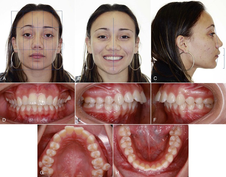
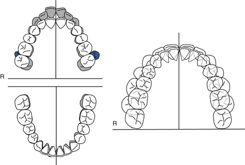
Figure 2-1 Case 1. A, Extraoral frontal view. Ovoid facial form; slight mentalis strain upon closure; no apparent pathology; interlabial gap 3.0 mm; 20% incisor display at rest clinically; midline—no major asymmetries; transverse fifths—normal intercommissural width at rest; vertical thirds—normal; mentolabial fold visible from this view. B, Extraoral smile. Incisor display on smile 90%; excessive mandibular incisor show; midlines: maxillary—0.5 mm right of facial, mandibular—on with facial; narrow smile. C, Extraoral profile. Convex soft tissue profile; protrusive upper lip; retrusive lower lip; lower facial height: throat depth within normal limits (WNL). D, Intraoral frontal view. Maxillary midline 0.5 mm to right of facial; mandibular midline on with facial; 40% overbite; good oral hygiene; slightly thin gingival biotype in lower incisor region. Intraoral right (E) and left (F) buccal views. Class II molar and canine (more severe on left); 7 mm overjet; protrusive maxillary and mandibular incisors. G, Intraoral maxillary occlusal view. 7–7 present with supernumerary teeth adjacent to molars; U-shaped arch; moderate crowding (5 mm); no caries present with some staining of pits and fissures. H, Intraoral mandibular occlusal view. 7–7 present; U-shaped arch; mild crowding (3 mm); small occlusal composites on lower 6s and staining of pits and fissures.
Medical History
Dental History
• Patient has received routine dental care.
• Presents in permanent dentition with second molar to second molar present in both arches.
• Minor occlusal restorations present on posterior teeth.
• History of supernumerary teeth resembling premolars present between maxillary first molar and second premolar.
Psychosocial Profile
Enthusiastic about receiving orthodontic treatment.
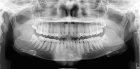
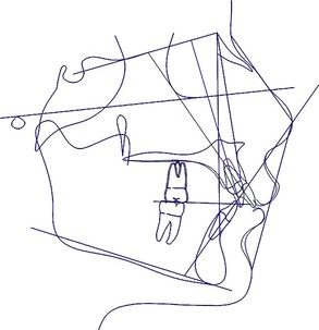
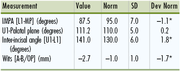
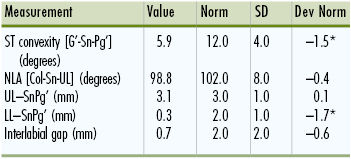
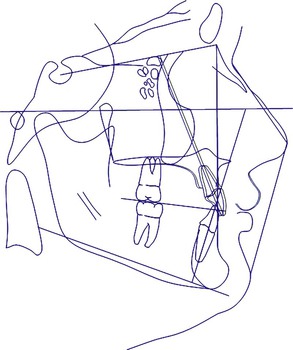
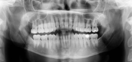
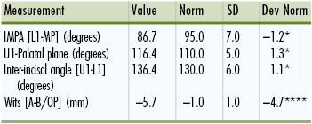
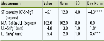
Cephalometric Summary (Fig. 2-3 and Tables 2-1 to 2-4)
Class II skeletal relationship with convex skeletal profile including:
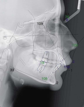
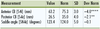
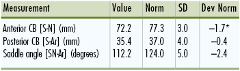
TABLE 2-1
Case 1: Cranial Base Analysis
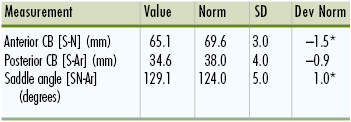
CB, cranial base; Dev Norm, deviation norm; SD, standard deviation. * indicates number of SD from norm values.
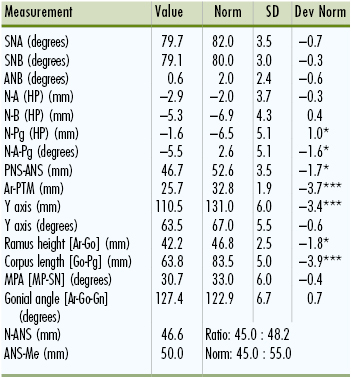
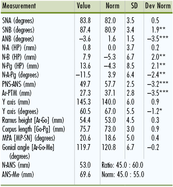
TABLE 2-2
Case 1: Maxilla-Mandible to Cranial Base Analysis
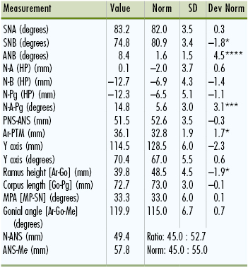
ANB, A point nasion B point; ANS, anterior nasal spine; Dev Norm, deviation norm; HP, horizontal plane; MPA, mandibular plane angle; PNS, posterior nasal spine; PTM, pterygomaxillary point; SD, standard deviation; SNA, sella-nasion A point; SNB, sella-nasion B point. * indicates number of SD from norm values.
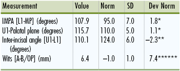
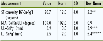
• Convex and Class II skeletal and soft tissue profile.
• Supernumerary teeth in maxilla adjacent to first molars.
Problem List
1. Medical and dental findings of significance:
• Supernumerary teeth adjacent to maxillary first molars
• Small occlusal composite restorations on posterior dentition
• Thin gingival biotype in lower incisor region
• Skeletal: Class II and convex skeletal profile due to retrognathic mandible
• Dental: (1) Class II, Division 1 malocclusion (end-on on right, full-cusp on left); (2) severe Class II denture base discrepancy; (3) protrusive maxillary and mandibular incisors; (4) 7-mm overjet
• Skeletal: Slightly short ramus height, vertical thirds within normal limits
• Dental: (1) 40% overbite; (2) 3-mm interlabial gap at rest, 20% incisor display at rest, 90% incisor display at smile; (3) Slightly accentuated lower curve of Spee
• Skeletal: Normal skeletal transverse dimensions
• Dental: (1) Maxillary midline 0.5-mm to the right of mandibular dental midline; mandibular midline on with facial midline.
• Maxillary arch: moderate (5-mm) crowding
• Mandibular arch: mild (3-mm) crowding
Treatment Objectives (Figs. 2-4 and 2-5)
1. Significant medical and dental objectives:
• Educate patient on smoking cessation and provide options
• Extract supernumerary teeth in maxillary arch and all four third molars
• Continue to provide oral hygiene instructions and monitor
2. Skeletofacial: Reduce convexity of profile with camouflage treatment
• Incisors: (1) Retract the maxillary incisors; (2) maintain mandibular incisor position
• Molars: (1) Maintain the maxillary molar position with maximum anchorage; (2) maintain mandibular molar position
• Incisors: (1) Maintain maxillary incisor position; (2) maintain mandibular incisor position
• Molars: (1) Maintain maxilla; (2) minor extrusion of mandibular molars for leveling of lower curve of Spee
5. Arch width/transverse: Maintain transverse dimensions
6. Midlines: Correct alignment of maxillary incisors to coincide midlines
General Treatment Plan (Table 2-5)
• Extract supernumerary teeth, third molars, and maxillary first premolars
• Maximum direct anchorage in maxillary arch with infrazygomatic mini-implants for intrusion and retraction of maxillary incisors
TABLE 2-5
Case 1: Orthodontic Treatment Sequence
| Maxilla | Mandible |
| Consultation and Place Separators; Refer for Extraction of Maxillary First Premolars, Supernumerary Teeth, and Third Molars | |
| Band first molars and bond remaining teeth | Band first molars and bond remaining teeth |
| Level and align | Level and align |
| Place infrazygomatic mini-implants (LOMAS*, 2 mm × 9 mm) | |
| En masse intrusion/retraction with 200-g Ni-Ti coil springs from mini-implants to soldered hooks on archwire (distal to lateral incisors) (Group A left, Group B right) | |
| Finish | Finish |
| Retention (circumferential Hawley retainer) | Retention (fixed lingual retainer) |
* Mondeal Ortho, Mühlheim, Germany.
Ni-Ti, Nickel-titanium.
Treatment Progress
Patient was cooperative with oral hygiene and appliances throughout treatment and experiences no complications with the mini-implants. The patient was treated with 0.022-inch × 0.028-inch slot Carriere brackets with MBT prescription (Ortho Organizers Inc., Carlsbad, CA.). Once aligned, a 0.019-inch × 0.025-inch stainless steel wire was placed in the maxillary with soldered hooks between the maxillary lateral incisors and canines. Two infrazygomatic 2-mm × 9-mm mini-implants (LOMAS, Mondeal Ortho, Mühlheim, Germany) were placed with 200-g nickel-titanium (Ni-Ti) closed coil springs to the soldered hooks for en masse retraction of maxillary anterior teeth (Fig. 2-6). A canine Class I relationship was achieved within 8 months and the remaining space was closed in 4 months. The patient finished Class I canine, Class II molar and was given a circumferential wrap-around retainer for the maxillary arch and a lower fixed lingual retainer (Fig. 2-7).
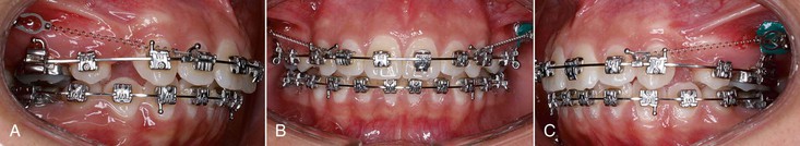
Figure 2-6 Case 1. Interim intraoral photographs after placement of infrazygomatic mini-implants and 200-g nickel-titanium (Ni-Ti) closed coil spring to soldered hooks to begin en masse retraction and intrusion. Right buccal (A), frontal (B), and left buccal (C) views.
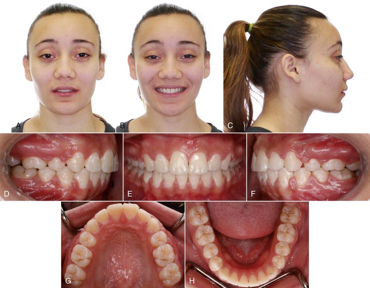
Figure 2-7 Case 1. Final records. A, Extraoral frontal view. B, Extraoral smile view. C, Extraoral lateral view. D, Intraoral right buccal view indicated Class II molar and Class I canine occlusion and ideal incisor relationship. E, Intraoral frontal view indicated improved overbite and overall improvement in esthetics. F, Intraoral left buccal view. Maxillary (G) and mandibular (H) occlusal views.
Case Report 2
Overview
This case illustrates the complexity of managing impacted teeth from an orthodontic perspective. The fundamental component in developing a treatment plan in such cases is proper localization of the impacted teeth and determining the likelihood of aligning these teeth through a combined periodontal-orthodontic approach.
Radiographs are an important tool for determining whether a surgical approach is required and where to gain access to the impacted tooth. Numerous radiographic methods have been described in the literature using a combination of panoramic, periapical, and occlusal radiographs. Consecutive periapical x-rays with an incorporated mesial shift is widely used to determine the buccal or palatal position of impacted teeth by the application of Clark's SLOB (Same Lingual, Opposite Buccal) rule.33 The primary limitation of traditional radiographs is that they are 2D representations and the localization of the impacted tooth can be challenging due to overlapping structures and distortion. Nearly 80% of clinicians need to use two or more supplemental radiographs to localize an impacted tooth.34
There are numerous benefits to using 3D imaging modalities with CBCT. Use of CBCT can be prescribed on a case-by-case basis; cases with impacted teeth are ideal for CBCT due to the orthogonal 1 : 1 representation and the ability to view the tooth successive slices, which eliminates the problem of overlapping adjacent teeth and other structures.35,36 In addition, in cases where the impacted tooth is impinging on the adjacent tooth's root, root resorption can occur and be difficult to ascertain in both panoramic and intraoral images.37,38 For these reasons, an accurate depiction of the true clinical position of the impacted teeth and potential compromise of adjacent teeth is greatly valuable and has a profound impact on the final treatment plan for the patient.
The small-volume CBCT has gained popularity, specifically since it further reduces the radiation dose from the traditional CBCT, focusing on only a small and focused field of view, such as 50-mm × 37-mm used in this case. Limiting this field of view to the area of interest can reduce the radiation dose to the patient but still provide the needed 3D information. A comparison of 14 CBCT devices showed significantly lower radiation exposure with small-volume CBCT compared to traditional full field of view CBCTs.39 Based on that study, the Kodak 9000 3D CBCT (Kodak Dental Systems, Carestream Health, Rochester, NY.) used in this case had the lowest overall dose of radiation of the machines tested, with an effective dose of 19µSv in the anterior maxillary region. Conventional intraoral radiographs for detecting impacted canines include two periapicals or an occlusal x-ray, which have effective doses of 10µSv and 7µSv, respectively.40,41
Having 3D imaging of specific areas of interest aids the operator in exposing the correct part of the tooth and also in determining the placement of the bracket or gold chain. It also aids in developing the biomechanics plan to determine the most efficient way to orthodontically align these teeth.
Patient Profile (Figs. 2-8 and 2-9)
• 16.6-year-old, postpubertal female.
• Chief complaint: “Save my teeth. The bite is not good on the left.”
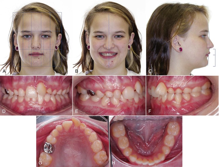
Figure 2-8 Case 2. A, Extraoral frontal view at rest. Ovoid facial form; vertical thirds normally proportioned; transverse fifths within normal range; nose and chin point on with facial midline; no maxillary incisor display at rest; no interlabial gap at rest. B, Extraoral smile. Maxillary incisor display on smile of 100%; 1–4 mm of gingival display upon smile; asymmetrical flat smile arc; upper and lower midlines coincident and on with facial midline on smile. C, Extraoral profile. Orthognathic facial profile with prominent chin button; retruded lower lip; nasolabial angle within normal range; slightly deep mentolabial fold; vertical thirds within normal proportions. D–H, Intraoral views. D, Intraoral frontal view. Maxillary and mandibular midlines coincident with facial midline; 70% overbite; fair oral hygiene; peg-shaped maxillary right lateral incisor; multiple deciduous teeth visible. E and F, Intraoral buccal views. Bilateral Class I relationship. G, Intraoral maxillary occlusal view. Retained deciduous teeth present: canines and second molars, left lateral incisor and left first molar; stainless steel crown on right deciduous second molar; sealants on first permanent molars and left deciduous second molar; U-shaped arch; adequate space for impacted teeth. H, Intraoral mandibular occlusal view. Retained deciduous second molars; mild crowding of 2 mm; U-shaped arch.
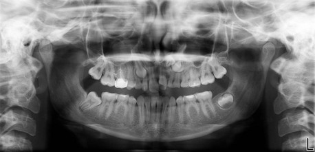
Figure 2-9 Case 2. Panoramic radiograph. Multiple impacted teeth visible in maxillary arch. Agenesis of second premolars in all quadrants. Developing third molars in maxillary and mandibular left quadrants. Agenesis of mandibular left second molar and mesial inclination of mandibular right second molar.
Dental History
• Extensive dental care and routine oral hygiene visits
• Deciduous teeth present: Maxillary canines, second molars, left lateral incisor, and left first molar; mandibular second molars
• Permanent teeth missing: Maxillary and mandibular second premolars and right maxillary and mandibular third molars and mandibular second molar
• Restorations present: Occlusal composite on mandibular deciduous second molars, root canal treatment and stainless steel crown on maxillary deciduous right second molar, and sealants on first molars
Psychosocial Profile
Patient is cooperative and enthusiastic to begin treatment. She is very self-conscious and concerned about her teeth.
Cephalometric Summary (Fig. 2-10 and Tables 2-6 to 2-9)
• Orthognathic, Class I skeletal and soft tissue profiles
• Mesofacial, with normal vertical thirds
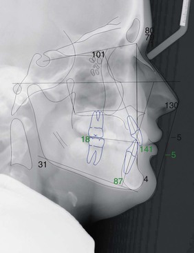
TABLE 2-6
Case 2: Cranial Base Analysis
CB, cranial base; Dev Norm, deviation norm; SD, standard deviation. * indicates number of SD from norm values.
TABLE 2-7
Case 2: Maxilla-Mandible to Cranial Base Analysis
ANB, A point nasion B point; ANS, anterior nasal spine; Dev Norm, deviation norm; HP, horizontal plane; MPA, mandibular plane angle; PNS, posterior nasal spine; PTM, pterygomaxillary point; SD, standard deviation; SNA, sella-nasion A point; SNB, sella-nasion B point. * indicates number of SD from norm values.
Overall Summary
• Class I skeletal and soft tissue profile
• Class I occlusion, 2-mm overjet
• Multiple impacted teeth in maxillary arch and retained deciduous teeth
• Retained second primary molars in all four quadrants with agenesis of second premolars, mandibular left second molar and maxillary and mandibular right third molars
Interpretation of Small-Volume CBCT (Fig. 2-11)
The small-volume CBCT was acquired at a voxel size of 76 µm, providing sufficient resolution to localize the unerupted teeth and adjacent structures. The images showed that the permanent left maxillary lateral incisor was horizontally impacted and was located lingual to the root of deciduous left lateral incisor and oriented in the buccolingual direction. Notable apical root resorption was detectable on the maxillary left deciduous canine and ectopic eruption of the maxillary left permanent canine. The maxillary left second premolar was also horizontally impacted in the buccolingual direction with notable apical root resorption on the maxillary left deciduous first molar.
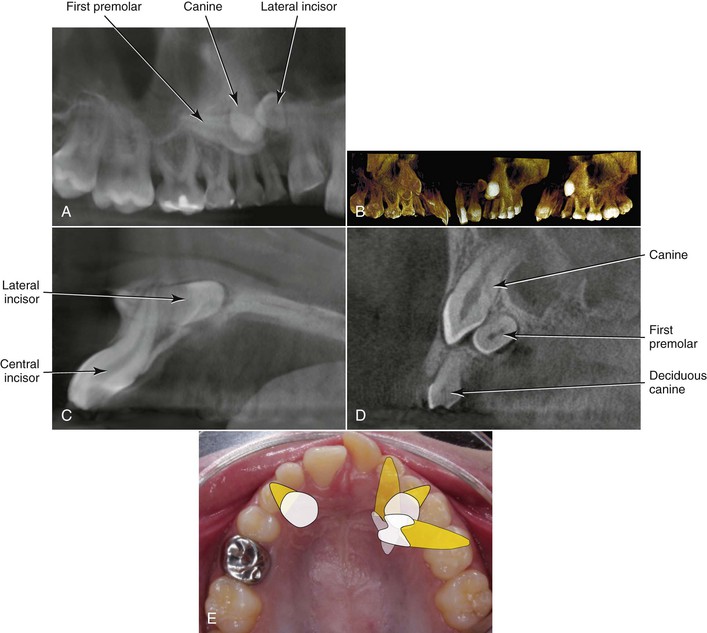
Figure 2-11 Case 2. Small-volume cone beam computed tomography (CBCT) of maxillary left quadrant. A, View from an oblique angle from the palatal aspect; the lateral incisor crown is pointing distal and horizontally impacted. The first premolar is also horizontally impacted, pointing toward the lateral incisor crown. B, Volume-rendered views from a direct palatal view (left panel), frontal view (center panel), and buccal view (right panel). Successive sagittal slices at the level of the left central incisor (C) indicating that the apex of the lateral incisor closely approximates the buccal cortex. At the level of the impacted canine (D), the horizontal impaction of the first premolar is evident, palatal to the canine. E, Schematic rendition of the impacted teeth from an occlusal clinical view.
1. Medical and dental findings of significance:
• Impacted maxillary permanent canines, right lateral incisor, and right first premolar
• Presence of numerous deciduous teeth
• Agenesis of second premolars and mandibular left second molar
• Agenesis of right maxillary and mandibular third molars; evidence of third molar follicles in upper left and lower left quadrants
• Peg-shaped upper right lateral incisor
• Dilaceration of maxillary left central incisor
• Mesial inclination of mandibular right second molar
• Maxillary gingival height discrepancy and mild localized gingivitis in maxillary left quadrant
• Maxillary arch: Adequate spacing; impacted maxillary canines, right lateral incisor and right first premolar
• Mandibular arch: (1) Mild crowding (2 mm); (2) Bolton discrepancy (mandibular excess 1–2 mm).
• Skeletal: Normal vertical thirds
• Dental: (1) No incisor shown at rest; (2) 70% deep bite
• Skeletal: Within normal limits; orthognathic
• Dental: (1) 2-mm overjet; (2) upright upper incisors, retroclined lower incisors
Treatment Objectives (Figs. 2-12 and 2-13)
1. Significant medical and dental objectives:
• Continue to monitor eruption of the developing mandibular molars; upright mandibular right second molar to correct inclination
• Extract deciduous maxillary canines, deciduous maxillary second molars, deciduous maxillary left lateral incisor, and deciduous maxillary left first molar
• Maintain deciduous mandibular second molars with 1-mm interproximal reduction
• Periodontal exposure of palatally impacted maxillary left lateral incisor and first premolar, with orthodontic traction to erupt
• Monitor dilacerated maxillary left central incisor and refer to endodontist for evaluation.
2. Skeletofacial: Maintain facial harmony.
• Incisors: (1) Maintain upper incisor position; (2) upright lower incisors
• Molars: (1) Maxilla: Group C anchorage with 5-mm molar protraction; (2) mandible: Protract molars 2-mm. Finish with Class II molar relationship.
4. Arch width and transverse: Maintain transverse dimension.
• Incisors: Maintain maxillary incisor position; relative intrusion of mandibular incisors
• Molars: Maintain maxillary molar vertical position; level lower curve of Spee through some extrusion of posterior dentition
General Treatment Plan (Table 2-10)
• Treat as maxillary premolar extraction case by closing E spaces in maxillary arch.
• Surgically expose impacted maxillary canines and left first premolar and extract respective deciduous teeth in maxillary arch. Begin orthodontic traction of impacted teeth. Once the left first premolar is partially aligned and the lateral incisor is accessible surgically, send for exposure and begin traction.
• If impacted teeth are ankylosed and do not respond to orthodontic traction, extract and place implants.
TABLE 2-10
Case 2: Orthodontic Treatment Sequence
| Maxilla | Mandible |
| Refer patient to periodontist for consultation and exposure of impacted left first premolar and canines. Determine timing of exposure for left lateral incisor. Extract deciduous first and second molars, canines, and left lateral incisor. | Maintain lower deciduous second molars and continue to monitor. |
| Band 6s. Bond 7-7 | Band 6s. Bond 7-7 |
| Alignment and leveling. Orthodontic traction and alignment for maxillary left first premolar and canines; once initial alignment of first premolar is complete and the left lateral incisor is accessible, send patient for surgical exposure. | Alignment and leveling |
| Group A space closure | |
| Finish Class II molar and canine | Finish Class II molar and canine |
| Retention | Retention |
Case Report 3
Overview
This case illustrates the use of 3D virtual planning in surgical orthodontics, specifically in an asymmetrical patient. In addition, the “surgery first” method is employed. While in traditional orthognathic surgery cases there is a three-phase approach (presurgical orthodontics, surgery, and postsurgical orthodontics), the “surgery first” approach eliminates the first of these phases of treatment, thereby reducing the patient's overall treatment time. This method is detailed fully in Chapter 21.
Patient Profile (Figs. 2-14 and 2-15)
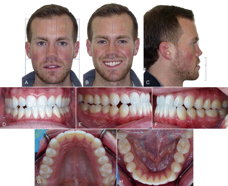
Figure 2-14 Case 3. A, Extraoral frontal view. Normofacial with ovoid facial form; chin point 7–8 mm to left of facial midline; maxillary dental midline on with facial midline; 7-mm interlabial gap at rest with 30% to 40% maxillary incisor display. B, Extraoral smile. 100% incisor display; maxillary cant evident with excessive gingival display in maxillary right quadrant; slight asymmetry of lips on animated smile. C, Extraoral profile. Concave soft tissue profile; nasolabial angle within normal limits; upper facial height to lower facial height 40 : 60; protrusive lower lip to Sn-Pg'. D–H, Intraoral views. D, Intraoral frontal view. Maxillary midline on with facial; mandibular midline 1–2 mm to left of facial; minimal overbite 10%; elongated lower incisors. E and F, Intraoral right and left buccal views. Class III malocclusion (full cusp on right,  cusp on left); 1–2-mm negative overjet; compensated occlusion. G, Intraoral maxillary occlusal view. Second molar to second molar present; U-shaped arch; no crowding and healthy dentition. H, Intraoral mandibular occlusal view. Second molar to second molar present; U-shaped arch; minor spacing (~1 mm) distal to left lateral incisor.
Dental History
• Patient has received routine dental care and reports prior history of orthodontic treatment.
• Presents in permanent dentition with second molar to second molar present in both arches.
• Large occlusal restoration on mandibular left first molar and maxillary second molars.
Psychosocial Profile
Highly enthusiastic and motivated patient with high esthetic expectations
Cephalometric Summary (Fig. 2-16 and Tables 2-11 to 2-14)
Class III skeletal relationship with concave skeletal profile including:
• Prognathic mandible relative to cranial base
• Compensated occlusion with proclined maxillary incisors and retroclined mandibular incisors
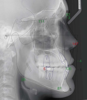
TABLE 2-11
Case 3: Cranial Base Analysis
CB, cranial base; Dev Norm, deviation norm; SD, standard deviation. * indicates number of SD from norm values.
TABLE 2-12
Case 3: Maxilla-Mandible to Cranial Base Analysis
ANB, A point nasion B point; ANS, anterior nasal spine; Dev Norm, deviation norm; HP, horizontal plane; MPA, mandibular plane angle; PNS, posterior nasal spine; PTM, pterygomaxillary point; SD, standard deviation; SNA, sella-nasion A point; SNB, sella-nasion B point. * indicates number of SD from norm values.
Overall Summary
• Concave, Class III skeletal and soft tissue profile
• Class III molar and canine occlusion with
• Maxillary cant with slightly excessive gingival display on the right on smile
Problem List
1. Medical and dental findings of significance:
• Incidental finding on CBCT: Lesion on the base of the skull (clivus) (Fig. 2-17)
• Referred patient to medical radiologist for magnetic resonance imaging (MRI); lesion was 12.0 × 8.5 × 8.5 mm and determined to be likely of chondroid origin and nonaggressive
• Recommended to recall for reevaluation with radiology in 6 months and clearance given to proceed with orthognathic surgery
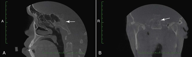
Figure 2-17 Case 3. Cone beam computed tomography (CBCT) images indicate lesion on base of the skull. Images acquired with Hitachi CB MercuRay CBCT scanner (Hitachi Medical Corp., Tokyo, Japan). A, Sagittal section with arrow pointing to lesion in the area of the clivus. B, Coronal section with arrow pointing to lesion.
• History of rhinoplasty and previous orthodontic treatment during adolescence
• Skeletal: Class III and concave skeletal profile due to prognathic mandible
• Dental: (1) Class III malocclusion (full cusp on right,  cusp on left); (2) severe Class III denture base discrepancy; (3) compensated incisors with proclined maxillary incisors and retroclined mandibular incisors; (4) 1–2-mm negative overjet
• Skeletal: Maxillary cant present, indicated by excessive gingival display in maxillary right quadrant
• Dental: (1) 10% overbite; (2) 7-mm interlabial gap at rest, 30% to 40% incisor display at rest, 100% incisor display visible on smile
• Skeletal: Mandibular asymmetry, with chin point deviated to the left 3-mm relative to facial midline
• Dental: (1) Maxillary midline 1 mm to the left of facial midline; mandibular midline 2-mm to the left of facial midline
• Maxillary arch: No crowding or spacing
• Mandibular arch: 1-mm spacing (distal to left lateral incisor)
Treatment Objectives (Figs. 2-18 and 2-19 and Table 2-15)
1. Significant medical and dental objectives:
• Ensure that patient continues to be monitored by medical radiology for management of lesion on clivus
• Refer patient to oral and maxillofacial surgeon and ensure that patient is aware of the risks of surgical intervention
• Continue to provide oral hygiene instructions and monitor
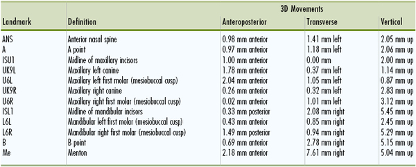
• Anteroposterior: Correct Class III and concave skeletal and soft tissue profile with bilateral sagittal split osteotomy (BSSO) and asymmetrical setback of the mandible (3-mm on right, 0.5-mm on left) and Le Fort I osteotomy
• Vertical: Correct maxillary cant with asymmetrical maxillary osteotomy and impaction (3-mm on right, 1-mm on left)
• Transverse: Correct lower midline deviation with asymmetrical BSSO setback (see above). Lateral sliding genioplasty to shift chin point 7–8 mm to right.
• Incisors: (1) Reduce maxillary incisor proclination; (2) procline lower incisors
• Molars: Finish Class I molar and canine
• Incisors: Maintain maxillary and mandibular vertical incisor position postsurgery
• Molars: Maintain vertical molar position postsurgery
5. Arch width and transverse: Maintain transverse dimensions
6. Midlines: Maintain dental position postsurgery
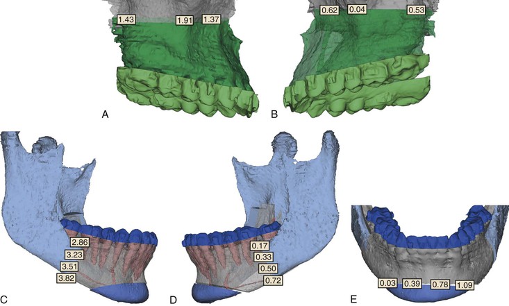
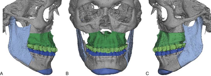
Figure 2-18 Case 3. Virtual 3D planning of surgical movements using Simplant OMS software (Materialise, Leuven, Belgium). A and B, Maxillary surgical movements from right and left views; Le Fort I osteotomy with asymmetrical impaction, indicating greater impaction on right. C and D, Mandibular surgical movements with right and left views; asymmetrical bilateral sagittal split osteotomies with greater setback on the right side. E, Lateral sliding genioplast for correction of chin point deviation with some vertical correction on left.
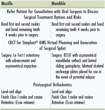
General Treatment Plan (Table 2-16)
• Orthodontic appliances placed 4 weeks prior to surgery.
• “Surgery first” approach (2 jaw): Le Fort I osteotomy (maxillary advancement, asymmetrical impaction), BSSO with asymmetrical mandibular setback and lateral sliding genioplasty. Immediate postsurgical occlusion will be overcorrected slightly to accommodate for dental decompensation during postsurgical orthodontics.
• Postsurgical orthodontics to finish Class I molar and canine with decompensation and final seating of occlusion.
Treatment Progress
The patient was bonded with 0.022-inch × 0.028-inch slot twin brackets with MBT prescription and 0.016-inch × 0.016-inch Ni-Ti maxillary and mandibular archwires with surgical hooks were placed in the operating room immediately prior to surgery. The computer-aided design (CAD)–generated surgical splints (Fig. 2-20) were removed immediately postsurgery. Two weeks after surgery the surgical hooks were removed, light Ni-Ti wires were placed, and the patient began wearing intermaxillary elastics. Orthodontic treatment lasted a total of 7 months Postoperative records show improvement in the facial profile overall and reduction in the asymmetry (Fig. 2-21). The patient was satisfied with the esthetic results and short treatment time.
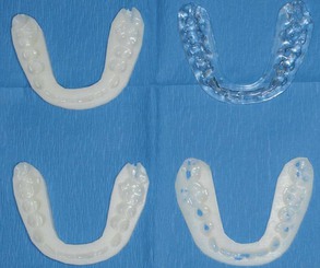
Figure 2-20 Case 3. Generation of intermediate and final surgical splints based on computer-generated 3D plan using computer-aided design (CAD) software and produced on a stereolithographic rapid prototyping machine (Medical Modeling, Golden, CO.).
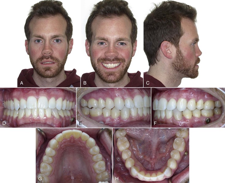
Figure 2-21 Case 3. Final records. A, Extraoral frontal view with improvement in asymmetry of chin. B, Extraoral smile with improvement in maxillary cant. C, Extraoral profile with notable improvement in facial proportions and convexity. D, Intraoral frontal photo with correction of anterior crossbite and more overbite. E and F, Right and left buccal view showing Class I molar and canine occlusion with ideal overjet and overbite. G and H, Maxillary and mandibular occlusal views showing improved alignment overall.
Summary
This chapter described a systematic way to diagnose an orthodontic patient, devise a list of treatment objectives, and, based on that information, develop an individualized treatment plan. Specific treatment objectives provide the blueprint for the desired outcome. The importance of having specific objectives is highlighted when a decision is needed among the myriad of orthodontic appliances for correction of any malocclusion.
To obtain a consensus between the wishes of the patient and the clinician, more than one treatment plan is often developed. Different treatment plans give the patient options that may be helpful when difficult choices must be made due to issues related to finances, compliance, or other personal circumstances. Therefore, in instances where treatment plans are developed, the pros and cons of each option should be evaluated. An evaluation of the different options will help the clinician to successfully present the treatment plan to the patient as well as to obtain informed consent.
Once the treatment plan has been defined with specific goals, the appliance or group of appliances needed to achieve these goals is selected. Although the mechanics plan is done after the treatment objectives have been set, many seasoned clinicians tend to be biased by their own experience as to what can be achieved with the tools (appliances) they traditionally use. It is important to understand the biomechanics and potential side effects of all appliances chosen for treatment in order to achieve the desired treatment goals. A solid understanding of the effects of each appliance, when applied to specific populations, is essential as well. Knowledge of scientifically controlled trials that study various orthodontic appliances in different populations will help to achieve this goal.42 Overall, it is important to remember that evidence-based orthodontics in conjunction with sound biomechanical knowledge allows the clinician to develop individualized mechanics with predictable results.
References
1. Roberts WE, Hohlt WF, Baldwin JJ. Adjunctive orthodontic therapy in adults: biologic, medical, and treatment considerations. Bishara SE. Textbook of Orthodontics. WB Saunders: Philadelphia, PA; 2001:494–531.
2. van Venrooy JR, Proffit WR. Orthodontic care for medically compromised patients: possibilities and limitations. J Am Dent Assoc. 1985;111(2):262–266.
3. Lindauer S. Orthodontic treatment planning. Nanda R. Biomechanics in Clinical Orthodontics. WB Saunders: Philadelphia, PA; 1997:23–47.
4. Kuhlberg AJ, Glynn E. Treatment planning considerations for adult patients. Dent Clin North Am. 1997;41(1):17–27.
5. Proffit WR, Sarver DM. Treatment planning: optimizing benefit to the patient. Proffit WR, Sarver DM, White RP. Contemporary Treatment of Dentofacial Deformity. Mosby: St. Louis, MO; 2003:172–244.
6. Kuhlberg AJ. Steps in orthodontic treatment. Bishara SE. Textbook of Orthodontics. WB Saunders: Philadelphia, PA; 2001:232–245.
7. Bishara SE. Facial and dental changes in adolescents and their clinical implications. Angle Orthod. 2000;70(6):471–483.
8. Bjork A. Prediction of mandibular growth rotation. Am J Orthod. 1969;55(6):585–599.
9. Burstone C. The integumental profile. Am J Orthod. 1958;44:1–25.
10. Kocadereli I. Changes in soft tissue profile after orthodontic treatment with and without extractions. Am J Orthod Dentofacial Orthop. 2002;122(1):67–72.
11. Rains MD, Nanda R. Soft-tissue changes associated with maxillary incisor retraction. Am J Orthod. 1982;81(6):481–488.
12. Lamarque S. The importance of occlusal plane control during orthodontic mechanotherapy. Am J Orthod Dentofacial Orthop. 1995;107(5):548–558.
13. Nanda R, Margolis MJ. Treatment strategies for midline discrepancies. Semin Orthod. 1996;2(2):84–89.
14. Nanda R. The differential diagnosis and treatment of excessive overbite. Dent Clin North Am. 1981;25(1):69–84.
15. Rossouw P, Preston CB, Lombard CJ, Truter JW. A longitudinal evaluation of the anterior border of the dentition. Am J Orthod Dentofacial Orthop. 1993;104(2):146–152.
16. Little RM. Stability and relapse of dental arch alignment. Burstone C, Nanda R. Retention and Stability in Orthodontics. WB Saunders: Philadelphia, PA; 1993:97–106.
17. Torres M. Treatment objectives and treatment planning. Dent Clin North Am. 1981;25(1):27–41.
18. Sarver DM. The importance of incisor positioning in the esthetic smile: the smile arc. Am J Orthod Dentofacial Orthop. 2001;120(2):98–111.
19. Mejia-Maidl M, Evans CA. Soft tissue facial considerations and orthodontic treatment. Semin Orthod. 2000;6(1):3–20.
20. Peluso C, Kuhlberg A. The axial inclination of central incisors and its effects on the perception of the facial profile. [Paper presented at: Annual American Dental Association Meeting, Scientific Program] 2002.
21. Arnett GW, Jelic JS, Kim J, et al. Soft tissue cephalometric analysis: diagnosis and treatment planning of dentofacial deformity. Am J Orthod Dentofacial Orthop. 1999;116(3):239–253.
22. Aziz T, Nassar U, Flores-Mir C. Prediction of lower incisor proclination during Xbow treatment based on initial cephalometric variables. Angle Orthod. 2012;82(3):472–479.
23. Vasconcelos G, Kjellsen K, Preus H, Vandevska-Radunovic V, Hansen BF. Prevalence and severity of vestibular recession in mandibular incisors after orthodontic treatment. Angle Orthod. 2012;82(1):42–47.
24. Allais D, Melsen B. Does labial movement of lower incisors influence the level of the gingival margin? A case-control study of adult orthodontic patients. Eur J Orthod. 2003;25(4):343–352.
25. Melsen B, Allais D. Factors of importance for the development of dehiscences during labial movement of mandibular incisors: a retrospective study of adult orthodontic patients. Am J Orthod Dentofacial Orthop. 2005;127(5):552–561.
26. Burzin J, Nanda R. The stability of deep bite correction. Burstone C, Nanda R. Retention and Stability. WB Saunders: Philadelphia, PA; 1993:61–79.
27. Fiorelli G, Melsen B. The “3-D occlusogram” software. Am J Orthod Dentofacial Orthop. 1999;116(3):363–368.
28. Marcotte MR. The use of the occlusogram in planning orthodontic treatment. Am J Orthod. 1976;69(6):655–667.
29. Braun S. The extraction–nonextraction decision revisited. Am J Orthod Dentofacial Orthop. 1999;116(4):21A–22A.
30. Xia J, Ip HH, Samman N, et al. Computer-assisted three-dimensional surgical planning and simulation: 3D virtual osteotomy. Int J Oral Maxillofac Surg. 2000;29(1):11–17.
31. Swennen GR, Mollemans W, De Clercq C, et al. A cone-beam computed tomography triple scan procedure to obtain a three-dimensional augmented virtual skull model appropriate for orthognathic surgery planning. J Craniofac Surg. 2009;20(2):297–307.
32. Swennen GR, Mommaerts MY, Abeloos J, et al. A cone-beam CT based technique to augment the 3D virtual skull model with a detailed dental surface. Int J Oral Maxillofac Surg. 2009;38(1):48–57.
33. Jacobs SG. Radiographic localization of unerupted maxillary anterior teeth using the vertical tube shift technique: the history and application of the method with some case reports. Am J Orthod Dentofacial Orthop. 1999;116(4):415–423.
34. Southall PJ, Gravely JF. Vertical parallax radiology to localize an object in the anterior part of the maxilla. Br J Orthod. 1989;16(2):79–83.
35. Guerrero ME, Shahbazian M, Elsiena Bekkering G, Nackaerts O, Jacobs R, Horner K. The diagnostic efficacy of cone beam CT for impacted teeth and associated features: a systematic review. J Oral Rehabil. 2011;38(3):208–216.
36. Kapila S, Conley RS, Harrell WE Jr. The current status of cone beam computed tomography imaging in orthodontics. Dentomaxillofac Radiol. 2011;40(1):24–34.
37. Ericson S, Kurol PJ. Resorption of incisors after ectopic eruption of maxillary canines: a CT study. Angle Orthod. 2000;70(6):415–423.
38. Ericson S, Kurol J. Incisor resorption caused by maxillary cuspids. a radiographic study. Angle Orthod. 1987;57(4):332–346.
39. Pauwels R, Beinsberger J, Collaert B, et al. Effective dose range for dental cone beam computed tomography scanners. Eur J Radiol. 2012;81(2):267–271.
40. Patel S, Dawood A, Ford TP, Whaites E. The potential applications of cone beam computed tomography in the management of endodontic problems. Int Endod J. 2007;40(10):818–830.
41. Ngan DC, Kharbanda OP, Geenty JP, Darendeliler MA. Comparison of radiation levels from computed tomography and conventional dental radiographs. Aust Orthod J. 2003;19(2):67–75.
42. Huang GJ. Making the case for evidence-based orthodontics. Am J Orthod Dentofacial Orthop. 2004;125(4):405–406.