Chapter 13

Extraction
The process of solvent extraction is involved in the preparation of most drugs. Synthetic drugs or those produced by fermentation are often purified, or separated from the mother liquor by liquid–liquid extraction. Constituents contained within plant or animal tissues are also extracted by means of solvents, but a preliminary leaching process is usually necessary. Fixed oils may be obtained in this way, but are also removed by direct expression of the tissues, and volatile oils are separated by steam distillation. (See Chapter 16.)
With the advent of numerous synthetic drugs, the demand for drugs of natural origin is diminishing. Some plant and animal products still remain important, however, including alkaloids, glycosides and other sugar derivatives, spices, fixed and volatile oils, proteins and polypeptides. Separation of the active constituents is desirable for the following reasons:
Often a single chemical, such as hyoscine or reserpine, is isolated by the extraction process, and is obtained as a crystalline solid. Sometimes, however, the active principle consists of a number of chemical compounds each of which is desired in the final product. The extraction process may then be stopped short of isolating the pure substances and the drug is used as a dry extract, a viscous soft extract, a concentrated infusion or a tincture. These crude extracts are known as galenicals. They were once used much more extensively than they are at present and included also simple infusions and decoctions made by extraction of the raw material with hot or boiling water. They were intended for extemporaneous dispensing and were required to be freshly prepared, because they rapidly produced a deposit due to coagulation of inert colloidal material and readily supported microbial growth because they lacked preservatives. Suitable assays could not be applied to them, and they were therefore usually prepared from materials whose constituents had little pharmacological activity. Galenicals are now rarely made extemporaneously; their preparation is usually time consuming and uneconomical for small quantities, and they also need to be subject to adequate quality control.

Leaching Processes

The process of leaching has been discussed by Peck (1936). Two main methods are employed, termed maceration and percolation, both being operated as batch processes. The choice of method depends upon the physical characteristics of the raw material and upon economic considerations and is designated in the monographs of the official preparations. On an industrial scale, however, there is often little difference between the operations of the two methods.

Maceration

The general process, on a small scale, consists of placing the solid material to be extracted in a closed vessel with the whole of the menstruum, or extraction solvent, and allowing them to stand for seven days, shaking occasionally. The liquid is strained off and the marc, or solid residue, is pressed to remove as much solution as possible. The liquids so obtained are mixed and clarified by subsidence or filtration.
The solids must be in a suitable state of subdivision, either crushed or cut small, or in moderately coarse powder. Fine powders are not used because subsequent clarification would be difficult. Sufficient time is then allowed for the menstruum to penetrate the plant tissues and for the soluble components to diffuse out. Diffusion may be assisted by shaking, or on a large scale by stirring, in order to disperse the concentrated solution which would otherwise accumulate round the particles of solid material. A closed vessel is essential to prevent evaporation and batch variation.
At the end of the maceration process there should be a uniform concentration of active constituents in both the plant debris and in the solution surrounding it. The solution, sometimes called miscella, is then strained off through cloth or other suitable material and the maximum yield of liquid is obtained by expressing the marc; special presses are used for this purpose. The solution so obtained may be cloudy and may contain small particles of debris, and time must be allowed for any colloidal material to coagulate. Sometimes several weeks are needed for this purpose. Precipitated matter is then removed by filtration through a filter press or other suitable filter. If filtration is carried out too soon, the initially clear solution will become cloudy again due to further coagulation of colloidal material.

Percolation

In this process the raw material is packed into a column and the solvent is allowed to percolate through it. Although some materials may be packed into a percolator in the dry state, e.g. Ginger, most drugs require preliminary moistening. The solid material is mixed with sufficient solvent and the moist mass is allowed to stand for 4 hours in a well-closed vessel. This preliminary moistening is important because the dried tissues may swell on contact with the solvent and, if packed in the dry condition; subsequent swelling might reduce the porosity of the material and choke the column. This swelling would be particularly marked with solvents which are mainly aqueous, and the greater the swelling the larger the volume of solvent required for preliminary moistening. Subsequent packing into the percolator is also assisted, since the solvent displaces occluded air and enables the material to be more evenly distributed. If the material is not packed evenly, the percolating solvent will run mainly through the largest channels, resulting in inefficient extraction. Preliminary moistening also makes the fine particles less liable to be washed out of the column during percolation.
After allowing the moist mass to imbibe the liquid, it is packed evenly into the percolator. Fig. 13.1 illustrates a type of percolator used on a commercial scale. The drug is supported on a perforated metal plate covered with sacking or straw. The top of the apparatus is removable for charging the column with raw material and is provided with portholes for inspection and running in of solvent. At the base the outlet is fitted with a tap, and a pipe leads the percolate away for subsequent treatment or to the top of a second percolator in order to use the solvent more efficiently. On a small scale glass percolators can be used and the raw material is supported in a loose plug of tow or other suitable substance which has been previously moistened with solvent. In order to achieve even packing the moist material is introduced layer by layer, each one being lightly tapped with a rod or other suitable implement, to give even compression. The pressure to be exerted depends on the nature of the swollen material and its permeability. To prevent disturbance of the packed solids, a piece of filter paper may be place on top of them and weighted down with sand. If there is a risk of further swelling of the raw material, it is preferable to use a percolator that is slightly conical, as the sloping sides allow better expansion of the bed than would cylindrical columns. The latter have the added disadvantage that solvent often fails to permeate through material near the sides at the bottom.

image

Fig. 13.1 Commercial scale percolator (approximately 1 ton capacity).

After this preliminary maceration, the outlet is opened sufficiently of produce a controlled slow rate of percolation. The volume of percolate to be collected for a given weight of raw material depends upon the nature of the final product. For some tinctures prepared on a small scale, about three quarters of the volume of the finished product is collected and the marc is pressed, giving about 80–90 per cent of the final volume. If no assay is available for the extractive, the mixed products of percolation and expression are made up to volume with more of the menstruum. In some cases additional ingredients, e.g. glycerol, are added before the final adjustment is made. In the case of more potent tinctures the percolate is assayed and the calculated amount of menstruum required to give a product of the required strength is added. In this process the assumption is made that the marc will be exhausted of the active principles which are to be extracted and adjustment to volume is therefore justified. The marc is pressed only to avoid wastage of solvent. This is in contrast to the maceration process where the liquid expressed from the marc is assumed to be of equal strength with that separated by straining.

Reserved Percolation

Liquid extracts are more concentrated preparations than tinctures, and percolation to exhaustion will produce a preparation that is too dilute. It is therefore necessary to reduce the volume of the percolate by evaporation. In certain instances, e.g. Liquorice Liquid Extract, the whole of the percolate may be concentrated by evaporation, but in others thermolability of the active principle may preclude this. Moreover, evaporation of a dilute alcohol would remove alcohol at a faster rate than water with the result that the concentrated extract would be largely aqueous and probably incapable of retaining the extracted matter in solution.
This is overcome by reserving the first portion of the percolate, which contains the bulk of the active constituents, owing to the preliminary maceration. The rest of the percolate is collected separately, percolation being continued until some simple test shows that no more active principle is being leached out. This second, dilute, percolate is then evaporated by means of, for example, a climbing film evaporator or vacuum still. The percolate is evaporated to the consistency of a soft extract, so that almost all the water is removed. It may then be dissolved in the reserved portion, which is usually strongly alcoholic, without risk of precipitation.
On a commercial scale, percolation and evaporation of the percolate may be carried out simultaneously; sometimes, with simple solvents such as acetone, the condensed vapour from the evaporator may be returned to the top of the percolator to continue the extraction.

Choice of Leaching Process

Occasionally, a restricted volume of solvent must be used to leach a large amount of raw material, because of the small amount of active principle contained therein. In such a case the proportion of solvent to raw material is too low to permit effective percolation.
Operation of the process of percolation requires skill, care and frequent attention. On the other hand maceration requires little skill and is economical in time; it is efficient for drugs that are easily extracted and in such cases is the method of choice, provided that the product obtained is satisfactory.
Because of the inevitable wastage of rectified spirit, the manufacture of tinctures on a commercial scale frequently departs from the official procedures, and a method is used which combines maceration and percolation techniques. This follows what is called a ‘cover and run down’ technique, whereby the raw material is moistened with suitably diluted industrial methylated spirit, packed into a percolator and macerated for a few hours, after which the liquid is run off. The partially extracted material may then be covered with more solvent, macerated as before and a second volume of liquid collected. This process may be repeated several times, but the later, weaker, percolates may be used to start the extraction of a fresh batch of drug. Belladonna, ipecacuanha, senega and squill, may be extracted in this way. Since no preparation for internal use must contain methanol, the percolate is evaporated under reduced pressure until tests show the absence of this toxic substance (Sergeant, 1950). After assay for alkaloid or total solid content, the concentrated extract is diluted with water and ethanol to produce a liquid extract or tincture containing the correct concentration of alcohol and active principle. This process cannot be used for materials which contain volatile material or which undergo change during the evaporation stage. Cocillana, for example, would become resinous if evaporated to a soft extract, and it is extracted by reserved percolation, which also retains the characteristic odour of the product.

Factors Affecting the Efficiency of the Leaching Process

Pretreatment of The Raw material and the Mechanism of Leaching

Some preliminary treatment of the raw material is nearly always necessary in order to facilitate extraction of the active principles. Where these are contained in cells near the epidermis, drastic comminution is unnecessary, and bruising or slicing thinly is adequate before maceration. Further treatment could, indeed, lead to an inferior product due to loss of volatile constituents. Occasionally, the raw material needs to be freshly prepared; thus cardamom seed must be freshly removed from the fruit and used immediately after being bruised or coarsely powdered.
Tissues which yield their active principles less readily must be reduced to a powder before extraction and it is very important that this should produce material of the right particle size. The smaller this is, the greater will be the surface area exposed to the solvent, and the shorter will be the distance through which this must diffuse to reach the solute and extract it. Increasing the degree of comminution will therefore lead to a faster rate of extraction. The most suitable particle size, however, is not necessarily the smallest, and it will depend on the physical nature of the raw material and of the solvent employed. Hard, woody, materials that are leached by a solvent which causes little swel1ing of the tissues, can be reduced to a fine powder, e.g. ipecacuanha, which is extracted with 80 per cent alcohol. Tissues that swell in the solvent, however, would produce a bed of low permeability if similarly treated. Also, although the cell walls of organized drugs retard the leaching of active constituents, they perform a useful function in preventing the extraction of unwanted high molecular weight constituents. Rupture of a considerable proportion of the cells by reduction to a fine powder may therefore yield an excessive amount of inert material which could hinder subsequent purification of the active principle or render difficult the clarification of a galenical (Bull, 1935; 1936). Fine dry grinding may also affect the chemical properties of plant constituents and thereby initiate chemical reactions in which the active principle forms complexes with other cell constituents from which the pure compound becomes difficult to separate (Pirie, 1956).
If the cell walls remain intact, diffusion through them may be the rate determining step and this will be in accordance with Fick’s first law of diffusion (see Chapter 9). Extraction is not, however, always governed by molecular diffusion since dialysis and slow dissolution may be controlling factors (Karnofsky, 1949a). Other factors may also be important; for example, Othmer and coworkers (1955, 1959) demonstrated that, when soybean flakes are shaken with solvent, the oil extraction rate is controlled by capillary action within the broken cells. They showed the dependence of this upon the surface tension, density and viscosity of the solvent. Hydrostatic pressure, particle cohesion and convection currents are also important.
Dean et al. (1953) observe, however, that the rate of leaching finally depends upon the permeability of the cell wall. They suggest that Belladonna and Stramonium Tinctures may be rapidly prepared by passage of the drug suspended in the solvent through a colloid mill followed by clarification in a centrifuge. Another method which, on a small scale, might increase the efficiency of extraction of plant tissue is to subject the macerating material to ultrasonic vibration. Thompson and Sutherland (1955) postulated that this decreased interfacial resistance to mass transfer, increased the interfacial area by reducing particle size, and increased the rate of dispersion of active principle away from the interface into the bulk of the solvent. As has been said above, however, such methods may lead to the extraction of unwanted material.
Since the raw material must form a bed of adequate permeability the particle size distribution should be sufficiently narrow to achieve this. A wide distribution would lead to a low porosity, because the smaller particles would tend to fill the voids between the larger particles. For this reason the monographs of the official preparations indicate a suitable degree of comminution and reference should be made to the official classification of powders.

The Nature of the Solvent

The ideal solvent should be selective in dissolving only the wanted constituents, but is rarely if ever met. The commonest solvent, water, is almost nonselective and alcohol is often insufficiently so. In practice dilute alcohols are used for many extractions but in some cases stronger a1cohol may be necessary to avoid solution of unwanted substances of high molecular weight, such as gums.
Additional processing is occasionally needed in order to remove undesirable constituents. Thus, before extracting ergot alkaloids with acid alcohol, the powdered ergot must first be defatted with low-boiling-point petroleum. In other cases the extract may be defatted. Thus on a small scale, in making Nux Vomica Liquid Extract, a liquid–liquid extraction may be used; the percolate, after concentration, is heated and shaken with hard paraffin, which retains the fat on cooling. Nux Vomica can also be extracted by a ‘cover and run down’ process using boiling water. Several of these extractions, each lasting about a day, may be needed to extract an economical amount of alkaloid. The aqueous extract can then be separated from the oil, concentrated by evaporation and re-extracted with strong alcohol to remove unwanted colloidal material. Further evaporation gives a soft extract which, after assay, can be suitably diluted with alcohol to make the tincture.
If the solvent is to remain in the final product, it must be nontoxic. A number of liquids which are good solvents for the principles to be extracted may therefore be unsuitable for use. If, however, the solvent is to be removed by evaporation, freedom from toxicity is less important, provided that there is no hazard in its use. It must be completely volatilized during the evaporation process, but its boiling point should not be so low as to cause difficulties during the leaching process, which might necessitate the use of specially constructed equipment operating under pressure. The solvent should also be plentiful and cheap and have a low specific heat in order to reduce the cost of its removal. Preferably it should also be noninflammable. It should also have a low viscosity, for this facilitates the leaching of solute from the tissues, the percolation of solvent through the bed of the material and the pressing of the marc and subsequent handling of the solution. Concentration of the solution by evaporation is also influenced by the viscosity, since a high viscosity reduces the rate of heat transfer and increases the risk of overheating thermolabile solutes. A high solution viscosity also restricts the design of suitable evaporators.
For the solvent extraction of oils, such solvents as benzene, light petroleum, or trichloroethylene can be used, while ether is used for the extraction of Male Fern. Where traces of water might interfere with the extraction process, a water-miscible solvent, such as acetone, may be preferred. Acetone is used for the extraction of spices and Ginger Oleoresin. For Capsicum Oleoresin, however, alcohol may be preferred on an industrial scale, since a liquid–liquid extraction may be used later to get rid of water-soluble material. This is an alternative to percolation with acetone and removal of this, followed by cold extraction of the residue with alcohol.
Besides alcohol, hydrocarbons are also used to extract alkaloids. The raw material must, however, first be moistened with water or an alkaline solution to liberate the free alkaloidal base. This technique can be used to obtain reserpine, the moistened rauwolfia powder being extracted with hot benzene in a Soxhlet apparatus (Boehringer et al., 1957). Purification of an alkaloid may be facilitated by such a procedure. The extract as first obtained will consist of a mixture of compounds, often chemically related but of differing pharmacological activity. One or more of the alkaloids will need to be further extracted from this mixture, perhaps by a change of solvent. An alkaloid may be partitioned from solution in a hydrocarbon into acidified water. By careful adjustment of the pH of the aqueous extract, separation of closely related compounds can be achieved by further liquid–liquid extraction. Final purification of alkaloids may also be assisted by careful choice of the acid used to make a crystalline salt (Svoboda & Shahovsky, 1953).
Careful selection of solvent may be necessary, not only to achieve a maximum extraction of active principle, but also to prevent undue destruction during the extraction process (Campo & Gramling, 1953). Racemization may also be an undesirable result of poor choice of solvent (Carkhuff & Gramling, 1952).
Various workers have investigated the effect of adding surfactants to the solvent (Helman, 1969). Nonionic compounds in alcoholic solvents may improve the extraction of alkaloids and, by enhancing the imbibition of solvent by the vegetable tissue, lead to a more rapid extraction with increased selectivity for alkaloid (Butler & Wiese, 1953; Srivastava & Chadha, 1963). In comparing the different classes of surfactants however, Brochmann–Hanssen (1954) concluded that nonionic surfactants had little or no effect on the yield of alkaloid. He demonstrated that salts of cationic surfactants gave the best extraction, whereas anionic compounds were unsuitable due to solubilization and an increased permeability of the cell wall, although an ion exchange mechanism was postulated for cationic surfactants, many alkaloids being combined with cellular constituents such as acids, proteins and cell wall components (Witt et al., 1953). Such adjuvants can only be used where the alkaloids are to be further purified, otherwise they would be present in the final product.

Temperature

The use of elevated temperatures is often precluded by the thermolability or volatility of the active principle, or by an increased extraction of unwanted constituents. For the isolation of a pure thermostable compound, however, raising the temperature of the solvent has the effect of hastening the leaching process, owing to the increased rate of diffusion, stronger convection currents and better solubility of the active principles. An enhanced solvent action is also assisted by loss of the integrity of cell walls and membranes.
Both maceration and percolation processes are amenable to the use of hot solvent. Maceration is accomplished by heating the drug and solvent in a closed vessel, this modification being known as digestion. Hot solvent is sprayed over the bed of raw material in some industrial processes.
Occasionally it is necessary to subject the raw material to the action of hot solvent for an extended period of time, particularly when the solute is not readily soluble, or penetration of cellular tissue is slow. Such cases include the extraction of fixed oils from seeds and of alkaloids by means of such solvents as hydrocarbons, chloroform or methanol, and of ginger oleoresin with acetone.
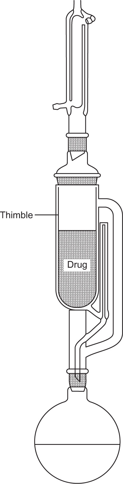
A small scale extraction apparatus is shown in Fig. 13.2. It consists of a flask, a Soxhlet extractor and a reflux condenser. The raw material is usually placed in a ‘thimble’ made of filter paper and inserted into the wide central tube of the extractor. Solvent is placed in the flask and boiled, its vapour passing up the large right hand tube into the central space above the drug and thence to the condenser. The condensate then drops back on to the drug, through which it percolates, leaching solutes in the process. When sufficient of the solution has collected to raise its level to that of the top of the siphon tube, shown on the right hand side, the whole of the collected percolate siphons over into the flask. The suction effect of the siphoning assists permeation of solvent through the drug. A limited amount of hot solvent is thus made to percolate repeatedly through the raw material, the solutes from which are transferred to the flask.

image

Fig. 13.2 Small-scale extraction apparatus.

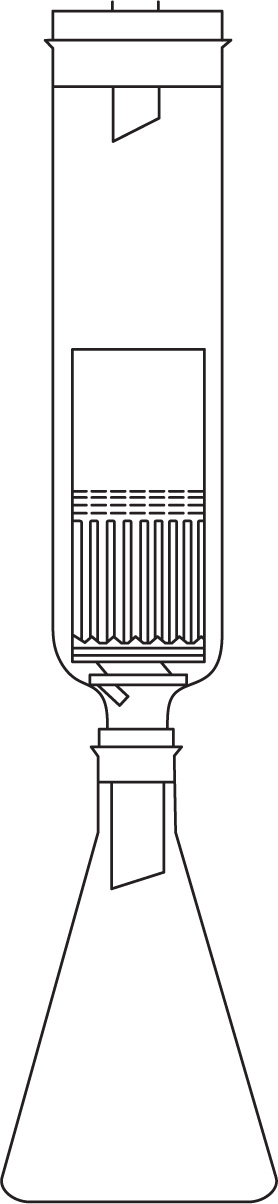
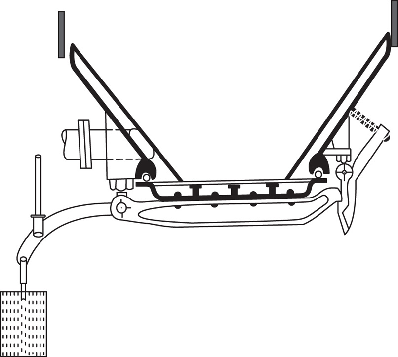
This principle of continuous hot extraction is sometimes used to extract a drug for the purposes of assay. A simple form of apparatus is described in the British Pharmacopoeia. It is shown in Fig. 13.3 and has the advantage that the hot, rising vapours encircle the material to be extracted, though the short period of maceration undergone in the Soxhlet apparatus is sacrificed.

image

Fig. 13.3 Apparatus for continuous extraction of drugs.

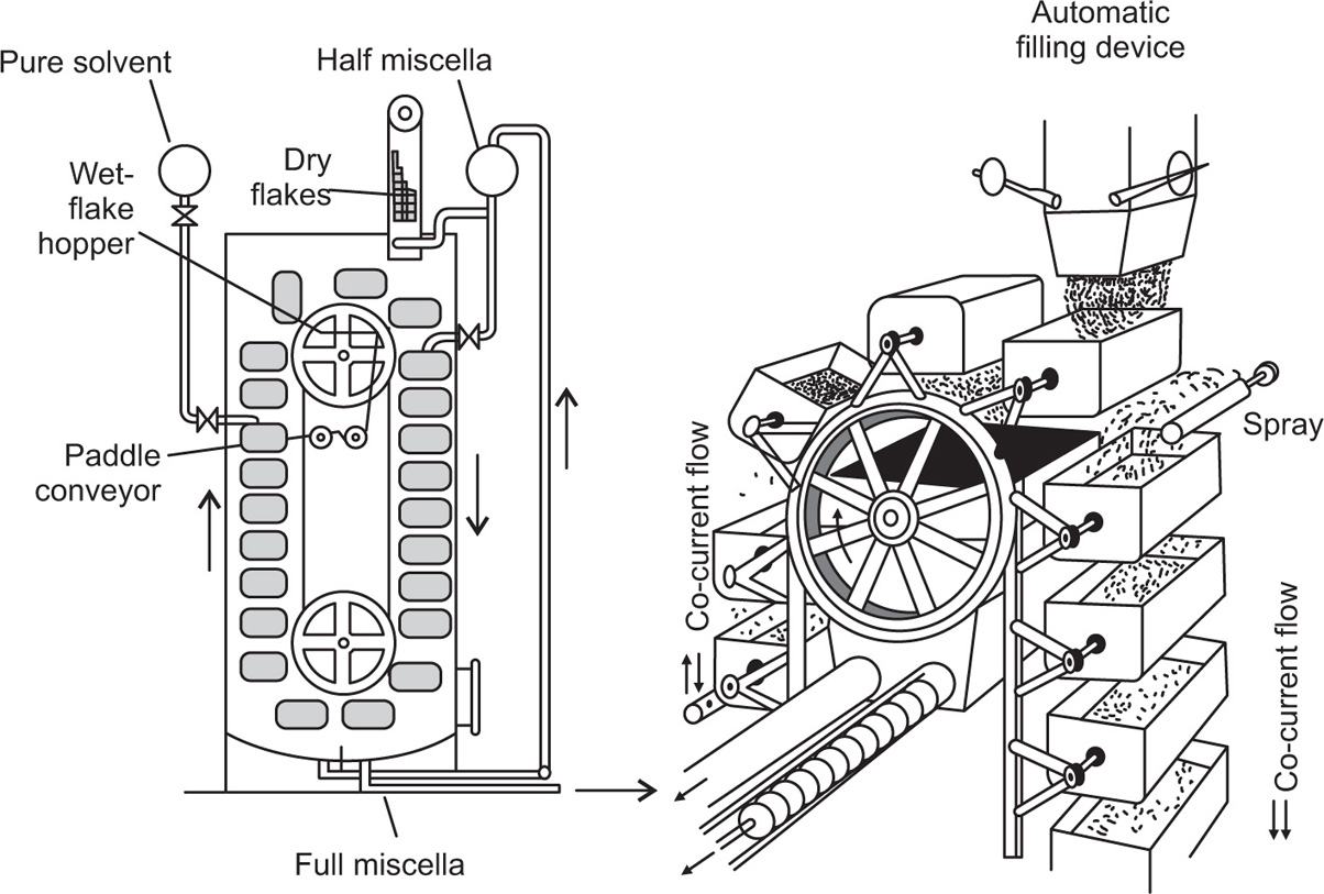
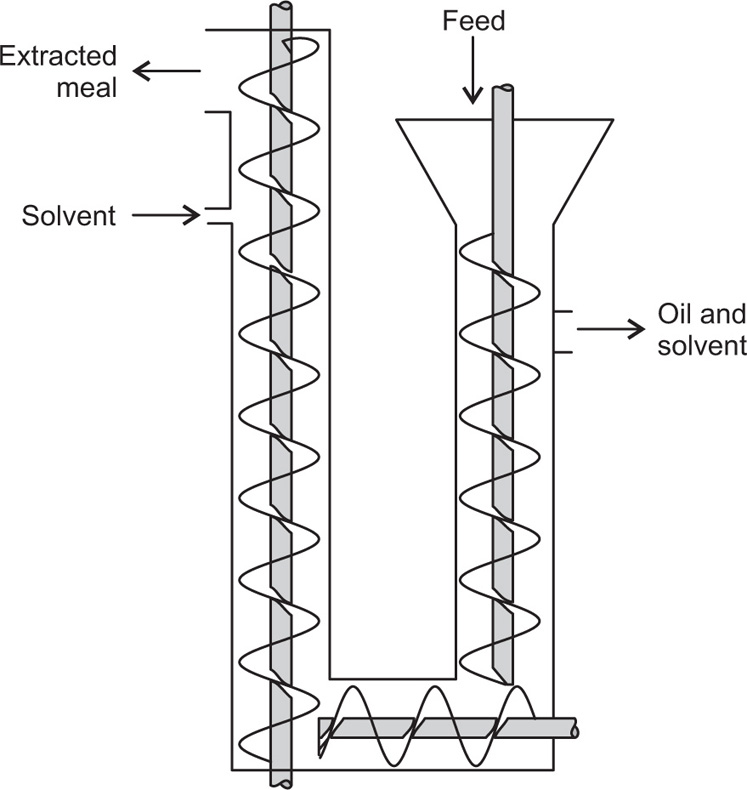
A large-scale plant has also been designed based on this principle.

Equipments for Leaching Coarse Solids

Open tanks and drag classifiers are two main classes of devices used for leaching coarse solids. The earliest and the simplest form of extraction apparatus, and one that is still used to an appreciable extent, is an open tank, containing a false bottom or filter of some sort. Into this tank, solid materials charged, the solvent is applied at the top and is allowed to percolate down through the charge, and is drawn off below the false bottom. In such tanks, the solvent is not simply distributed over the solid, but the entire tank is flooded with solvent. Filter bottoms are constructed in an endless variety of forms. Fig. 13.4 shows a few constructions. In A, perforated boards are laid on notched bearer strips on the bottom of the tank. In B, triangular pieces are laid on top of notched bearers, and the space between them is filled with gravel to act as a filter medium. In C, simple strips are used, spaced closely enough to retain the average lump of solid. In D, there is shown a method of constructing a cloth filter bottom that is often convenient. Notched bearer strips are laid on the bottom of the tank at intervals of a few inches. A band and or hoop is fastened to the bottom of the tank from half an inch to an inch inside the wall. The filter cloth is cut large so that it lies over the space between this hoop and the side of the tank and is then made tight by caulking a hemp rope into the groove. In some cases, the rate of solution is sufficiently higher so that one passage of the solvent down through the material gives a satisfactory extraction. After a wash with fresh solvent to remove adhering solution, the solid can be discarded. Such tanks have often been built for manual discharge, but it is more satisfactory to provide either side or bottom doors through which the solid can be flushed with a hose.

image

Fig. 13.4 Tank filter-bottom construction: (A) perforated boards on bearers; (B) support for gravel filter; (C) support for coarse material or filter cloth; and (D) method of securing filter cloth.

In the one-tank method of extraction, the most concentrated solution that can usually be made is relatively dilute. If it is necessary to prepare a stronger solution than this, counter-current operation is used. In counter-current operation, there is a series of tanks, each such as the one described above, containing solid in various stages of extraction. This arrangement is called extraction battery. Fresh water is introduced into the tank containing the solid that is most nearly extracted, flows through the several tanks in series, and is finally withdrawn from the tank that has been freshly charged. The material in any one tank is stationary until it is completely extracted. By means of suitable piping connections, the fresh solvent can be fed to any tank and strong solution drawn off from any tank, it is possible to charge and discharge one tank at a time. The remainder of the battery is kept in strict counter-current by advancing the inlet and draw-off tanks one at a time as the material is charged and removed. Such a process is sometimes called the Shanks process and was first applied to the leaching of black ash in the LeBlanc soda process. An important representative at present is the extraction process used in the Chilean nitrate fields, although it is often used in many other cases, such as the production of tanbark extracts and the leaching of copper ores.
The Dorr classifier may be used for leaching granular materials that are not fine enough to remain in suspension in the solvent and that contain the solute in such a form that it may be extracted by surface washing. When used for this purpose, several decks in series are usually employed and the solid and liquid flow in counter current.

Leaching Intermediate Solids

Operations in this field can be visualized in terms of the extraction of sugar from sugar beets and the extraction of oil from oil-bearing seeds. In the case of sugar beets, when the cossettes are kept as a fixed bed, the length of path of the water over the cossettes must be so long that this produces a considerable frictional resistance, and therefore the apparatus is closed so that enough pressure can be developed to force the liquid through this long column of chips. In the case of oil seeds, the solvent is usually a volatile solvent and here again the apparatus must be closed to prevent loss of solvent. The equipment for the two kinds of work outlined above has developed more or less empirically and consequently does not seem to be at all uniform in design.

Robert Diffusion Battery (Fixed Bed)

This was developed primarily in the beet sugar industry, but is also used for the extraction of tanning extracts from tanbark, for the extraction of certain pharmaceuticals from barks and seeds, and similar processes. It consists of a row of vessels filled with the material to be extracted and through which water flows in series. The piping is so arranged that the fresh water comes in contact with the most nearly extracted material, and the strongest solution leaves from contact with the fresh material. Since each cell is filled and discharged completely, one at a time, each cell in the battery changes its position in the cycle, and therefore the piping must be so arranged that water can be fed to any cell and the thick liquor drawn off from any cell, as circumstances may dictate. The arrangement of valves and piping became standardized in the beet industry and is generally found in all forms of diffusion battery, no matter in what field they are used.
Fig. 13.5 is a diagrammatic illustration of the principle of a diffusion battery. It will be discussed on the basis of the extraction of beet chips, but the operation is the same on any substance. For every vessel or cell, there is a heater, as the diffusion process takes place more rapidly at higher temperatures. In some cases, the heater may be dispensed with and a simple pipe takes its place. Two main heaters are necessary. One handles water and the other handles solution; and for every cell, there must be three valves. In Fig. 13.5, the valves that are open are shown as circles and the valves that are closed are shown in solid black.

image

Fig. 13.5 Diagram of diffusion battery: (A) Filling period and (B) Drawing period.

Cell 1 is nearly exhausted and cell 3 has just been charged (Fig. 13.5A). The space between the cossettes in cell 3 is therefore filled with air. Water is introduced into cell 1 and flows down through the cell, up through the heater, down through cell 2, and up through its heater. It would not be convenient to pass the solution down through cell 3 because of the air that would be entrapped, and the charge is cold, therefore additional heating is desirable. Consequently, the liquid flows from the heater of cell 2 through the solution line, down through the heater of cell 3, and up through cell 3. A vent at the top of this cell discharges air. When liquid appears at this vent, the valves are quickly changed to the position (Fig. 13.5B). Liquid now flows down through cell 3, up through its heater, and out to the process. The operation shown in Fig. 13.5B is continued until cell 1 is completely extracted. By this time another cell to the right of those shown has been filled; cell 1 is 18 dumped; water is introduced to cell 2; and the process continued. In diffusion battery for beet cossettes, there may be 10–15 cells. The actual arrangement of a diffusion battery is shown in Fig. 13.6, in which the valves and pipelines may be identified by reference to Fig. 13.5. Sometimes the cells are arranged in a circle. In case the battery is built in a straight line to save floor space, there must be a third pipeline, called return line, to carry solution from one end of the battery to the other when the first and last cells are in various intermediate positions.

image

Fig. 13.6 Diffusion battery.

The construction of the bottom of a cell is shown in Fig. 13.7. The door is made tight after latching by inflating a tubular gasket by hydraulic pressure. A number of chains are hung across the cell at several levels to prevent the cossettes packing.

image

Fig. 13.7 Bottom of diffusion cell.

Continuous Diffusion Batteries

image

Fig. 13.8 Silver continuous diffuser: (A), (A′), and (A″), extraction troughs; (B) Conveyor for moving cossettes; (C) Feed chute; (D) transfer wheel; and (E) transfer chute for chips.

The figure shows only three units, but actually the battery consists of 20–24 units arranged in two tiers, one above the other. The battery consists essentially of a series of closed troughs A, A′, A″, each provided with a helical screw B. Cossettes are introduced into the battery through chute C and are carried together with the liquid in the direction indicated by the arrows. At the end of the first trough is a wheel D with inclined perforated buckets on the inside. It is so arranged that the screw B discharges the cossettes into this wheel, where they are picked up by the buckets, drained free from juice, lifted, and discharged through chute E, which takes them into the second trough A. Here the helix carries them in the opposite direction (i.e. towards the reader), discharges them from this to another wheel, which in turn forwards them to another trough A″, and so on until they are exhausted and leave the battery.
The flow of liquid is not strictly counter current. Water is introduced as shown into the first trough (A″) and flows with the cossettes until they are discharged into the wheel. The buckets on the wheel act as paddles and lift the liquid up over a weir, from which it is discharged into the corresponding end of trough A′ to flow towards the reader in parallel current with the chips. Thus the flow through the Silver battery (as is indicated by the arrows) is partly parallel current (through the troughs) and partly counter current, in that the cossettes are advanced from trough to trough in one direction while the solution is advanced from trough to trough in the other direction. The first few troughs in the series are steam jacketed, so that the cossettes may be quickly heated to diffusion temperature. The troughs are covered, not because the liquid is under pressure, but simply for cleanliness. The troughs are about 5 ft in diameter and 20 ft long, and the wheels are about 12 ft in diameter.

Oil-Seed Extraction

The extraction of oil from oil-bearing seeds is a process of relatively recent development, and the equipment has not yet been standardized. A number of widely different types of apparatus are found at present, and only experience will decide which types will survive.
In the extraction of oil from oil seeds a certain amount of preliminary treatment is necessary. The seeds must be crushed to a certain extent (some seeds can be extracted nearly whole), and the seeds may or may not first be subjected to a pressing process to remove a part of the oil. This is not only to lighten the load on the extraction equipment. Pressed oil usually has different characteristics than extracted oil and commands a different price. After crushing (with or without pressing), the seeds have to be very frequently steamed or pretreated in some manner to be rendered more receptive to the extraction treatment. The seeds are then usually flaked by running between two smooth rollers. The type of flake produced (which, of course, varies with the different seeds and with different methods of milling) is extremely important in the operation of the extractor, so that the mass of flakes in any given unit of the extractor shall be porous enough to let the solvent drain through and yet not so porous as to permit channelling that would allow solvent to go through without properly extracting the seeds.
Very little is known about the mechanism of the extraction except that it is fairly certain that it is not a problem of the diffusion of oil from the inside of oil-bearing cells into the solvent, but rather probably a diffusion of oil out of, and of solvent into, the many capillaries produced by the crushing action. Even with the design of an extractor that has proven successful in certain operations, variations in the behaviour of different seeds, the different physical properties, and the different amounts and purities of oils have so much effect on the performance of the process that any transfer of a given piece of equipment from one industry where it is successful to another industry where it has not been used must be very carefully investigated.
One type of extractor consists of a number of half-round horizontal troughs side by side. Each trough has a set of paddle wheels that lift the flakes from one compartment to the next while solvent flows counter current. This has been used in limited cases in the United States, particularly on flax seed and cocoa beans.
Another method, widely used in Germany, depends on a series of screw conveyors arranged in the general form of a vertical U. Seeds are charged into one end of the U, conveyed downwards by one screw conveyor, across the bottom by a second, and up the other vertical leg by a third conveyor. Solvent flows strictly in counter current. This has not been accepted in the United States. Another design of extractors consists essentially of a vertical column with a considerable number of horizontal plates across the column. These plates have apertures in varying positions so that the meal gradually works down the column. Solvent is pumped up through the column, and a central shaft, with scrapers or agitators on each plate, keeps the flakes moving. There are at least three modifications of this in use in the United States, differing only in slight mechanical details. They are possibly more limited in their application than the two types which will be described next.

Basket Extractor

This is sometimes called the Bollman type (Fig. 13.9). It consists of a vertical chamber in which a number of baskets A with perforated metal bottoms are carried on a chain running over two sprocket wheels B. As the buckets rise at the end of their travel, fresh solvent is added into each bucket as it nears the top of the column as at C, so that the solvent, with the oil it contains, percolates down through the seeds in the rest of the buckets in the rising column. The resulting dilute solution collects in the bottom of the apparatus at D. It is called half miscella. The word miscella is used in this particular industry to designate the solution of oil in solvent.

image

Fig. 13.9 Basket-type oil-seed extractor: (A) Baskets; (B) Chain sprockets; (C) Solvent-feed position; (D) Collection trough for half miscella; (E) discharge chute for extracted seeds; (F) half-miscella-feed position; and (G) Collection trough for final miscella.

At the top of their travel, the buckets are inverted, and the exhausted meal is discharged into a chute E, from which it is removed by a screw conveyor. The buckets then come under a feed hopper and are filled with fresh meal by an earnoperated device actuated by the buckets. As they descend they are sprayed with the dilute solution near the top of the column as at F, which then percolates down through the buckets in the descending column and collects in the bottom at G as the fully concentrated miscella, which is withdrawn for further treatment. It will be noted that this operation is partly counter current (in the ascending column of buckets) and partly parallel current (in the descending column of buckets). A truly counter-current operation would be highly desirable, but it does not seem feasible to work out the equipment of this type in which the operation is truly counter current.

Rotocel Extractor

The Rotocel extractor (Fig. 13.10) consists of a short cylinder with its axis vertical, enclosed in a vapour-tight housing. This cylinder is divided into a considerable number of wedge-shaped compartments with hinged, perforated bottoms. As the cylinder rotates on its vertical axis, a given compartment first comes under a chute A where it is filled with meal and then passes on to be treated with solvent in various stages of concentration. After extraction is completed, the cell passes over discharge chute B where the hinged bottom C drops and discharges the exhausted meal.

image

Fig. 13.10 Rotocel oil-seed extractor: (A) Feed opening; (B) discharge opening; (C) hinged bottom of cells; (D) Stage pumps; and (E) Sprays.

There is a series of pumps, called stage pumps, D, which pump the solvent out of the compartment at one position and discharge it into the compartment at the previous position through sprays E. This gives a true counter-current extraction. The machine has a flexibility that cannot be equalled in the basket extractor.
The radial compartments shown are not the rotating compartments filled with seeds, but are compartments in the liquid reservoir under the rotating member. Compartment 7 is large to provide ample time for drainage of the flakes before discharge. Miscella is not withdrawn from compartment 1, because here it may contain suspended solids. These are filtered out by passing through a bed of seeds in compartment 2, and finished miscella is removed here. The solvent used is almost invariably hexane. Chlorinated solvents, such as trichloroethylene, have been proposed, but in general the cost of such solvents is too great to make them practical. Whether the solvent be hexane or chlorinated solvent, the danger of explosion or of excessive solvent loss makes it necessary that the extractor be in a completely vapour-tight housing. This complicates all problems of feed and discharge to a considerable degree. The operation of Rotocel extractor is diagramatically shown in Fig. 13.11.

image

Fig. 13.11 Operation of Rotocel extractor.

Extraction of Fine Material

These extraction processes require only (1) an apparatus in which the finely divided solid may be kept suspended in the liquid, (2) apparatus for washing the solution from the surface of the solid particles, and (3) apparatus for separating the washed solids from the wash solution. The latter two steps are usually (but not necessarily) accomplished in the same apparatus. Any type of tank or other container provided with agitators in the form of paddles, propellers, or air jets may be employed for the solution stage. Only one special construction has found sufficiently wide use to warrant specific description.

The Dorr Agitator

It consists (Fig. 13.12) of a flat-bottomed tank with a central air-jet lift. This tube also serves as a shaft and carries a set of arms both at the top and at the bottom. The bottom arms are provided with scraper blades set at an angle so that they carry any settled material towards the central air-jet lift: the upper arms are in the form of launders and receive the discharge from the air-jet lift. They have a number of perforations so that they distribute the suspension over the surface of the tank as they rotate. The lower arms are usually hinged and provided with means for lifting them from the bottom of the tank when the power is interrupted, so that they may not be blocked with settled material that would prevent their starting again. Any type of agitator used for extraction may operate either continuously or discontinuously. The simplest method is to charge a batch of solid and solvent into the agitator, agitate this batch until solution is complete, and then remove the entire batch. In large-scale operations, it is more desirable to operate continuously. In this case, the agitator is provided with inlet and outlet pipes at opposite sides, as indicated in Fig. 13.12.

image

Fig. 13.12 Dorr agitator.

Continuous Leaching of Fine Solids

Extraction processes, involve two cases both of which can, fortunately, be handled in the same equipment. The first is the dissolving of one soluble constituent from a mixture, more or less intimate, with another inert constituent. Examples are the dissolving of gold from ores, soluble copper from oxidized ores, sugar from the cells of the beet, oil from the cells of oil seeds, soluble pharmaceutical products from bark or roots, and so on. In such cases, the desired material must not only be put into solution but the solution must also be washed off the solid. A second case is where there is no dissolving action to be performed but a solid suspended in a solution must be freed of that solution. This latter can sometimes be accomplished by filtration alone but is also often handled by processes discussed in this section. These processes may be so incorporated in the equipment that it is impossible to say, for any particular point in the system, whether the action is solution or washing. This is particularly true with the diffusion battery and the oil-seed extractors. In many cases a chemical reaction produces a precipitate that must be washed free from solution. In this case, there is no soluble constituent of a solid to be dissolved. It is merely a case of decreasing the concentration of the solute in the film of solution adhering to the solid particles, and thus accomplishing a more or less complete separation of the soluble and insoluble materials. Such operations may be carried out by stirring up the precipitate with solvent, allowing it to settle, draining off the supernatant solution, and repeating the process as many times as may be desirable.
This may be done with a fresh batch of solvent each time, or it may be done in counter current, that is, fresh solvent may be used only for the last wash on the precipitate that is about to be discarded. The resultant solution is saved and used for the next to the last wash on the next batch, and so on. On a small scale, this operation may be carried out intermittently in the same agitator tank that was used for the main extraction. In large-scale operations, where it is desirable to operate continuously, a modification of the apparatus is necessary and the resulting system is known as counter-current decantation.

Moving-Bed Leaching

In the machines (Fig. 13.14), the solids are moved through the solvent with little or no agitation. The Bollman extractor (Fig. 13.14) contains a bucket elevator in a closed casing. There are perforations in the bottom of each bucket. At the top right-hand corner of the machine, as shown in the drawing, the buckets are loaded with flaky solids such as soybeans and are sprayed with appropriate amounts of ‘half miscella’ as they travel downwards. Half miscella is the intermediate solvent containing some extracted oil and some small solid particles. As solids and solvent flow concurrently down the right-hand side of the machine, the solvent extracts more oil from the beans. Simultaneously, the fine solids are filtered out of the solvent, so that clean ‘full miscella’ may be pumped from the right-hand sump at the bottom of the casing. As the partially extracted beans rise through the left side of the machine, a stream of pure solvent percolates countercurrently through them. It collects in the left-hand sump and is pumped to the half-miscella storage tank. Fully extracted beans are dumped from the buckets at the top of the elevator into a hopper, from which they are removed by paddle conveyors. The capacity of typical units is 50–500 tons of beans per 24-hour day.

image

Fig. 13.14 Bollman extractor (front and side views).

The Hildebrandt extractor, shown in Fig. 13.15, consists of a U-shaped screw conveyor with a separate helix in each section. The helices turn at different speeds to give considerable compaction of the solids in the horizontal section. Solids are fed to one leg of the U and fresh solvent to the other, to give countercurrent flow.

image

Fig. 13.15 Hildebrandt extractor.

Another moving-bed leaching unit is the Rotocel extractor, which has been discussed earlier in this chapter. It contains several compartments moving over a perforated horizontal disc. The compartments are successively charged with solids, passed under sprays of solvent and emptied through an opening in the stationary disk. This device bears the same relation to a stationary-bed leaching tank as a continuous horizontal vacuum filter bears to a vacuum nutsche. Single-deck and multiple-deck rake classifiers are also used for leaching coarse solids.

Liquid– Liquid Extraction

Liquid–liquid extraction is used for some commercial scale procedures and is chosen when a pure compound is required. Thus, the production of bacitracin involves partitioning from the bacterial growth medium into butanol (Inskeep et al., 1951). To obtain a satisfactory distribution between solvents it is necessary to select these so that there is as large a difference as possible between the partition coefficients of the various constituents of the crude extract. The distribution between water and an organic solvent will depend on the hydrophilic and hydrophobic groups present in the molecule, and if the hydrophilic groups are ionizable, pH will be an important factor (Newton & Abraham, 1950). If the ionization constants of isomers are appreciably different, then separation of these can be achieved (Walker, 1950).
The properties of a liquid–liquid interface affect the rate and energy of mass transfer across it. Decreases in interfacial tension in some cases greatly increase liquid–liquid extraction rates (Chu et al. 1950). This may be due to an increase in interfacial area permitted by the lower tension (Garner & Skelland, 1956). West et al. (1952) suggest that impurities adsorbed at the interface between immiscible solvents may retard the transfer of solute. This may be overcome by the addition of short-chain (C6)alcohols which replace the impurities at the interface and destroy the interfacial barriers.

Vegetable Fixed Oils

Fixed oils are contained in seeds or fruits and, when removed, provide a valuable by-product of protein-rich meal for feeding livestock. The processing of seeds is therefore designed not merely to obtain a good quality oil, but also a useful residue.

Expression

The efficiency of pressing is largely determined by pretreatment of the feed material. Seeds may need to be sorted from foreign material, dried and (as for example with peanuts) dehulled by passage through rollers having grooves or cutting edges. Cottonseed also requires delinting. The resulting undamaged seeds are then known as ‘meats’ and are generally further processed immediately before pressing. Linseed is crushed by passage through rollers; olives are ground to a paste, and peanuts are broken in a hammer mill. Where cold expression is necessary in order to preserve the quality of the oil, as with castor and olive oils, the meats are fed directly to the press.
A more complete extraction is, however, achieved by using hot expression. The meats, containing a controlled amount of moisture, are first cooked in order to coagulate protein and phosphatides and to rupture the cellular tissue, thereby making the oil more readily available. Most of the moisture is then removed by evaporation and the dried cooked meats are fed to the press while still hot.
Storage of seeds, particularly if they are moist, leads to fermentation. This, together with cooking, tends to increase the fatty acid content of the expressed oil. Hot pressing may also impair the flavour and colour by increasing the amount of aldehydes, ketones and colouring matter, owing to their higher oil solubility at elevated temperatures. The stability of the oil may by be diminished, since the higher temperatures may affect the natural antioxidants, initiate autoxidation, or increase the proportion of substances which accelerate fermentation.
The oil that flows from the press will still contain some solids even though the meat has been cooked to coagulate proteins and phospholipids. These solids, known as ‘foots’, are allowed to settle and are removed by filtration.

Solvent Extraction

In order to achieve an efficient rate of leaching and to minimize the liberation of fines into the miscella, the seeds need to be rolled into flakes of about 0.25mm thickness. Preliminary cooking before rolling may also be advantageous, for example with soybeans. When seeds are prepressed, granulation of the cake may produce a more uniform leaching of the residual oil and enable solvent to be more readily removed from the meal.
Both maceration (‘immersion type’) and percolation processes are used; various types of extractors have been described by Karnofsky (1949b). Percolation requires a porous bed and carefully prepared flakes, but has the advantage over immersion– extraction of producing clear miscella by the filtering action of the solids and in permitting adequate drainage of miscella within the flakes. In order to achieve a continuous maceration process, a filtration–extraction technique is commonly employed. Reynolds and Youngs (1964) cite a number of references to the processing of various seeds by this technique. For example, cottonseed flakes are mixed with hexane, agitated, and the oil-laden solvent is removed using a horizontal rotary vacuum filter. The cake may then be washed by more solvent and the washings used to process fresh feed (D’Aquin et al., 1953).
The quality of the oil and the residual cake will depend to a large extent upon the type of solvent chosen. Solvents suitable for glycerides include the straight-chain hydrocarbons. Pentane has too low a boiling point but hexane can be readily condensed and, being plentiful and cheap, is widely used. Where an elevated temperature is necessary in order to increase oil solubility, heptane may be suitable. Trichloroethylene is also used, but while it is stable and noninflammable, it has a high specific gravity making it difficult to separate from solids, and it is toxic and may sometimes extract unwanted constituents. Aromatic hydrocarbons are not generally used because they extract too much colour and yield dark oils. Water-miscible solvents such as alcohols and ketones have the disadvantage that traces of water reduce their limited solvent powers for the oil and increase the extraction of water-soluble constituents such as sugars. Their use does, however, assist in the refining of the oil (Parkin, 1950).
Clarification of the miscella, which may contain up to 30 per cent oil is achieved by straining or filtration, or by centrifugation if a finely ground material was extracted by immersion. The solvent may then be removed by passage through a series of evaporators operating at atmospheric or reduced pressure (Hutchins, 1968). Removal of the last traces of solvent is achieved by steaming followed by vacuum drying and rapid cooling before contact with air.

Refining

This has been reviewed by Rini (1960). Contaminating components in a crude oil are free fatty acids, phosphatides, colour, moisture and solids. Although olive oil may need little or no refining, most oils require fairly drastic treatment in order to improve their flavour, colour and stability.
While the phosphatides are soluble in dry oil, hydration causes them to precipitate, and they must be removed in order to make the oil palatable. Caustic soda solution may be added in order to neutralize free fatty acids present and to achieve some degree of discoloration. Careful selection of alkali strength, mixing conditions and temperature is very important, since too much caustic soda would saponify an appreciable amount of glyceride. Saponification of the oil can be prevented by employing Clayton’s soda ash process which uses a concentrated sodium carbonate solution instead of the caustic soda. The soaps formed from the free fatty acids also entrain phosphatides, proteins, sugars, pigments and resinous substances and are removed by centrifuging, after first dehydrating the oil–soap mixture, followed by careful rehydration just sufficient to cause the soap stock to break out from the oil without forming an emulsion or entraining too much oil. Although arachis oil may need no further alkali treatment, cotton and linseed oils require further refining with caustic soda in order to remove pigments (Thurman, 1949). Bleaching may also be accomplished by treating the hot oil with a suitable adsorbent such as Fuller’s earth, kieselguhr or charcoal (Baldwin, 1949; Crossley et al., 1962).
An oil processed in the above manner may still not be properly bland and a deodorization process may be necessary. This consists essentially of fractional distillation of the minute amounts of odoriferous materials from the oil with the minimum of injury to the oil itself. Volatile constituents such as peroxides and aldehydes are removed by heating the oil to about 230° in a tank operating at only a few mmHg and injecting steam-free air or oxygen. Rapid cooling before contact with air is necessary in order to prevent deterioration of the oil.
Traces of metallic soaps formed from processing equipment can cause rapid deterioration of oils, but the soaps may be inactivated by residual amounts of phosphatides in the oil. Naturally occurring antioxidants include the tocopherols, while the addition of butylated hydroxyanisole and butylated hydroxytoluene is also permitted. Antioxidants suitable for highly unsaturated oils are reviewed by Thompson and Sherwin (1966).

Animal Oils

A process called rendering is used to separate fat such as lard or tallow from the fatty tissues of animals (Vibrans, 1949; Dormitzer, 1956). This process consists essentially of freeing the oil by careful heating of the tissue, either under vacuum or by treatment with live steam or warm alkali. The production of fish liver oils also involves such treatment.
A good-quality cod liver oil is obtained by ‘cooking’ the fresh livers with low pressure steam at a temperature not exceeding 85°C. After allowing separation to take place, the oil is removed from the water, refined, and chilled to remove high melting point components. The use of high temperatures is desirable since this destroys lipase. Halibut liver oil may be obtained by treatment of the livers with weak alkali. This process may remove some of the natural antioxidants from the oil, but the vitamin A stability does not seem to be impaired (Hartman, 1950).

Volatile Oils

As the name implies, the components of these oils are all sufficiently volatile for a distillation process to be used. Occasionally, while the greater proportion of an oil is volatile, it may be desirable to have much less volatile components present as well, and collection by distillation would yield an inferior product. Such is the case with lemon oil, which is therefore obtained by expression.

Proteins and Polypeptides

Extraction of other proteins and polypeptides prior to their purification generally involves mincing the animal tissue with a suitable solvent followed by filtration. The choice of solvent depends largely upon the physicochemical nature of the extractive and the need to reduce the loss of active principle by denaturation or hydrolysis to a minimum. For example, insulin is extracted using cold acid alcohol, the alcohol content, after addition to the minced pancreas, being about 60 per cent. Use of a stronger alcohol would render the insulin insoluble.
Isolation and purification of a particular protein or polypeptide involves adjustment of the physicochemical conditions of the crude solution in order to precipitate the active principle while keeping impurities in solution. The solubility of a protein depends upon its molecular weight and conformation, the presence of other proteins, the ionic strength, temperature, pH and the proportion of water-miscible nonsolvent such as alcohol or acetone which may be present. Further, susceptibility to solvent precipitation is greatest at the isoelectric point, which varies from one protein to another according to the amino acid composition. Careful control of the conditions may therefore be used for the precipitation of proteins. These can then be redissolved in aqueous buffer and reprecipitated to achieve greater purification. By using different solvents at successive stages, a variety of impurities can be removed and finally different protein components themselves can be separated. A good example of this is the fractionation of plasma proteins. Careful adjustment of the ethanol or ether concentration, pH, temperature and ionic strength, enables crude separation into several main fractions, which are then further purified by altering the conditions of precipitation (Nance, 1950; Revol, 1956). By using aseptic precautions, commercial quantities of purified fibrinogen, thrombin, albumin and various globulin fractions may be obtained in solution, which may be used as such or may be freeze dried.
The hydration of proteins is also affected by the addition of electrolytes, which compete for the water of hydration. Since the susceptibility to precipitation varies with different proteins, salting out with ammonium sulphate is commonly used. Such a procedure is employed to purify and concentrate the specific tuberculoprotein produced in the culture medium of the tubercle bacillus. The precipitated protein is then separated, dialysed and redissolved in an aqueous solution of suitable pH. Addition of graded amounts of ammonium sulphate to blood plasma can also be used to effect a crude separation of various proteins, particularly the globulin fraction with which antibodies are associated.
The formation of insoluble complexes with heavy metal ions, or with compounds such as Reinecke salt, picric acid, or trichloroacetic acid, is also used in the purification of polypeptides. Picrate precipitation, for example, is used in the isolation of insulin, subsequent crystallization being accomplished by the use of zinc chloride. Occasionally, highly specific reactions are possible. Thus correct admixture of a solution of a bacterial toxin with the appropriate antitoxin will precipitate the toxin–antitoxin complex. This affords a highly selective means of purification.

Equipments for Liquid–Liquid Extraction

In liquid—liquid extraction, as in gas absorption and distillation, two phases must be brought into good contact to permit transfer of material and then be separated. In absorption and distillation the mixing and separation are easy and rapid. In extraction, however, the two phases have comparable densities, so that the energy available for mixing and separation—if gravity flow is used—is small, much smaller than when one phase is a liquid and the other is a gas. The two phases are often hard to mix and harder to separate. The viscosities of both phases, also, are relatively high, and linear velocities through most extraction equipment are low. In some types of extractors, therefore, energy for mixing and separation is supplied mechanically.

Mixer Settlers

The mixer and settler may be the same unit for batchwise extraction. A tank containing a turbine or propeller agitator is most common. At the end of the mixing cycle the agitator is shut off, the layers allowed to separate by gravity, and extract and raffinate drawn off to separate receivers through a bottom drain line carrying a sight glass. The mixing and settling times required for a given extraction can be determined only by experiment; 5min for mixing and 20min for settling are typical, but both shorter and much longer times are common.
The mixer and settler must be separate pieces of equipment (Fig 13.16A) for continuous flow. The mixer may be a small agitated tank provided with inlets and a draw-off line and baffles to prevent short circuiting; or it may be a centrifugal pump or other flow mixer. The liquids which emulsify easily and which have nearly the same density it may be necessary to pass the mixer discharge through a screen or pad of glass fibre to coalesce the droplets of the dispersed phase before gravity settling is feasible. For even more difficult separations tubular or disc-type centrifuges are employed. If, as is usual, several contact stages are required, a train of mixer settlers is operated with countercurrent flow, as shown in Fig. 13.16B. The raffinate from each settler becomes the feed to the next mixer, where it meets intermediate extract or fresh solvent.

image

Fig. 13.16 (A) Single-stage mixer-settler extractor; (B) diagram of a three-stage countercurrent mixer-settler extractor.

The feed and solvent flow continuously through the mixer, in which the rotating agitator disperses one of the liquids into small droplets immersed in the other. The size of this vessel must provide sufficient residence time for the liquids that the desired diffusional transfer occurs. The degree of agitation must be intense without, however, producing so fine dispersion that subsequent settling is difficult. The dispersion flows to the settler, most simply a drum, in which low velocity and lack of agitation promote gravity settling and coalescence of the drops to provide clear effluents.
Since in such single-stage apparatus the extractable substance approaches concentration equilibrium in the effluents, nearly complete extraction requires a multiplicity of stages. An arrangement for counter-current interstage flow of the liquids reduces the amount of solvent needed (Fig. 13.16B).

Spray and Packed Extraction Towers

These tower extractors give differential contacts, not stage contacts, and mixing and settling proceed simultaneously and continuously. In the spray tower, for example, drops of one liquid are dispersed into, and rise through, a slowly falling continuous phase of the other liquid. In some extractions the dispersed phase may be the heavy liquid. In either case each drop is constantly being ‘mixed,’ i.e. brought into fresh contact with the other phase, and is constantly being separated from it. There is continuous transfer of material between phases, and the composition of each phase changes as it flows through the tower. At any given level, of course, equilibrium is not reached; indeed, it is the departure from equilibrium that provides the driving force for material transfer. By using a tall tower, however, a number of ideal contacts can theoretically be obtained. In actual spray towers the contact between the drops and continuous phase is not highly effective except where the drops are initially dispersed. As much as 40–45 per cent of the total transfer may occur at the point of dispersion. Thus while spray towers are simple to build and easy to operate, they are not highly effective. Adding more height does not always help much; it is much more effective to redisperse the drops at frequent intervals throughout the tower. This may be done by filling the tower with packing, such as rings, saddles, crushed coke, or wood grids. The packing causes the drops to coalesce and re-form and, appreciably increases the effectiveness of the tower. Packed towers approach spray towers in simplicity, and can be made to handle almost any problem of corrosion or pressure at a reasonable cost. Their chief disadvantage is that solids tend to collect in the packing and cause channelling.

Baffle Towers

These extraction towers contain sets of horizontal baffle plates (Fig. 13.18). Heavy liquid flows over the top of each baffle and cascades to the one beneath; light liquid flows under each baffle and sprays upward from the edge through the heavy phase. The most common arrangements of baffles are the ‘disc-and-doughnut’ baffles of Fig. 13.18A and the segmental, or ‘side-to-side,’ baffles of Fig. 13.18B. In both types, the spacing between baffles is 4–6 in. Baffle towers contain no small holes to clog or be enlarged by corrosion. They can handle dirty solutions containing suspended solids; one modification of the disc-and-doughnut towers even contains scrapers to remove deposited solids from the baffles. Because the flow of liquid is smooth and even, with no sharp changes in velocity or direction, baffle towers are valuable for liquids that emulsify easily. For the same reason, however, they are not effective mixers, and each baffle is equivalent to only 0.05–0.1 ideal stage.

image

Fig. 13.18 Baffie extraction towers: (A) disk-and-doughnut baffles and (B) Side-to-side baffles.

Agitated Tower Extractors

York–Scheibel Extractor: Mixer settlers supply mechanical energy for mixing the two liquid phases, but the tower extractors so far described do not. They depend on gravity flow both for mixing and for separation. In some tower extractors, however mechanical energy is provided by internal turbines or other agitators, mounted on a central rotating shaft. Sets of agitators are often separated by partitions or calming sections to give, in effect, a stack of mixer settlers one above the other. The York– Scheibel tower illustrated in Fig. 13.19 is an example. Here the calming sections between the agitators are packed with wire mesh to encourage coalescence and separation of the phases. Most of the extraction takes place in the mixing sections, but some also occurs in the calming sections, so that the efficiency of each mixer-settler unit is sometimes greater than 100 per cent. Typically each mixer settler is 1–2 ft high, which means that several theoretical contacts can be provided in a reasonably short column. The problem of maintaining the internal moving parts, however, particularly where the liquids are corrosive, may be a serious disadvantage.

image

Fig 13.19 York–Schiebel extraction tower.

Pulse Columns

Agitation may also be provided by external means as in the pulse column (Fig. 13.20). A bellows or other reciprocating pump ‘pulses’ the entire contents of the column at frequent intervals, so that a reciprocating motion is superimposed on the usual flow of the liquid phases. The tower may contain ordinary packing or special sieve plates. In a packed tower the pulsation thoroughly disperses the liquids and eliminates channelling, and the contact between the phases is greatly improved. In sieve-plate pulse towers, the holes are smaller than in nonpulsing towers; they range from 1/16 to 1/8 inch in diameter, with a total open area in each plate 6–23 per cent of the cross-sectional area of the tower. No downcomers are used. Ideally the pulsation causes light liquid to be dispersed into the heavy phase on the upward stroke and the heavy phase to jet into the light phase on the downward stroke. Under these conditions the stage efficiency may reach up to 70 per cent. This is possible, however, only when the volumes of the two phases are nearly the same and where there is almost no volume change during extraction. In the more usual case the successive dispersions are less effective, and there is back mixing of one phase in one direction. The plate efficiency then drops to about 30 per cent. Nevertheless, in both packed and sieve-plate pulse columns, the height required for a given number of transfer units or theoretical contacts is often less than one-third that required in an unpulsed column.

image

Fig. 13.20 Schematic layout of pulse extraction tower.

Centrifugal Extractors

The dispersion and separation of the phases may be greatly accelerated by centrifugal force, and several commercial extractors make use of this. The Luwesta extractor contains three mixer settlers, one above the other, in separate compartments in a tall centrifuge bowl. As the bowl turns at high speed, the liquids are sprayed outward into each compartment from a hollow central shaft; there they separate and flow to the next spray distributor or to the outlet. Solids thrown down by the centrifugal force collect inside the bowl, from which they are periodically removed.
In the Podbelniak extractor (Fig. 13.21), a perforated spiral ribbon inside a heavy metal casing is wound about a hollow horizontal shaft through which the liquids enter and leave. Light liquid is pumped to the outside of the spiral at a pressure between 50 and 200 lb force/in2 to overcome the centrifugal force; heavy liquid is pumped to the centre. The liquids flow counter currently through the passage formed by the ribbon and the casing walls. Heavy liquid moves outward along the outer face of the spiral; light liquid is forced by displacement to flow inward along the inner face. The high shear at the liquid—liquid interface results in rapid mass transfer. In addition, some liquid sprays through the perforations in the ribbon and increases the turbulence. Up to 20 theoretical contacts may be obtained in a single machine, although 3–10 contacts are more common. Centrifugal extractors are complex, expensive devices and find relatively limited use. They have the advantages of providing many theoretical contacts in a small space and of very short hold-up times—about 4 sec. Thus they are valuable in the extraction of sensitive products such as vitamins and antibiotics.

image

Fig. 13.21 Podbielniak centrifugal extractor, featuring low residence time of liquid.

Podbielniak extractor consists primarily (Fig. 13.22) of a steel cylinder A that contains a number of concentric rings of perforated plate B. This rotating member is attached to trunnions carried on ball bearings C and provided with a drive pulley D. The heavier liquid is introduced at E, passes through channel F, and enters the rotating plate assembly at G. Since the whole rotating element is turning at 2000–5000rpm, centrifugal force drives the heavier liquid out through the perforations in the plates to collect in the space H, to be taken off through channels J, and finally to leave by connections K. The lighter liquid is introduced at L, passes through channels M, and is discharged near the outside of the rotating section in space H. Since the heavier liquid is being driven outward by centrifugal force; it displaces the lighter liquid, which flows downward through the perforated plates, collects in the space N, and passes out through channels O to leave at connection P. The position of the principal interface between the lighter and heavier liquids is controlled by regulation of the discharge pressure of the lighter liquid. If either liquid contains suspended solids; they may have to be washed out by a stream of wash water, which is introduced at Q and after passing down through the plates, leaves by the same channels J as the lighter liquid. A number of connections R are provided as cleanouts, but they are normally closed at the outside with tight-fitting plugs.

image

Fig.13.22 Podbielniak extractor: A, rotor; B, perforated plates; C, main bearing; D, drive pulley; E, inlet for heavy liquid; F, G, ports for heavy liquid; H, collecting space for heavy liquid; J, exit ports for heavy liquid; K, heavy-liquid exit; L, light-liquid inlet; M, N, O, path of light liquid; P, light-liquid exit; Q, inlet for wash water; R, clean out plugs; S, main stationary housing; T, stationary member carrying pipe connections; and V, mechanical seals.

References

Baldwin AR. J. Am. Oil Chem. Soc. 1949;26:610.
Badger WL, Banchero JT. Introduction to chemical engineering. New Delhi: Tata McGraw Hill Publishing Company Limited; 2007. Sixteen Reprint
Boehringer A, Boehringer E, Liebrecht I, Liebrech J. Brit. Patent. 1957;772:122.
Brochmann-Hanssen E. J. Am. Pharm. Ass. (Sci. Edn). 1954;43:27.
Bull AW. Q. Jl Pharm. Pharmacol. 1935;8:378.
Bull AW. Q. Jl Pharm. Pharmacol. 1936;9:347.
Butler WJ, Wiese GA. J. Am. Pharm. Ass. (Sci. Edn). 1953;42:382.
Campo JM, Gramling LG. J. Am. Pharm. Ass. (Sci. Edn). 1953;42:747.
Carkhuff CD, Gramling LG. J. Am. Pharm. Ass. (Sci. Edn). 1952;41:660.
Chu JC, Taylor CC, Levy DJ. Ind. Engg. Chem. 1950;42:1157.
Collett S. Mfg Chem. 1950;21:421.
Collett S. Mfg Chem. 1953;24:124.
Crossley A, Davies AC, Pierce JH. J. Am. Oil Chem. Soc. 1962;39:165.
D’Aquin EL, Vix HLE, Spadaro JJ, Graci AV, Evaves PH, Retuther CG, Molaison LJ, McCourtney EJ, Crovetto AJ, Gastrock EA. Ind. Engg. Chem. 1953;45:247.
Dormitzer HC. J. Am. Oil Chem. Soc. 1956;33:471.
Dunning JW. J. Am. Oil Chem. Soc. 1950;27:446.
Dunning JW. J. Am. Oil Chem. Soc. 1956;33:462.
Fairbairn JW, Simic S. J. Pharm. Pharmacol. 1970;22:778.
Garner FH, Skelland AHP. Ind. Engg. Chem. 1956;48:51.
Hartman L. J. Am. Oil Chem. Soc. 1950;27:409.
Helman J. J. Pharm. Sci. 1969;58:1085.
Hutchins RP. J. Am. Oil Chem. Soc. 1949;26:559.
Hutchins RP. J. Am. Oil Chem. Soc. 1968;45:624A.
Inskeep GC, Bennett RE, Dudley JF, Shepard MW. Ind. Engg. Chem. 1951;43:1488.
Judah MA, Burdick EM, Carroll RG. Ind. Engg. Chem. 1954;46:2262.
Karnofsky G. J. Am. Oil Chem. Soc. 1949;26:564.
Karnofsky G. J. Am. Oil Chem. Soc. 1949;26:570.
Nance M. J. Pharm. Pharmacol. 1950;2:273.
Newton CGF, Abraham EP. Biochem. J. 1950;47:257.
Oakley JH, Stuckey RE. J. Pharm. Pharmacol. 1949;1:714.
Othmer DF, Agarwal JC. Chem. Engg. Prog. 1955;51:372.
Othmer DF, Jaatinen WA. Ind. Engg. Chem. 1959;51:543.
Parkin FP. J. Am. Oil Chem. Soc. 1950;27:451.
Peck WC. Q. Jl Pharm. Pharmacol. 1936;9:401.
Pirie NM. In: Paech K, Tracey MV, eds. Modern Methods of Plant Analysis.1. Berlin: Springer-Verlag; 1956:26.
Placek C, Bavisotto VS, Jadd EC. Ind. Engg. Chem. 1960;52:2.
Revol LA. J. Pharm. Pharmacol. 1956;8:84.
Reynolds JR, Youngs CG. J. Am. Oil Chem. Soc. 1964;41:63.
Rini SJ. J. Am. Oil Chem. Soc. 1960;37:512.
Sergeant GA. J. Pharm. Pharmacol. 1950;2:434.
Srivastava GP, Chadha TN. J. Pharm. Sci. 1963;52:299.
Svoboda GH, Shahovskoy GS. J. Am. Pharm. Ass. (Sci. Edn). 1953;42:729.
Thompson D, Sutherland DG. Ind. Engg. Chem. 1955;47:1167.
Thompson JW, Sherwin ER. J. Am. Oil Chem. Soc. 1966;43:683.
Thurman BH. J. Am. Oil Chem. Soc. 1949;26:580.
Trease GE, Evans WC. 9th A Textbook of Pharmacology. London: Bailliere, Tindall & Cassell; 1966.
Vibrans FC. J. Am. Oil Chem. Soc. 1966;26:575.
Walker CA. Ind. Engg. Chem. 1950;42:1226.
Ward AG, Saunders PR. In: Eirich FR, ed. Rheology. Theory and Applications.2. New York: Academic Press; 1958:313.
West FB, Herrman AJ, Chong AT, Thomas LEK. Ind. Engg. Chem. 1952;44:625.
Witt JA, Jirawongse V, Youngken HW. J. Am. Pharm. Ass. (Sci. Edn). 1953;42:63.