Flexion and Extension
Combined flexion and extension in the thoracic spine averages approximately 6 degrees per motion segment, demonstrating a cephalocaudal increase in flexibility. Movement averages 4 degrees in the upper thoracic spine, 6 degrees in the middle thoracic spine, and 12 degrees in the lower two thoracic segments.5 Extension is more limited than flexion because of the impaction of the articular processes and spinous processes.
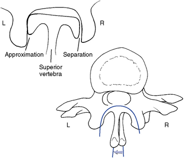
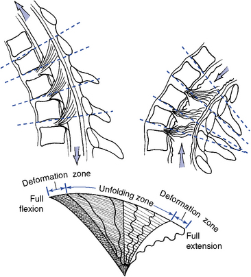
Thoracic flexion and extension combine sagittal plane rotation with slight sagittal plane translation. The degree of combined translation is minimal and uniform throughout the thoracic spine.5 During flexion the articular facets glide apart as the IVD opens posteriorly. During extension, the facet joints and posterior disc approximate (Figure 5-113).
Lateral Flexion
Lateral flexion averages approximately 6 degrees to each side, with the lower two segments averaging 7 to 9 degrees. Lateral flexion is coupled with axial rotation throughout the thoracic spine. This is especially apparent in the upper thoracic spine, where the pattern duplicates that of the cervical spine. The coupling is such that lateral flexion and rotation occur to the same side (e.g., body rotation to the concavity and spinous deviation to the convexity)5,26 (Figure 5-114). In the middle and lower thoracic spine, the coupling is less distinct and may occur in either direction (Figure 5-115).
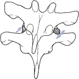
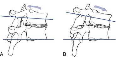
Figure 5-114 Lateral flexion of an upper thoracic segment, showing coupling movement in rotation and lateral flexion to the same side. This pattern is the same as that of the cervical spine.
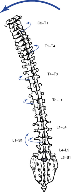
Figure 5-115 Coupled relationship of lateral flexion and axial rotation throughout the spine. The cervical and upper thoracic regions have lateral flexion coupled with ipsilateral rotation, and the lumbar spine and lower thoracic regions have lateral flexion coupled with contralateral rotation.
(From White AA, Panjabi MM: Clinical biomechanics of the spine, ed 2, Philadelphia, 1990, JB Lippincott.)
It is often assumed, however, that the lower thoracic segments have a tendency to follow the coupling pattern of the lumbar spine. The lumbar pattern is opposite that of the cervical and upper thoracic segments and incorporates lateral flexion with coupled axial rotation in the opposite direction27,28 (see Figure 5-115). White and Panjabi5 point out, however, that coupling patterns still remain controversial, and doctors must guard against any strong conclusions.
During lateral flexion, the IVD and facet joints approximate on the side of lateral flexion and separate on the side opposite lateral flexion (see Figure 5-114). In the upper thoracic spine the inferior articular facets also glide medially relative to the superior articular facet on the side of lateral flexion and laterally on the side opposite lateral flexion. This is a result of the strong coupled axial rotation in the upper thoracic spine.
Rotation
Segmental axial rotation averages 8 to 9 degrees in the upper thoracic spine (Figure 5-116). Rotational motion decreases slightly in the middle thoracic spine and drops off dramatically to approximately 2 degrees in the lower two or three thoracic segments.5 The marked decrease in rotational mobility in the lower segments no doubt reflects the transition from coronal plane facets to sagittal plane facets.
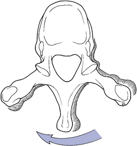
Figure 5-116 Horizontal view, illustrating right rotation of the superior vertebra (light) relative to the inferior vertebra (dark).
Rotational movements in the thoracic spine are also coupl- ed with lateral flexion. In the upper thoracic spine, rotation is coupled with same-side lateral flexion. This leads to MI gliding of the inferior facet relative to the superior facet on the side of trunk rotation and LS gliding of the inferior facet on the side opposite trunk rotation. The coupling is not as marked in the lower segments as it is in the upper segments.6 This may occur because the facets of the lower thoracic spine become more sagittal in their orientation.
Kinetics of the thoracic spine
The same principles of concentric and eccentric muscle activity discussed for the cervical spine apply to the trunk. Nonsegmental muscles can induce movement of the entire thoracic spine or act segmentally. They include the erector spinae, rectus abdominis, quadratus lumborum, and abdominal obliques. The segmental muscles that influence each thoracic motion segment include multifidi, interspinalis, intertransversarii (small in the thoracic segments), and rotatores.
Flexion is initiated by concentric activity of the rectus abdominis and controlled or limited by eccentric activity of the erector spinae. Flexion is further limited by the elastic limits of the myofascial tissue, ligamentum flavum, interspinous ligament, supraspinous ligament, PLL, capsular ligaments, posterior IVD, and bony impact of the vertebral bodies.
Extension is initiated by concentric activity of the erector spinae and controlled or limited by eccentric activity of the rectus abdominis. Extension is mainly limited by the bony impact of the spinous and articular processes, but the ALL, anterior IVD, and elastic limits of myofascial tissue also contribute.
Lateral flexion is initiated by concentric activity of ipsilateral erector spinae and quadratus lumborum and controlled or limited by contralateral eccentric activity of the same muscles. Further limiting of lateral flexion movement occurs through impact of the articular facets, contralateral capsular, ligamentum flavum, intertransverse ligament, and elastic limits of contralateral segmental and nonsegmental muscles.
Rotation is initiated by concentric activity of ipsilateral erector spinae, multifidus, and rotatores and controlled or limited by concentric and eccentric activity of the abdominal obliques and erector spinae. Rotation is further limited by the articular capsules, interspinous ligament, supraspinous ligament, ligamentum flavum, bony impact of the articular facets, and elastic limits of bilateral segmental and nonsegmental muscles.
Functional anatomy and biomechanics of the rib cage
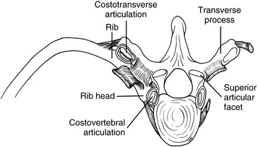
The rib articulations can be divided into two groups, one connecting the heads of the ribs to the vertebral body (costovertebral joints) and one connecting the necks and tubercles of the ribs with the transverse process (costotransverse joints). The costovertebral joints of ribs 1 and 10 to 12 articulate with a single vertebral body. In the remaining costovertebral joints, the rib heads articulate with adjacent vertebral bodies. A facet on the posterior tubercle of the ribs and a corresponding facet on ribs 1 to 10 form the costotransverse articulations. Ribs 11 and 12 do not have costotransverse articulations.
The articulations that are formed between the vertebral and costovertebral bodies and the transverse and costotransverse processes are each tightly secured by ligaments (Figure 5-117). Both of these articulations are true synovial joints. The costotransverse articulation is surrounded by a joint capsule, with further strength from the costotransverse ligaments. The costovertebral articulations have a single capsular ligament surrounding the two demifacet articulations, which are further strengthened by the radiate ligament.
These synovial joints are prone to the same pathologic conditions that affect other synovial joints, including the subluxation and dysfunction complex. Furthermore, the ribs play an integral part in the normal activity of the thoracic functional unit and should be a significant consideration in evaluation for thoracic dysfunction.
Anteriorly, the first seven ribs connect to the sternum directly, and the eighth, ninth, and tenth ribs attach indirectly via the costocartilage (Figure 5-118). The eleventh and twelfth ribs are free floating, with no anterior attachment. The anterior articulations move mainly because of the elastic quality of the costocartilage. Calcification and subsequent decreases in movement can occur with age.
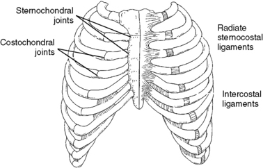
Figure 5-118 Anterior attachments of the ribs to the sternum: 2 to 7 directly and 8 to 10 indirectly via costocartilage.
Movements of the Rib Cage with Spinal Movements
The ribs influence movement of the individual thoracic vertebrae, and the rib cage influences the movement of the entire thoracic spine. With flexion and extension, the ribs move correspondingly with the thoracic spine, resulting in the posterior intercostal spaces opening up with flexion and closing with extension. The entire rib cage must flatten superiorly and inferiorly, increasing the sternal angle, for flexion of the thoracic spine to take place. The converse is true for extension (Figure 5-119). A similar relationship occurs with lateral flexion as the rib cage is depressed on the side of lateral flexion. Furthermore, the lateral intercostal spaces open on the convex side and close on the concave side. With thoracic rotation, the rib angle is accentuated on the side of posterior trunk rotation, and flattening of the rib angle occurs on the side of anterior trunk rotation (Figure 5-120).
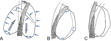
Figure 5-119 The effects of lateral flexion (A), flexion (B), and extension (C) on the shape of the rib cage.
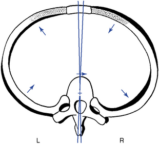
Figure 5-120 The effects of right rotation of a thoracic vertebra on its associated rib, leading to accentuation of the posterior concavity of the rib on the side of vertebral rotation and flattening of the posterior concavity of the rib on the opposite side.
(From Kapandji IA. In: The physiology of the joints, ed 2, vol 3, Edinburgh, 1974, Churchill Livingstone.)
Movements of the Rib Cage with Respiration
Individually and collectively, the ribs undergo two main types of motion during respiration. These movements are commonly referred to as bucket handle and pump handle movements.
Bucket-handle movement increases the transverse diameter of the rib cage by elevating the rib and its costochondral arch (Figure 5-121). Bucket-handle movement is greater in the lower thoracic spine, where the relatively flat tubercular facets of the ribs and corresponding articular facets of the transverse processes allow the rib to ride up and down against the transverse process. The lower ribs may therefore roll around an axis connecting the costovertebral and sternochondral joints. This allows for elevation and depression of the ribs with respiration and a movement that simulates the rolling movement of a bucket handle when it is elevated on its hinges.29
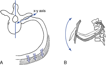
Figure 5-121 Movements of the ribs. A, Axial view of pump-handle movement, with the rib rotating around the x-y axis, elevating the rib in front. B, Lateral view, demonstrating elevation of the rib and anterior-to-posterior expansion of the rib cage. C, Bucket-handle movement, illustrating transverse expansion of the rib cage.
Pump-handle movement increases the A-P diameter of the rib cage. It occurs more in the upper rib cage than in the lower and results from the elevation of the anterior aspect of the rib cage with the upward and forward movement of the sternum. In contrast to the lower ribs, the tubercular facets of the upper ribs are situated in deep cup-shaped sockets on the transverse processes. Therefore, the rib is free to move only along the axis that connects the costovertebral and costotransverse joints. With inspiration, the rib head rolls downward, elevating the anterior end of the rib like the handle of a pump28 (see Figure 5-121).
Kinetics of Respiration
During quiet respiration, thoracic mobility is minimal because the diaphragm is the main muscle of respiration. The intercostal muscles are slightly active to supply tension, and the quadratus lumborum fixes the twelfth rib to provide a stable attachment. However, during forced respiration, the external intercostal muscles become active to elevate the ribs and receive secondary help as needed from the scaleni, pectoralis minor, serratus anterior, and iliocostalis cervicis.
Expiration is usually a passive process resulting from the elastic tension produced in the ribs, costocartilage, and pulmonary parenchyma. Forced expiration is produced by the internal intercostal muscles, which receive secondary help from the abdominal muscles, iliocostalis lumborum, longissimus, and quadratus lumborum. The activity of the expiratory muscles is also used to perform the Valsalva maneuver, increasing intra-abdominal pressure.
Upper rib dysfunction is theorized to be associated with ribs fixated in a superior (flexed) position, as a result of the pull of the iliocostalis cervicis, longissimus cervicis, scalenes, and serratus posterior and superior muscles. Similarly, because of the effects of the longissimus thoracis, iliocostalis lumborum, quadratus lumborum, and serratus posterior and inferior muscles, the lower ribs tend to be pulled and fixated inferiorly. However, the iliocostalis thoracis muscle may produce the opposite movement in each area, depressing the upper ribs and raising the lower ribs.
Functional anatomy and characteristics of the transitional areas
The thoracocervical (C6–T3) and thoracolumbar (T10–L1) segments form a transition between the thoracic spine and the cervical and lumbar regions. Hence, some characteristics or activities are shared by both regions and some are unique to each region.
Thoracocervical Junction (C6–T3)
The notable structural changes in this segment include spinous processes that become more elongated, point caudally, and lose the bifid characteristic of the cervical spine. Furthermore, there are no uncinate processes or transverse foramen. The upper thoracic segments include costotransverse and costovertebral articulations, as well as an increased slope to the articular facets.
Because of the distal attachment of the cervical muscles, including the splenius, longissimus, and semispinalis cervicis, as well as the semispinalis capitis muscles, cervical spine movements involve the upper thoracic spine. The ribs in this area provide stability but also decrease motion. Movements in all directions are decreased between C6 and T3, but the coupled movements in this area are the same as for the typical cervical region (e.g., lateral flexion is coupled with rotation to the same side).
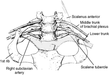
The significance of this area is twofold. First, this area is structurally and functionally related to the neurovascular structures of the upper extremities, because this area forms the thoracic outlet (Figure 5-122). Second, the thoracocervical junction has been deemed a difficult area to apply manipulative therapy. This reputation has been established because of the necessary structural characteristics for a transition from the most mobile area of the spine to the area that is significantly less mobile, as well as the external characteristics of distribution of body fat (dowager hump) and the shoulder and scapular muscles.
Thoracolumbar Junction (T10–L1)
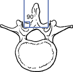
The thoracolumbar transition area is similar to the thoracocervical junction in that it must serve to join an area of greater mobility with one of lesser mobility, as well as change from a primary (kyphotic) curve to a secondary (lordotic) curve. The most significant structural characteristic in this area is the change from the coronal facet plane in the thoracic spine to the sagittal plane facets in the lumbar spine (Figure 5-123). This transition, although typically thought to occur at the T12–L1 segment, has been shown to occur at any of the segments between T10 and L1. Davis30 reported the change was found to occur most commonly at the T11–12 level (Table 5-5).

Figure 5-123 The thoracolumbar transition is characterized by a change in facet planes from coronal to sagittal.
TABLE 5-5 Frequency of Lower Thoracic Segments Demonstrating Transition from Coronal Facets to Sagittal Facets
| Segment | Percentage |
|---|---|
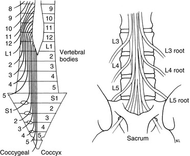
Of further clinical importance is the distribution of the lateral branches of the posterior primary rami of the spinal roots of T12–L2. These nerves form the cluneal nerves and innervate the skin and superficial structures of the upper posterolateral buttock, posterior iliac crest, and groin area (Figure 5-124). Dysfunction within the lower thoracic segments may refer pain into these regions and be mistaken for disorders of the lumbosacral or sacroiliac regions, which also commonly refer pain to these zones. Maigne31 believes this syndrome can account for up to 60% of chronic and acute backache, generally considered the result of lumbar or sacral joint changes.
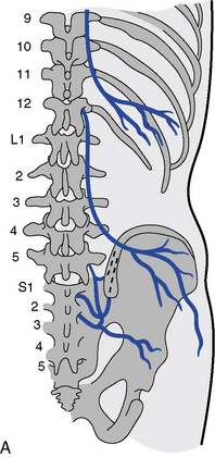
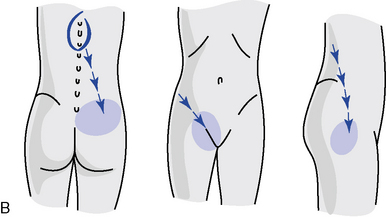
Figure 5-124 The course of the cluneal nerves (A) and possible distribution of pain findings and sensory changes (B).
(A from Grieve GP: Common vertebral joint problems, ed 2, Edinburgh, 1988, Churchill Livingstone. B from Basmajian JV: Manipulation, traction and massage, ed 3, Baltimore, 1985, Williams & Wilkins.)
Evaluation of the thoracic spine
Observation
Before palpation is begun, a visual examination should be made to observe for any deviations in posture or symmetry. Postural syndromes that may predispose the patient to spinal dysfunction and pain are common in the thoracic spine and should not be overlooked. Idiopathic scoliosis has its greatest expression in the thoracic spine, and any noted curvatures should be assessed for flexibility.
Alignment in the coronal plane is evaluated by observing the orientation of the spinous processes, symmetry of paraspinal soft tissues, and contours of the rib cage. The alignment of the shoulders and angles of the scapula should be observed and compared relative to the iliac crests. Sagittal plane alignment is assessed by observing the status of the thoracic curve and noting the position of the gravity line. Orientation of the trunk in the transverse plane is noted by looking at the shoulders and vertebral borders of the scapula for any winging (Figure 5-125).
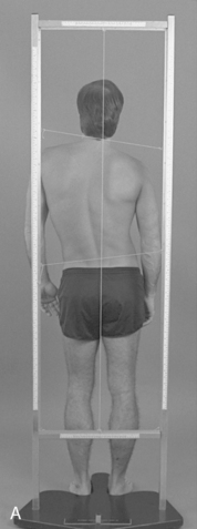
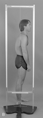
Figure 5-125 Postural evaluation. A, Posterior plumb line, demonstrating shoulder and pelvic unleveling creating a C-shaped scoliosis. B, Lateral plumb line, demonstrating a round back deformity with an anterior shift in the gravitational line.
Global motion of the thoracic spine is typically not separated from lumbar movements. Both are measured and recorded as movements of the entire trunk. However, when desired, regional movements of the thoracic spine may be assessed with the inclinometric measuring methods previously described in Chapter 3 (see Figure 3-10). Table 5-6 presents the average global ROMs for the thoracic spine.
TABLE 5-6 Global Range of Motion for the Thoracic Spine
Static Palpation
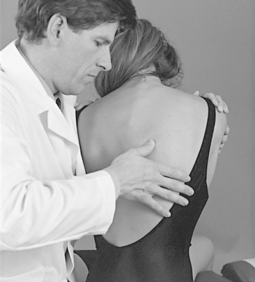
Static palpation of the spine and posterior chest wall is commonly performed with the patient in the prone position. During the evaluation, stand to the side of the patient and accommodate the patient by bending at the knees, hips, and waist. Palpation typically begins with an assessment of superficial temperature and sensitivity, followed by the assessment of consistency and mobility of the dermal layer and muscular layer. Palpation of bony landmarks incorporates a scanning assessment of contour, tenderness, and alignment of the spinous processes, transverse processes, rib angles, interspinous spaces, and intercostal spaces. In addition, the alignment of the scapula and its borders and angles is customarily included in the evaluation of the thoracic spine.
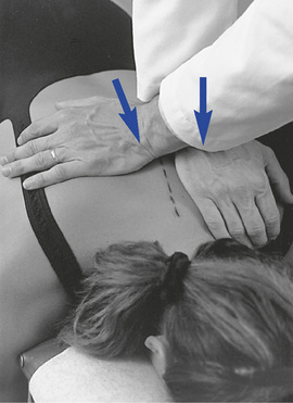
Potential tenderness and alignment of the spinous processes, interspinous spaces, and transverse processes are assessed with unilateral or bilateral fingertip contacts (Figures 5-126 and 5-127). Paraspinal muscle tone is evaluated by applying bilateral contacts with the palmar surfaces of the fingers or thumbs to explore for areas of tenderness and altered muscle tone and texture (see Figure 5-127).
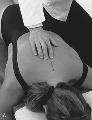
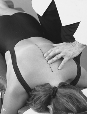
Figure 5-126 Palpation of rotational alignment and sensitivity of thoracic spinous processes (A) and interspinous spaces and sensitivity (B).
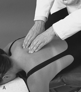
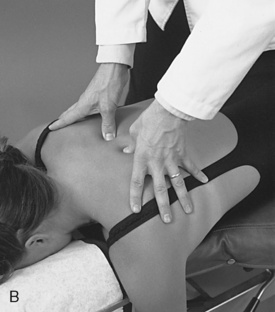
Figure 5-127 Palpation of transverse process alignment and paraspinal soft tissue tone, texture, and sensitivity using fingertip contacts (A) and thumb contacts (B).
Rib alignment and tenderness is assessed by palpating along the rib angles with the fingertips or thumb. Palpation may be conducted with the patient in the sitting or prone position. The sitting evaluation has the advantage of being able to induce trunk rotation to accentuate the ribs for palpation. When rib alignment is assessed in the sitting position, the patient is asked to cross the arms over the chest and flex slightly forward. The doctor then sits or stands beside the patient and rotates the patient forward on the side to be palpated (Figure 5-128).
The rib angles should be uniform in prominence and not tender. A tender or distinctly palpable lump that stands out in relation to the adjacent ribs may indicate rib dysfunction. Take care to differentiate a prominent rib from a myofascial trigger point (the former is bony and immobile; the latter softer and more mobile). The pain associated with costotransverse dysfunction is often accentuated with respiration and may radiate to the anterior chest wall. Dysfunction of the costosternal junction may also be present with or without posterior dysfunction. Evaluate the anterior chest wall for myofascial or joint dysfunction when the patient complains of pain of the posterior or anterior chest wall.
Motion Palpation
Joint Play
The thoracic spine should be scanned for sites of painful or abnormal JP with the patient sitting or prone. Areas of elicited abnormality should be further assessed with counter-rotational JP procedures. With the patient in the prone position, P-A glide is assessed by establishing contacts over the spinous process or bilaterally over the transverse processes. P-A pressure is gradually applied and a springing motion is created. During P-A JP assessment, a subtle pain-free gliding and recoil should be felt at each level tested (Figures 5-129 and 5-130).
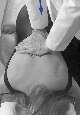
 Figure 5-129 Prone midthoracic joint play evaluation, using bilateral fingertip contacts over the transverse processes and applying a posterior-to-anterior vector of force.
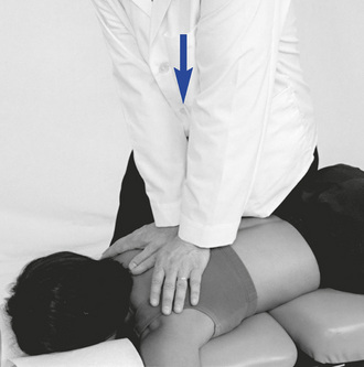
 Figure 5-130 Prone midthoracic joint play evaluation, using bilateral thenar contacts over the transverse processes and applying a posterior-to-anterior vector of force.
To further isolate the specific level of pain and possible dysfunction, counter-rotational JP and provocation testing may be applied. To perform this procedure, place thumbs on opposing sides of adjacent spinous processes and apply springing pressure toward the midline (Figure 5-131). This procedure is less giving than A-P glide, and a perceptible decrease in movement is encountered when pressure is applied to adjacent vertebrae. Pain elicited at one level and not at adjacent levels helps localize sites of possible dysfunction.
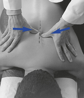
 Figure 5-131 Counter-rotational joint play evaluation for left rotational movement of T7 relative to T8. Opposing forces are directed toward the midline through a contact established on the right side of the T8 and the left side of the T7 spinous process.
If desired, this procedure may be performed with the contacts located over the transverse processes instead of the spinous processes. Precise location of landmarks is more difficult with this method, but it may provide an acceptable alternative in circumstances in which the patient’s spinous processes are tender to light palpation (Figure 5-132).
Segmental Motion Palpation and End Play
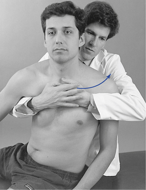
Movement is typically evaluated with the patient in the sitting position, with arms flexed and folded across the chest so that the hands can grasp the opposing shoulders. The doctor’s position may be sitting behind or standing beside the patient; the standing position is usually preferred when the upper thoracic segments are evaluated. Movement is controlled through contacts on the patient’s shoulders for the middle and lower thoracic segments or on the crown of the patient’s head when the upper thoracic segments are evaluated (Figure 5-133). IH contacts on the patient’s head are to be avoided in patients with cervical complaints.
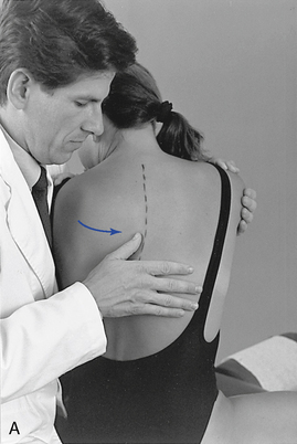
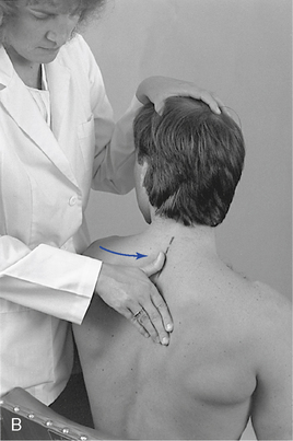
 Figure 5-133 Palpation of left rotational movement at the T7–8 level (A) and the T2–3 level (B), using a thumb contact across the left interspinous space.
Rotation
The segmental contact is established against the lateral surface of the adjacent spinous process on the side of induced rotation. The palpating thumb is placed so that the pad spans the interspinous space. The support hand reaches around the front of the patient and grasps the opposite flexed arm or shoulder and rotates the patient’s trunk toward the side of contact (see Figure 5-133). During normal rotation, the superior spinous process should be palpated, rotating away from the spinous process below. Movement should occur in the direction of trunk rotation. If separation is not noted and adjacent spinous processes move together, segmental restriction should be suspected.
To assess end play, additional overpressure is applied through the contact and IH at the end of passive motion. Firm elastic but giving motion should be encountered. Contacts may be established against the superior spinous process on the side of induced rotation (see Figure 5-133) or over the transverse process and posterior joint on the side opposite the induced rotation (Figure 5-134).
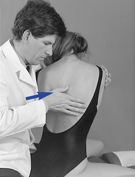
 Figure 5-134
Lateral Flexion
To assess lateral flexion, a segmental contact against the lateral surface of the adjacent spinous processes is established on the side of induced lateral flexion. The doctor either sits or stands behind the patient toward the side of induced lateral flexion. If a sitting position is selected, movement is guided by placing the forearm across the patient’s shoulders (Figure 5-135). In the standing position, movement is directed by placing the doctor’s hand on the patient’s shoulder on the side of induced lateral flexion (Figure 5-136). In the lower thoracic spine, slight patient flexion is produced to accentuate the spinous process and reduce coupled rotation.
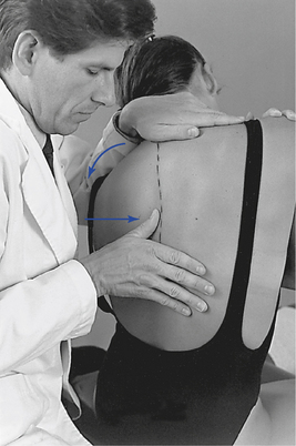
 Figure 5-135 Palpation of left lateral flexion movement at T6–7, using a thumb contact across the left T6–7 interspace, with the doctor seated.
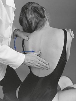
 Figure 5-136
Movement is induced by asking the patient to bend to the side as downward pressure is applied through the indifferent arm. As bending is being actively produced, medial pressure is applied through the contact hand to help accentuate the bending at the site of palpation. The indifferent arm and contact arm work together to isolate the site of lateral flexion by adjusting the amount of applied downward pressure and tilting of the patient. During this movement, the spinous process should be felt to shift toward the opposite side (convex side) while the spine bends smoothly around the contact point (CP). End play is evaluated by applying additional overpressure at the end ROM.
Flexion and Extension
The segmental contacts are established over the interspinous spaces with the doctor’s fingertips or thumb. When flexion and extension in the upper thoracic spine are evaluated, movement is guided by placing the IH on the crown of the patient’s head (Figure 5-137).
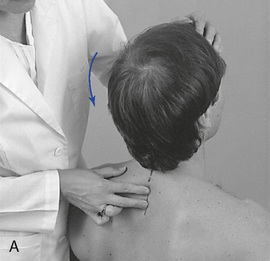
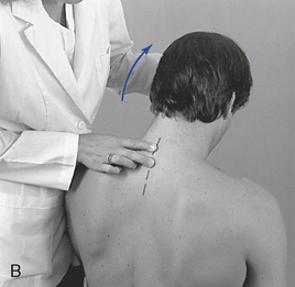
 Figure 5-137 Palpation of extension movement (A) and flexion movement (B) in the upper thoracic spine, using fingertip contacts in the interspinous spaces.
When evaluating flexion or extension in the middle to lower thoracic segments, ask the patient to overlap or interlace his or her fingers behind the neck. To evaluate flexion, place your indifferent forearm across the patient’s shoulder, or grasp the patient’s flexed elbows to help guide movement. To evaluate extension, place your forearm beneath the patient’s flexed arms and apply a lifting action to assist in the development of extension (Figure 5-138). To assess motion, actively or passively flex and extend the spine. Take care to place the apex of bending at the level of palpation. During flexion, the interspinous spaces should open symmetrically, and during extension, they should approximate.
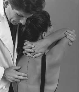
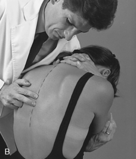
 Figure 5-138 Palpation of extension movement (A) and flexion movement (B) in the middle thoracic spine, using fingertip contacts in the interspinous spaces.
Flexion end play is assessed by maintaining palpatory contact with the inferior aspect of the superior spinous process while gentle downward pressure is applied through a forearm contact on the patient’s shoulders. Extension end play is evaluated by pushing anteriorly after full extension has been reached. Extension end play is inhibited by the impact of the spinous processes and has a more rigid quality than flexion, lateral flexion, or rotation.
Rib Motion Palpation
Ribs 3 to 12
The evaluation of rib mobility incorporates an ass-essment of bucket-handle movement and costotransverse end play. End play is assessed by placing the patient in the sitting position and inducing slight flexion, lateral flexion, and rotation of the patient forward on the side of palpation. The palpation contact is established with the doctor’s thumb or fingertips over the rib angle, just lateral to costotransverse articulation. The doctor reaches around with the nonpalpating hand to grasp the patient’s shoulder and induce rotation. The patient is rotated and the rib is stressed posteriorly to anteriorly at the end of rotation (Figure 5-139). A rib that remains distinctly prominent and provides firm resistance relative to adjacent segments indicates rib dysfunction.
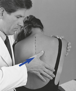
 Figure 5-139 Palpation of posterior-to-anterior end play of the right T7 rib articulation, using a thumb contact over the right T7 rib angle.
To assess bucket-handle motion, the doctor places his or her fingertips in the intercostal spaces at the midaxillary line. The doctor’s indifferent arm is placed across the patient’s shoulders, and the patient is laterally flexed toward and away from the side of contact (Figure 5-140). The intercostal spaces should open with lateral flexion away from and close with lateral flexion toward the contacts. Absence of symmetric opening and closing may indicate dysfunction at the costotransverse joint or stiffness in the intercostal soft tissues.
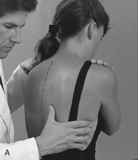
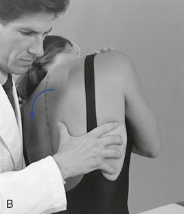
 Figure 5-140
Ribs 1 and 2
To evaluate mobility of the upper two ribs, place the patient in a sitting position and contact the PS portion of the first or second rib with the fingertips. The IH grasps the crown of the patient’s head, rotates it away from the side being palpated, and laterally flexes and extends the head toward the side being palpated (Figure 5-141). During this motion the rib should drop inferiorly and seem to disappear. Dysfunction should be suspected if the rib remains prominent and immobile during the passive movements of the head.
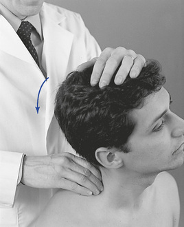
 Figure 5-141
Anterior Rib Dysfunction
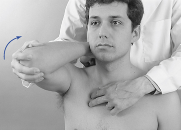
To evaluate movement of the costosternal joints and anterior intercostal spaces, place the patient in the sitting position and stand behind the patient while contacting the intercostal spaces just lateral to the sternum. Take care to avoid contact with the breasts of female patients. Flex the patient’s elbow and shoulder on the side of palpation and grasp the elbow (Figure 5-142). Move the patient’s flexed arm into further flexion and palpate for opening of the intercostal spaces (e.g., the superior rib should move cranially in relation to the inferior rib).
Overview of thoracic spine adjustments
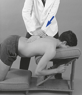
Prone Adjustments
Prone thoracic adjustments are characteristically direct short-level methods (Figure 5-143). They have the advantage of providing effective and specific access to points of contact while allowing for positions that maximize posterior to anterior incorporation of the doctor’s body weight in directing and delivering adjustive thrusts.
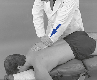
 Figure 5-143
Although they are commonly delivered with the patient in a relatively neutral position, it is possible to modify prone positioning to induce positions that assist in the development of preadjustive tension and the desired movement. Elevation of the thoracolumbar section of an articulating table or Dutchman roll may be used to develop segmental flexion, and the thoracolumbar section may be lowered to induce extension. Placing the patient on his or her forearms on an adjustive bench can also be used to induce more preadjustive segmental extension. Lateral flexion may be induced by bending the patient to the side or by side-bending a flexion table. Rotation of the trunk is not practical on most adjusting tables, although some rotation may be induced with rotation of the pelvic section of flexion tables.
After the patient is appropriately positioned and the contacts are established, the doctor reduces articular slack by transferring additional body weight into the contact. At tension, the adjustive thrust may be generated solely through the arms but more frequently incorporates a combined body-drop and arm thrust.
Knee-Chest Adjustments
Knee-chest adjustments are similar to prone thoracic adjustments (Figure 5-144). In most cases, the only difference is the modification in positioning the patient must undergo on the knee-chest table. Knee-chest adjustments may be applied to any region of the thoracic spine and under many of the same circumstances as prone thoracic adjustments. However, they are probably most effectively applied in the treatment of lower thoracic extension restrictions (flexion malpositions). The knee-chest table does not restrict thoracolumbar extension and therefore allows the doctor to maximize movement into extension. Although it does provide for maximal extension, it also makes the patient vulnerable to hyperextension. Consequently, the doctor must be skilled in this procedure and apply it only with shallow, gentle, nonrecoil thrusts.
Sitting Adjustments
Sitting thoracic adjustments afford the doctor the opportunity to modify patient position in the development of preadjustive tension (Figure 5-145). They are typically applied as assisted adjustments with the adjustive contact established on the superior vertebra. The IH contacts the anterior forearm to assist in the development of appropriate trunk rotation. At tension, both hands thrust to induce motion in the direction of restriction to induce distraction at the motion segments below the level of contact. They are most commonly applied for rotational restrictions in the middle to lower thoracic spine but may be applied for combined rotation and lateral flexion restrictions.
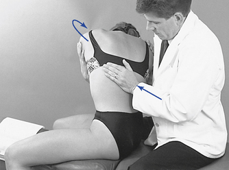
 Figure 5-145
Supine Adjustments
The effectiveness of supine adjustive techniques is a controversial topic within chiropractic. A number of chiropractic colleges have limited or no instruction in supine techniques, and a significant percentage of practicing chiropractors also object to their application. The basis for this position appears to be related to the contention that supine techniques are less specific and therefore less effective. Unfortunately, this contention has led to a lack of investigation and understanding of the appropriate application of supine techniques. We believe supine techniques should not be dismissed out of hand. They can be effective if applied in the proper circumstances, and they should be considered for incorporation in the management of thoracic dysfunction. Supine techniques allow the doctor the opportunity to significantly modify patient position. Predisposing patients into the direction of desired movement restriction may be helpful in producing the desired adjustive movement and effect. Supine techniques also use the patient’s body weight to assist the doctor in developing preadjustive tension and adjustive force. Their major disadvantage is access to posterior spinal CPs and the close physical contact that is generally required between the doctor and patient.
One of the major distinctions between prone and supine adjustive techniques is the activity of the posterior spinal contacts. In supine techniques, the posterior contact is customarily passive and provides a fulcrum point for localizing the site of preadjustive tension and reactive adjustive force.
The adjustive impulse in supine technique is generated by thrusting with the weight of the doctor’s torso through the patient toward the posterior contact (Figure 5-146). The adjustive thrust accelerates the patient toward the posterior contact and generates a force back toward the patient’s spine as the posterior contact meets the firm resistance of the adjustive table.
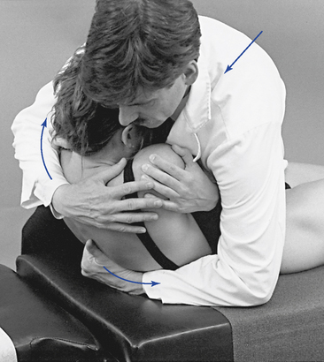
 Figure 5-146
Supine adjustive techniques also involve a potential component of axial traction applied during the development of preadjustive tension and delivery of an adjustive impulse. Long-axis traction may aid in the distraction of the posterior joints and is helpful in minimizing unnecessary compression to the patient’s rib cage. The doctor generates this force by incorporating a small headward (I-S) orientation and movement as he or she develops preadjustive tension.
The positions of the posterior hand contacts vary depending on the area of application and the dysfunction being treated. The optional hand positions (Figure 5-147) and the appropriate application of each are discussed under each specific adjustment. When applying a bilateral transverse contact, the spinous processes rest in the midline of the doctor’s cupped hand or clenched fist as the thenar and phalanxes contact each side of the patient’s spine over the transverse process. Care must be taken to ensure the contacts are established medial to the rib angles and equally balanced. When developing contacts in the lower thoracic spine, it is important to place the hand in a more vertical position to bridge the distance between the table and the patient.
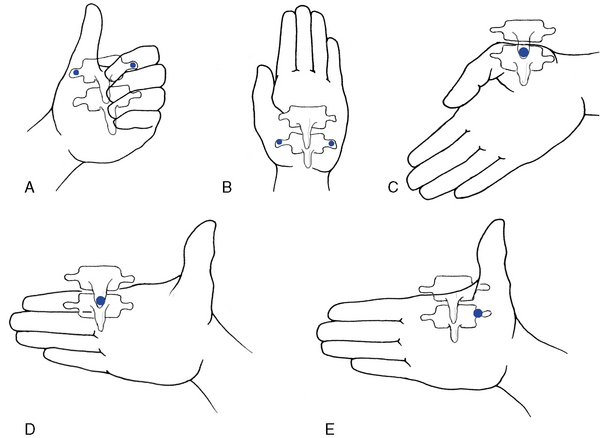
Figure 5-147 Optional hand positions for supine thoracic adjusting. A, Clenched fist, where the thenar and index contacts are established bilaterally over the vertebral transverse processes. B, Open palm, where the thenar and hypothenar contacts are established bilaterally over the vertebral transverse processes. C, Open palm, where the thenar contact is established against the inferior tip of the spinous process. D, Open palm, where the index contact is established against the inferior tip of the spinous process. E, Open palm, where the thenar contact is unilaterally established over the vertebral transverse process.
Supine adjustive techniques also allow for a variety of optional patient arm placements (Figure 5-148). The positioning of the patient’s arms is mainly a matter of doctor discretion. However, when crossing the patient’s arms across the chest, it is important to consider both patient and doctor comfort. To reduce the stress to the patient’s anterior chest or breasts, a small sternal roll may be placed between the patient’s crossed arms. To lessen the pressure against the doctor’s upper abdomen or chest, a rectangular pillow may be placed between the patient’s crossed arms and the doctor.
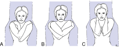
Figure 5-148 Optional patient arm positions in the supine thoracic adjustment. A, Right arm crossed over left. B, Crossed-arm position to separate the scapula and decrease posterior-to-anterior depth of torso. C, Pump-handle position.
When using crossed-arm positions in large patients, it is helpful to cross the arms in a manner that decreases the combined A-P diameter of the patient’s thorax. Positions that cross only one arm over the chest or cross the opposing forearm beneath the other (Figure 5-148, B) decrease the A-P distance. Positions that interlace crossed arms (Figure 5-148, A) tend to produce more padding for the patient’s anterior chest but tend to increase the A-P distance from the patient’s forearms to the table.
Standing Adjustments
Standing thoracic adjustments use the same mechanical principles as supine thoracic adjustments (Figure 5-149). More significantly, they provide positions that allow the doctor to use the strength of his or her legs in developing preadjustive tension and the adjustive impulse. When applying standing methods, it is important to direct the adjustive force in an A-P and I-S direction to avoid uncomfortable compression of the patient’s upper abdomen. Standing adjustments may be difficult to perform in acute patients who cannot withstand weight-bearing and are impractical in situations in which there are large discrepancies in height between doctor and patient.
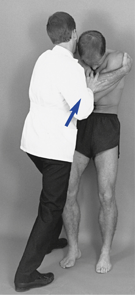
 Figure 5-149
Rotational Adjustments
Rotational dysfunction of the thoracic spine may result from decreased mobility in the posterior joints and associated soft tissues on one side or both sides of the involved motion segment (Figure 5-150). The side and site of fixation are assessed by comparing each side for subjective and palpatory pain, soft tissue texture asymmetry, and end-play quality.
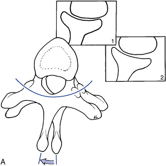
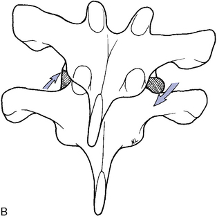
Figure 5-150 A, Transverse view of right rotation at T5–6, showing gliding movement of the left articulation (Box 1) and gliding and end-play gapping of the right articulation (Box 2). B, Coronal view, illustrating the coupled right lateral flexion associated with right rotation at T5–6, with superior glide of the left T5 articular surface relative to T6 and inferior glide of the right T5 articular surface relative to T6.
Rotational dysfunction may be treated with prone, supine, standing, or sitting adjustive methods. Prone methods most commonly use assisted contacts, but methods that apply counterthrust contacts are also frequently used. Resisted methods are not commonly applied in prone patient positions.
Assisted methods are applied with the doctor establishing contacts over the transverse process or spinous process of the superior segments (Figures 5-151 and 5-152). Resisted methods use contacts applied over the transverse or spinous process of the inferior segments (Figures 5-153 and 5-154). Counterthrust methods use contacts applied over the adjacent transverse process (Figure 5-155). When using bilateral contacts, the doctor has the option of making one hand active and one hand passive or of making both hands active. Counterthrust methods use active thrusts through both CPs. Counterstabilizing methods use one active hand and one countersupporting and nonthrusting contact.
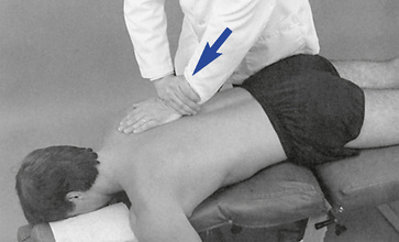
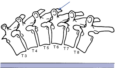
 Figure 5-151 Hypothenar transverse contact applied to the right transverse process of T6 to induce left rotation or left lateral flexion of the T6–7 motion segment.
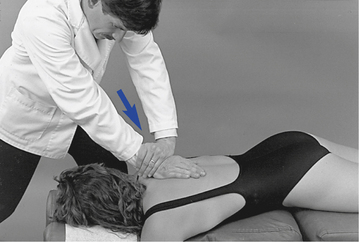
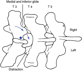
 Figure 5-152 Unilateral hypothenar contact applied to the right lateral surface of the T3 spinous process (dot) to induce right rotation or right lateral flexion in the T3–4 motion segment. Arrows indicate direction of adjustive thrust.
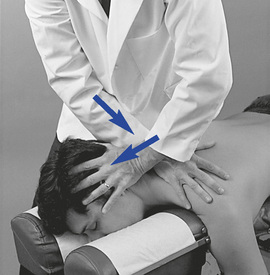
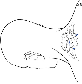
 Figure 5-153 Resisted method. Hypothenar contact applied to the left transverse process of T2 (dot) or right spinous process of T2 (x), resisted by counter-rotation and lateral flexion of the segments above. Depicted is a procedure for treatment of a left rotation and/or coupled right lateral flexion restriction at T1–2 with distraction of the left T1–2 articulation. Arrows indicate the direction of motion induced during the application of the procedure.
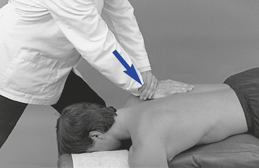
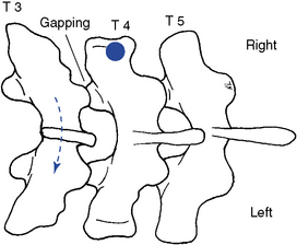
Figure 5-154 Resisted unilateral hypothenar contact applied to the right transverse process of T4 (dot) to induce gapping in the right T3–4 articulation. The adjustive force (solid arrow) is directed posteriorly. The broken arrow and position of T3 illustrates the relative movement generated between T3 and T4. It does not reflect any starting malpositioned state of T3. This procedure is not commonly applied.
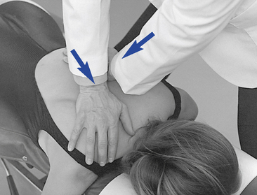
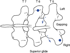
 Figure 5-155 Crossed bilateral contacts applied to the T5–6 motion segment to induce left rotation. The left hypothenar contact is established over the left transverse process of T6 (dot) and the right thenar contact is established over the right transverse process of T5. Solid arrows illustrated in the picture indicate direction of adjustive force, and the broken arrows illustrated in the diagram indicate the motion induced in the T5–6 motion segment during the application of the procedure.
When rotational dysfunction is treated, it may be more effective to use bilateral contacts on adjacent vertebral segments as compared with unilateral contacts (see Figure 5-155. This should help isolate the adjustive forces to the site of fixation and reduce tension to adjacent joints.
Prone resisted adjustive methods are commonly applied in the upper thoracic spine (C7–T2). During the application of these methods, the cervical spine is slightly laterally flexed away from and rotated toward the direction of restriction (see Figure 5-153).
When applying resisted methods with transverse process contacts, the contacts are established on the side of rotational restriction. When applying resisted methods with spinous processes contacts, the contacts are established on the side opposite the rotational restriction (see Figure 5-153). The inferior vertebral contact applies counterpressure to induce pretension in the joints superior to the level of contact. At tension, the adjustive thrust is delivered through the contact hand as the IH applies countertraction headward. For example, if the doctor is treating a restriction in left rotation at the T1–2 motion segment with a resisted approach, the contact is established over the left transverse process of T2 or the right lateral surface of the T2 spinous process. The superior segments and head are rotated into left rotation, and maximal tension should be generated in the motion segments superior to the point of adjustive contact (T2) (see Figure 5-153).
When using sitting patient positions in the treatment of rotational dysfunction, it is customary to use assisted methods to aid in the development of trunk rotation. In all assisted methods, the adjustive contact is established over the superior vertebra, and the thrust is directed to induce distraction in the joint below the contact (Figure 5-156).
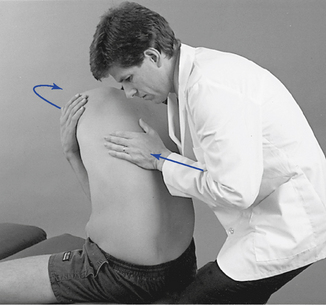
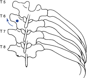
 Figure 5-156 Unilateral hypothenar contact applied to the left T6 transverse process (dot) to induce right rotation or right lateral flexion.
When applying supine adjustments in the treatment of rotational dysfunction, either assisted or resisted methods may be used. Assisted methods are applied to induce rotation at the segments below the level of contact. Maintaining the patient in a position of segmental flexion may assist the doctor in distracting the joints below the level of contact (Figure 5-157). With resisted methods, the doctor establishes a thenar contact over the transverse process of the vertebra inferior to the level of dysfunction. The contact is established on the side of fixation with the patient’s shoulders rotated toward the side of contact (Figure 5-158). The contact provides a block and fulcrum point to induce rotation in the joints above the contact. The adjustive thrust is directed through the doctor’s trunk toward the table to induce rotation and gapping in the direction of trunk rotation at the segments above the contact level (see Figure 5-158).
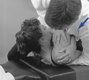
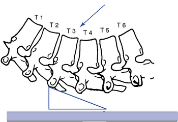
 Figure 5-157 Assisted method. Unilateral thenar contact applied to the right transverse process of T3 to induce left rotation or left lateral flexion in the T3–4 motion segment. Wedge illustrates the placement of the hand and thenar, and arrow illustrates the direction of adjustive vector through the doctor’s trunk.
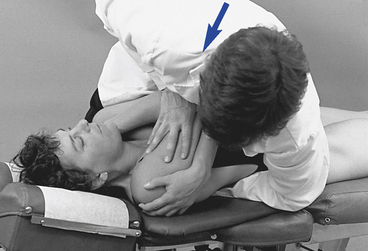
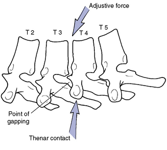
 Figure 5-158
Lateral Flexion Adjustments
Lateral flexion dysfunction in the thoracic spine may result from a loss of inferior glide and approximation of the facet joints on the side of lateral flexion restriction or loss of opening on the side opposite the lateral flexion restriction (Figure 5-159). When treating lateral flexion restrictions in the prone position, the doctor may establish a unilateral transverse process contact on the superior vertebra on the side opposite the lateral flexion restriction and thrust P-A and superiorly (Figure 5-160) or on the side of lateral flexion restriction and thrust P-A and inferiorly. Lateral flexion dysfunction may also be treated in the prone position with bilateral transverse contacts. When applying this method, the contacts are established on each side of the superior vertebra. The contact hand on the side of lateral flexion restriction drives anteriorly and inferiorly to induce inferior glide while the other drives anteriorly and superiorly to induce superior glide (Figure 5-161).
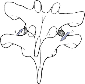
Figure 5-159 Coronal view of right lateral flexion showing gliding distraction of the left articular surfaces (1) and gliding approximation of the right articular surfaces (2).
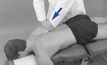
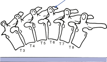
 Figure 5-160 Hypothenar transverse contact applied to the right transverse process of T6 to induce right lateral flexion of the T6–T7 motion segment.
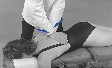
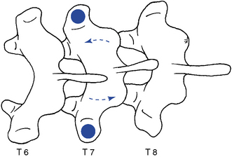
 Figure 5-161 Bilateral hypothenar contacts applied to the transverse processes of T7 (dots) to induce left lateral flexion at the T7–8 joint.
When using spinous contacts in the prone position (Figure 5-152), the doctor establishes the contacts on the side of lateral flexion restriction. The thrust is delivered anteriorly and medially toward the midline to induce closure of the facets and disc on the side of lateral flexion restriction.
In prone adjustive methods, with the patient positioned in a neutral position, it is unlikely that the doctor’s hand contacts can establish enough tension (grip) with the underlying structures to induce segmental lateral flexion.32 This suggests that using approaches and patient positions capable of prestressing the spine in the direction of desired spinal movement may be preferable.
In prone upper thoracic spine adjustments, the doctor may choose to use a resisted method. With resisted methods the contact is established on the lower thoracic segment, and preadjustive tension is developed by tractioning the cervical segments on the side of adjustive contact (Figure 5-153). At tension, an adjustive thrust is directed anteroinferiorly with the contact hand as countertension is directed through the indifferent contact. This method is designed to separate and distract the joints above the SCP.
If lateral flexion dysfunction is treated in the sitting, standing, or supine position, assisted patient positions are commonly used. The contacts are established on the transverse process of the superior vertebra on the side opposite the lateral flexion restriction, and the patient is laterally flexed in the direction of restriction. In the sitting position, the thrust is directed anteriorly and superiorly (Figure 5-156); in the supine and standing positions, the thrust is directed through the trunk posteriorly and superiorly. In the supine and standing positions, the patient must be maintained in a flexed position to assist in the distraction of the involved joint (Figure 5-157).
Flexion and Extension Adjustments
Flexion and extension dysfunction may be treated with prone, knee-chest, supine, or standing patient positions. Flexion restrictions produce a loss of gliding distraction in the posterior joints, and extension restrictions produce a loss of inferior glide and approximation in the posterior joints (Figure 5-162).
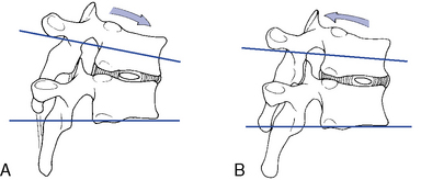
Figure 5-162 Sagittal view of the middle thoracic segments in flexion with separation and gliding distraction of the facet joints (A) and extension with gliding approximation of the facet joints (B).
To induce flexion in the prone position and distraction of the posterior joints, the doctor commonly establishes contacts against the transverse processes or spinous process of the superior vertebra and directs an adjustive VEC anteriorly and superiorly (Figure 5-163). In the upper or lower thoracic spine, where superior vertebral contacts may be hard to maintain, the doctor may contact the inferior vertebra of the involved motion segment. With this method, the doctor faces caudally, and the adjustive thrust is directed anteroinferiorly to induce separation superior to the contact (Figure 5-164). In prone adjustive methods, with the patient positioned in a neutral position, it is unlikely that the doctor’s hand contacts can establish enough tension (grip) with the underlying structures to induce segmental flexion.32 This suggests that using approaches and patient positions capable of prestressing the spine in the direction of desired spinal movement may be preferable.
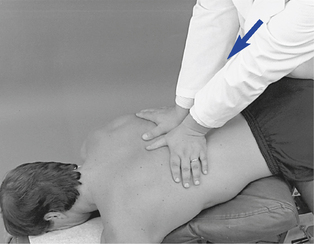
 Figure 5-163
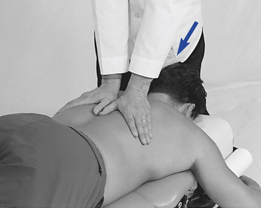
Figure 5-164 Assisted bilateral thenar contacts applied to T8 to induce flexion of the T7–8 motion segment.
Supine adjustive postures may be more effective in the treatment of flexion restrictions by allowing for the production and maintenance of spinal flexion. The adjustive contacts may be established on either the superior or inferior vertebra of the involved motion segment while the patient is maintained in a position of segmental flexion. Superior (assisted) vertebral contacts are designed to distract the motion segments inferior to the level of the contact hand (Figure 5-165). Inferior vertebral contacts are designed to distract the motion segments superior to the level of contact.
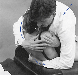
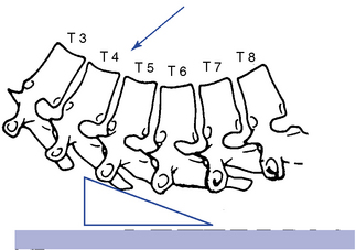
 Figure 5-165 Assisted method, with bilateral contacts established on the transverse processes of T5 to induce flexion at the T5–6 motion segment.
With superior vertebral contacts, the doctor establishes contacts with an I-S tissue pull, and an S-I tissue pull is used with inferior vertebral contacts. To develop preadjustive tension, the doctor leans into the patient directing the patient’s trunk into the posterior contacts. At tension, the adjustive thrust is delivered posteriorly through the doctor’s torso toward the site of contact (see Figure 5-165).
To induce extension in the prone or knee-chest positions, the doctor establishes contacts over the transverse process or spinous process of the superior vertebra of the dysfunctional joint. The doctor’s center of gravity is commonly positioned over the contacts with the adjustive VEC directed anteriorly to induce extension (Figure 5-166). In the upper or lower thoracic spine the doctor may face caudally and direct the VEC slightly inferiorly to assist in the development of tension and extension.
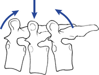
Figure 5-166 Bilateral thenar contacts applied over the T7 transverse processes (center arrow), with the adjustive vector directed posteriorly to anteriorly. The posterior-to-anterior thrust generates anterior translation of T7 and extension of T7–8 and T6–7 motion segments.
To induce extension in the supine or standing patient positions, the contacts are typically established over the inferior vertebral segments. The joint to be adjusted is bent into extension over the top of the posterior contact, and the doctor thrusts posteriorly, using body weight to induce distraction in the joints above the contact (Figure 5-167). This adjustment should also incorporate some long-axis distraction to help decompress the joint. Straight P-A thrusts may unnecessarily compress the rib cage.
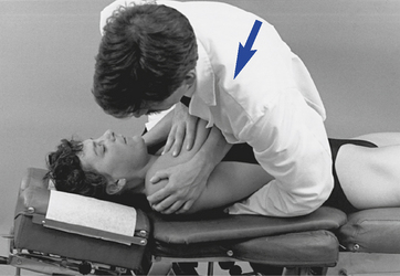
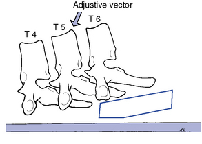
 Figure 5-167
Overview of rib adjustments
Prone Rib Adjustments
Prone rib adjustments are usually direct short-lever or combined short- and long-lever methods, incorporating specific but broader contacts. They are delivered with the patient in a relatively neutral position; the doctor’s body weight is used in the development of preadjustive tension. Broader contacts are used so that the thrust does not focus the force of the adjustment over a small area of the rib. The rib is more fragile than the vertebral TPs and is therefore more easily injured.
Sitting Rib Adjustments
Sitting rib adjustments, like sitting thoracic adjustments, afford the doctor the opportunity to induce rotation or lateral flexion in the development of preadjustive tension. The adjustive contacts are established on the rib angle just lateral to the transverse process and are applied as assisted adjustments. The IH contacts the anterior forearm to assist in the development of appropriate trunk rotation. At tension, the doctor thrusts to induce distraction at the costotransverse articulation.
Supine Rib Adjustments
Supine rib adjustments can be very effective in the treatment of rib dysfunction and should be considered for incorporation in the management of rib dysfunction. The adjustive impulse in supine rib techniques is generated by thrusting with the weight of the doctor’s torso through the patient toward the posterior contact. The posterior contact is established just medial to the rib angle with the doctor’s thenar process. The positioning of the patient’s arms is mainly a matter of doctor discretion and patient comfort.
Gapping Adjustments of the Costotransverse Articulation
The primary adjustive movement generated at the costotransverse articulation is likely to be one of gapping. This movement is generated as the rib is distracted from its transverse process articulation. This movement is most effectively produced by applying a P-A force against the rib lateral to the transverse process (Figure 5-168).
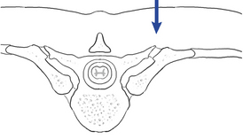
Figure 5-168 Illustration of gapping at the costotransverse articulation induced by a posterior-to-anterior adjustive force.
To induce costotransverse gapping in the prone position, the doctor establishes a contact over the posterior aspect of the rib angle just lateral to the transverse process. The adjustive VEC is directed posteriorly to anteriorly to depress the rib anteriorly and induce separation at the costotransverse articulation (see Figure 5-192).
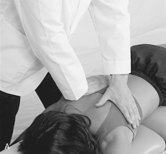
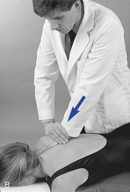
 Figure 5-192 A, Hypothenar contact applied to the superior margin of the right sixth rib angle to induce gapping of the right sixth costotransverse articulation. Crossed contact applies gentle countersupport without imparting a thrust. B, Hypothenar contact applied to the inferior margin of the right fourth rib angle to induce gapping of the right fourth costotransverse articulation.
To induce gapping in the supine position, the contact is established at the same location, and the doctor accelerates his or her body weight toward the posterior contact (see Figure 5-187). The acceleration of the doctor’s body weight through the patient’s torso is designed to accelerate the patient into the doctor’s posterior contact. The doctor’s posterior contact, which is fixed against the adjusting table, produces a reactive force anteriorly against the rib angle, producing gapping at the costotransverse articulation.
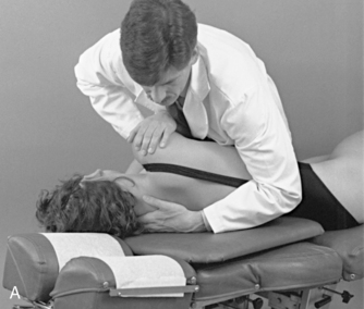
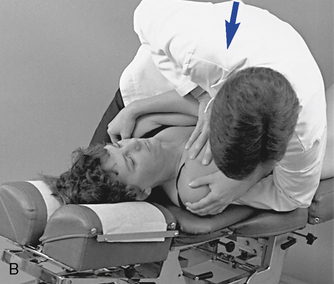
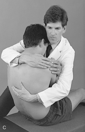
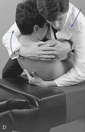
 Figure 5-187 Supine rib adjustment, using a thenar contact over the right third rib starting in the supine position (A) and an anterior-to-posterior thrust through the doctor’s torso to induce gapping in the right costotransverse articulation (B). C, Thenar contact applied over the inferior margin of the right eighth rib, starting in the seated position. D, Anterior-to-posterior thrust through the doctor’s torso to induce gapping in the right eighth costotransverse articulation.
Bucket-Handle Rib Adjustments
The side-posture position is most effective for inducing bucket-handle movements. The patient lies over a roll to develop preadjustive tension, and a contact is applied in the intercostal space against the superior or inferior aspect of the rib in the midaxillary line. With the doctor facing cephalad, the contacted rib is elevated; with the doctor facing caudal, the rib is depressed (see Figure 5-195).
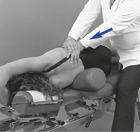
 Figure 5-195
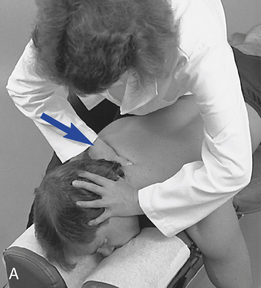
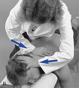
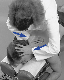
 Figure 5-169
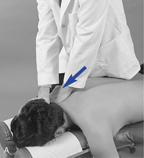
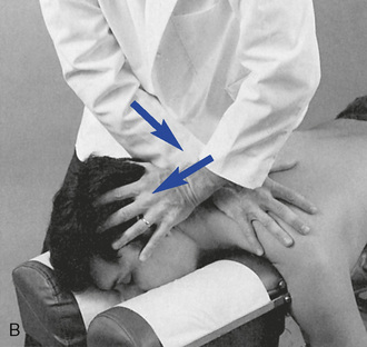
 Figure 5-170
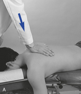
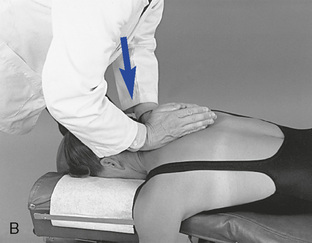
 Figure 5-171
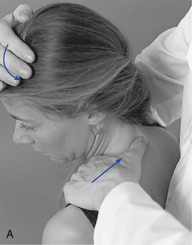
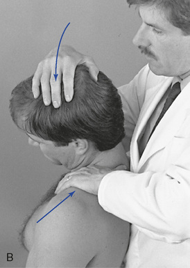
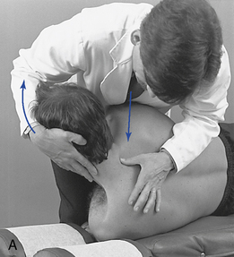
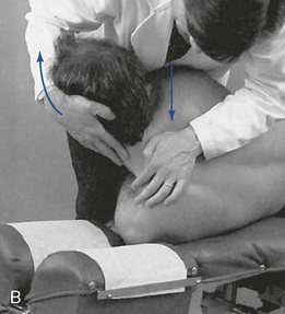
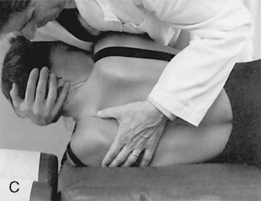
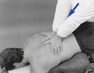
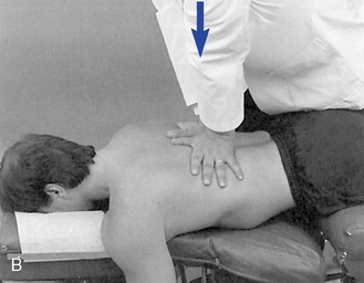
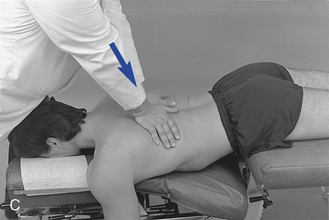
 Figure 5-174
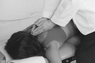
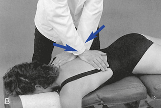
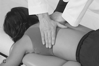
 Figure 5-175
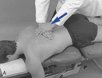
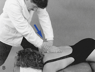
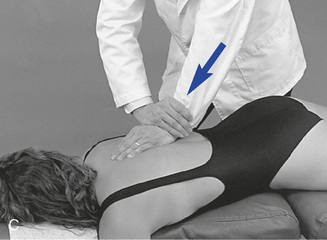
 Figure 5-176
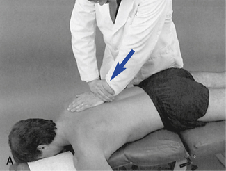
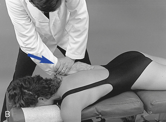
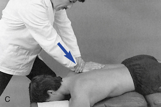
 Figure 5-177
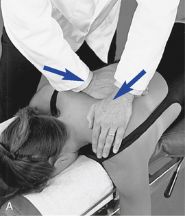
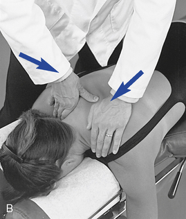
 Figure 5-178
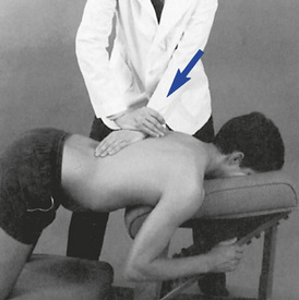
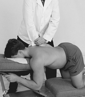
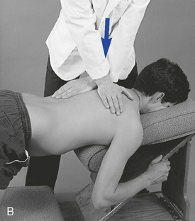
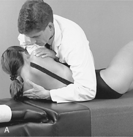
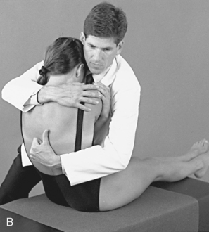
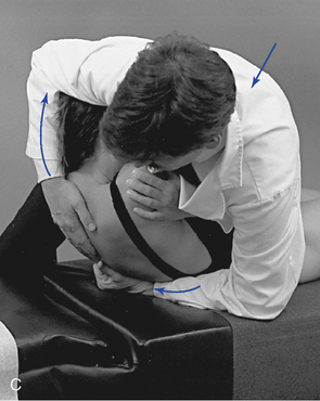
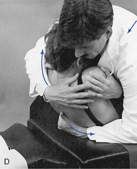
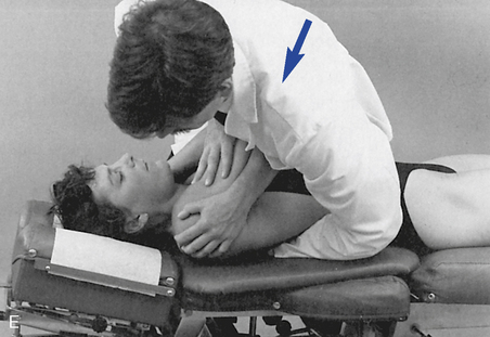
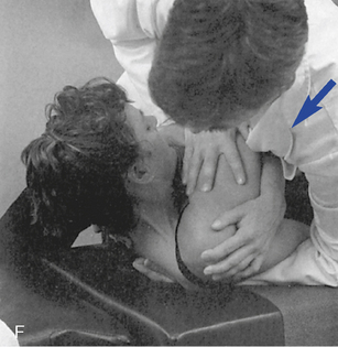
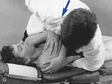
 Figure 5-181
 E, Clenched-fist contact applied to the T8 transverse process to induce extension at the T7–8 motion segment. F, Assisted thenar contact established on the right T3 transverse process to induce left rotation of the right T3–4 articulation. G, Resisted thenar contact applied to the right T4 transverse process to induce right rotation and gapping of the right T3–4 articulation.
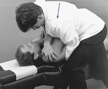
 Figure 5-182
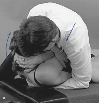
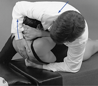
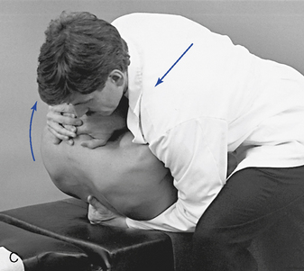
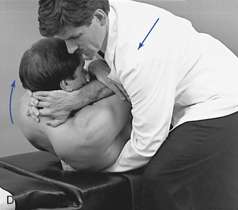
 Figure 5-183
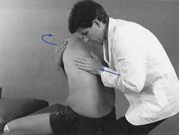
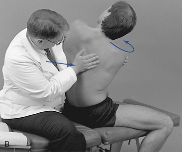
 Figure 5-184
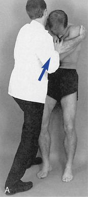
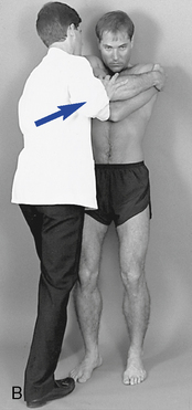
 Figure 5-185
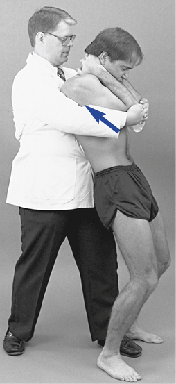
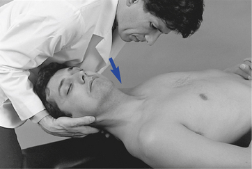
 Figure 5-188
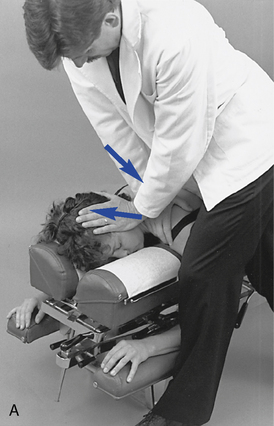
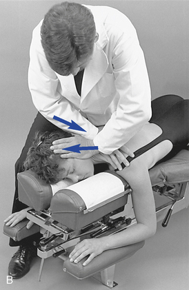
 Figure 5-189
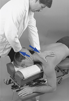
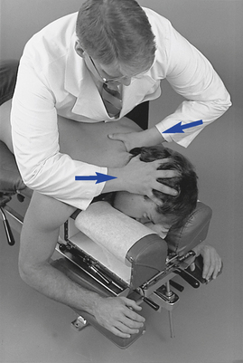
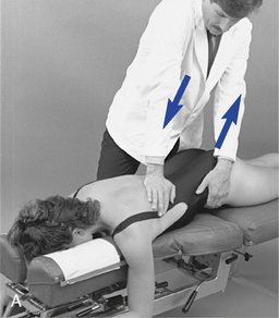
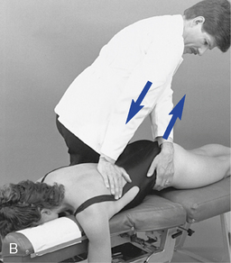
 Figure 5-193
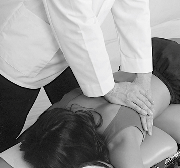
 Figure 5-194
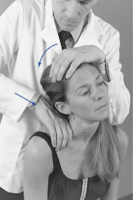
 Figure 5-196
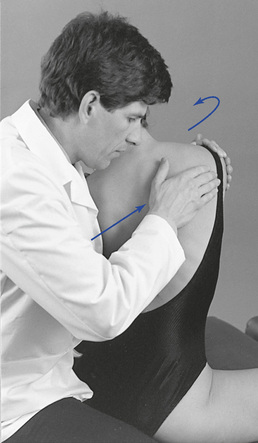
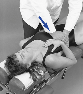
 Figure 5-198