Chapter 5 The Spine
Anatomy, Biomechanics, Assessment, and Adjustive Techniques
Structure and function of the spine
The spine is, among its many other roles, the mechanism for maintaining erect posture and for permitting movements of the head, neck, and trunk. The pelvis helps to form the foundation for posture, and the cervical spine–occipital complex is essentially the postural accommodation unit. The spinal column simultaneously provides stability to a collapsible cylinder while permitting movements in all directions. It supports structures of considerable weight, provides attachments for muscles and ligaments, transmits weight onto the pelvis, and encases and protects the spinal cord while allowing transmission of neural information to and from the periphery.
The functional unit of the spine, the motion segment, is the smallest component capable of performing the characteristic roles of the spine. The motion segment consists of two adjacent vertebrae and their associated structures. It is classically viewed as a three-joint complex, divided into anterior and posterior elements. The disc and vertebral bodies form the anterior joint and the two zygapophyseal joints form the posterior joints (Figure 5-1). The intervertebral joint is therefore a three-joint complex throughout the spine, except for the atlanto-occipital articulation. Changes affecting the posterior joints also affect the disc and vice versa.
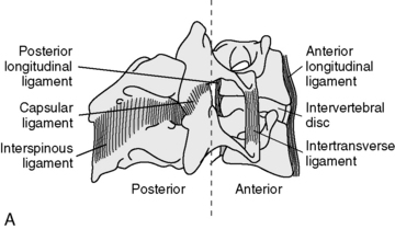
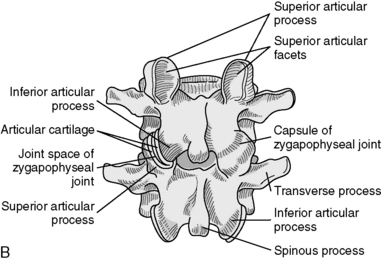
Figure 5-1 Spinal motion segment composed of two vertebrae and contiguous soft tissues: intrinsic ligaments (A) and the posterior joint and joint capsule (B).
(B from White AA, Panjabi MM: Clinical biomechanics of the spine, ed 2, Philadelphia, 1990, JB Lippincott.)
The articulations of the vertebral bodies are synchondroses, or cartilaginous joints, connected by the fibrocartilaginous intervertebral discs (IVDs). In the cervical and lumbar spines, a disc is approximately one third of the thickness of the corresponding vertebral body. In the thoracic spine, this ratio decreases to approximately one sixth of the thickness. This articulation forms the anterior portion of the vertebral motion unit; its chief function is weight-bearing and shock absorption.
Two important ligaments help support the vertebral bodies. These are the anterior longitudinal ligament (ALL) and posterior longitudinal ligament (PLL) (see Figure 5-1). The ALL extends from the inner surface of the occiput to the sacrum. It starts as a narrow band that widens as it descends. It is thickest in the thoracic spine and thinnest in the cervical spine. The PLL runs from the occiput down the posterior portion of the vertebral bodies. It is a somewhat narrow structure that has lateral extensions and covers part of the IVD. It is also thickest in the thoracic spine and equally thin in the cervical and lumbar regions. In the lumbar spine, the PLL tapers, leaving the postero lateral borders of the disc uncovered and unprotected, with important clinical ramifications. Fibers from the PLL attach to the disc itself.
The articulations between the neural arches of vertebrae are diarthrodial joints (refered to as zygapophyseal joints, facet joints, or posterior joints). Each has a joint cavity enclosed within a joint capsule and lined with a synovial membrane (see Figure 5-1). The zygapophyseal joints are true synovial joints and form the posterior portion of the vertebral motion unit. They allow a guiding, gliding action, and the orientation of their joint surfaces is largely responsible for determining the amount and direction of regional spinal motions (Figure 5-2). Furthermore, the facet joints play a significant role in load-bearing. This varies between the facets and the disc, depending on the position of the spine. The facet joints bear an increasing percentage of the load as the spine moves toward an extended position.
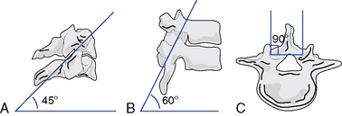
Figure 5-2 Facet planes in each spinal region viewed from the side and above. A, Cervical (C3–C7). B, Thoracic. C, Lumbar.
(Modified from White AA, Panjabi MM: Clinical biomechanics of the spine, ed 2, Philadelphia, 1990, JB Lippincott.)
Support and stability for the posterior joints come from the small segmental ligaments and the joint capsule (see Figure 5-1). The ligamentum flavum, a strong and highly elastic structure, connects adjacent lamina. The interspinous and supraspinous ligaments attach from spinous process to spinous process. Occasionally a bursa forms between these two ligaments. The intertransverse ligaments are relatively thin and run from transverse process to transverse process.
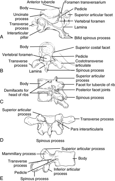
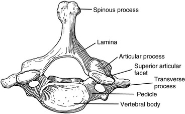
Although each region of the spine has its own unique characteristics, typical vertebrae have common descriptive parts that include a vertebral body, two pedicles, two lamina, four articular processes, two transverse processes, and a spinous process (Figure 5-3). There are in each region, however, atypical vertebrae, which either lack one of these descriptive features or contain other special peculiarities. The atypical vertebrae are C1, C2, C7, T1, T9 to T12, L5, and the sacrum and coccyx. Specific anatomic descriptions and functional characteristics are covered under each specific spinal region.
Evaluation of spinal joint function
The investigation for spinal function incorporates history-taking; physical examination; and, if appropriate, radiographic, laboratory, and special examinations. The interview and examination should be open-ended, efficient, and directed toward identifying the source and nature of the patient’s complaint. This is not to imply that the examination should focus on just the site of complaint; the site of complaint does not necessarily correspond to the source of the dysfunction or pathologic condition. Complaints of pain or aberrant function may have visceral, not somatic, origin, and disorders within the neuromusculoskeletal (NMS) system may be secondary to somatic disease or dysfunction at distant sites. Consequently, the doctor must develop a method to efficiently scan regions of the spine and the locomotor system for possible sites of disease or dysfunction. Within this context, it is impractical to evaluate every joint of the musculoskeletal system during the initial evaluation. The spinal scanning examination should therefore be an abbreviated evaluation designed to quickly scrutinize key areas of spinal joint function. Sites of potential abnormality should then be examined in further detail to assist in the clinical localization of areas of potential joint dysfunction.
Spinal joint scan
The scanning examination of the spine is designed to screen for alterations in structure or function indicative of possible joint subluxation/dysfunction syndromes. It incorporates the assessment of posture, global range of motion (ROM), mobility, and the location of any sites of palpatory pain (Box 5-1).
BOX 5-1 Physical Scanning Evaluation for Joint Dysfunction
Global range of motion
Posture Scan
The evaluation of static posture incorporates both lateral and posterior assessment. The patient stands with the heels separated approximately 3 inches and the forepart of each foot abducted about 8 to 10 degrees from the midline.
On the lateral analysis, visible surface landmarks that ideally coincide with a plumb line are the lobe of the ear, shoulder joint, greater trochanter, and a point slightly anterior to the middle of the knee joint and just anterior to the lateral malleolus (Figure 5-4).
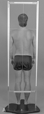
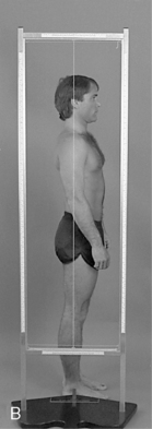
On posterior postural examination, the plumb line should pass through the external occipital protuberance, the spinous processes, the gluteal crease, midway between the knees, and midway between the ankles (see Figure 5-4). Look for specific postural faults, including head tilt, head rotation, shoulder unveiling, lateral curves of the spine, pelvic unleveling, and pelvic rotation. Postural faults that are suspected of having a muscular basis should be followed up with evaluations of muscle length, strength, and volume. Although there is no single ideal posture for all individuals, the best posture for each person is the one in which the least expenditure of energy occurs because the body segments are balanced in the position of least strain and maximal support.
Global Range of Motion
Global ROM evaluation incorporates evaluation of all three cardinal planes of motion. Each range should be recorded and any reduced, aberrant, asymmetric, or painful movements noted. During a scanning examination of the spine, estimations of range are typically conducted without the aid of instrumentation; however, inclinometric measurements may be easily incorporated. Inclinometric measurements are more reliable than visual estimates and are the standard of care in spinal impairment evaluations. The specific ranges and methods for evaluating regional mobility of the spine are discussed later under each separate spinal section.
Regional spinal movements that fall within normal ranges do not necessarily exclude segmental joint dysfunction. Segmental joint hypomobility may be masked by hypermobility at adjacent joints.
Pain Scan
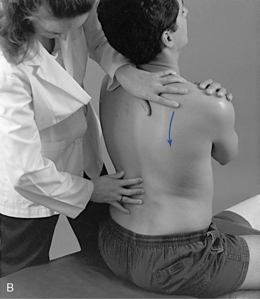
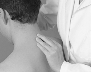
The pain scan is designed to screen for sites of possible abnormal bony or soft tissue tenderness. The superficial soft tissues are assessed with light contacts through the palmar surfaces of the fingers (Figure 5-5, A) or by rolling the superficial layer between the fingers and thumbs (Figure 5-5, B). The deeper paraspinal tissues are evaluated with the same palmar contacts, but more pressure is applied to explore the deeper layer (Figure 5-6). Particular attention is directed to identifying any tenderness in the soft tissues over the posterior joints.
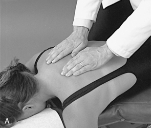
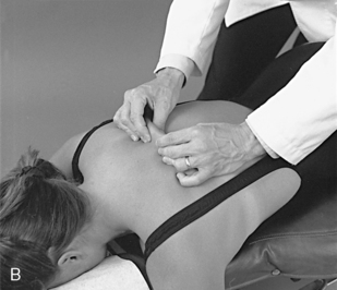
Figure 5-5 Evaluation of skin and superficial soft tissue sensitivity and texture with light palmar contacts (A) and skin-rolling technique (B).
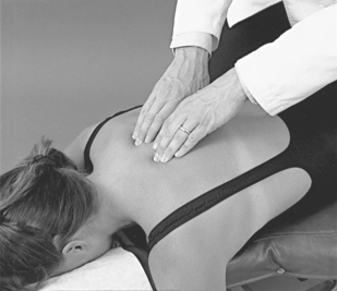
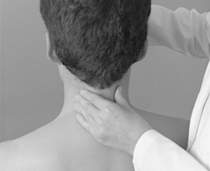
Figure 5-6 Evaluation of the sensitivity, tone, and texture of the deep paraspinal tissues, using the palmar surface of the fingertips.
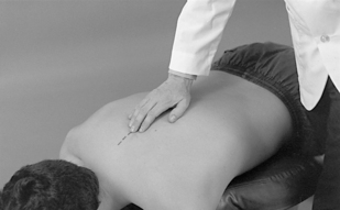
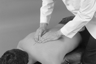
For evaluation of midline bony structures, the spinous processes and interspinous spaces may be scanned with the fingertips of one or both hands. When using a single-hand contact, the doctor rests the middle finger in the interspinous space and the index and ring finger on each side of the spinous process, spanning the interspinous space (Figure 5-7). The middle finger palpates for interspinous spacing and tenderness, and the index and ring fingers palpate for interspinous alignment and lateral spinous tenderness. When the fingers of both hands are applied, the fingertips meet at the midline to palpate interspinous alignment and tenderness (Figure 5-8).
The lumbar spine and thoracic spine are customarily examined in the prone position. Although the cervical spine may be evaluated in the prone or supine position, it is more commonly evaluated in the supine position with bilateral fingertip contacts.
Motion Scan
Evaluation of spinal mobility incorporates tests to scan regional joint play (JP), passive ROM, or end play. JP may be evaluated with the patient in a sitting or prone position, or in the supine position for the cervical spine. Passive ROM or EP is screened in the sitting position or supine position in the cervical spine. In both cases, the doctor establishes broad contacts against the spinous processes or broad bilateral contacts over the posterior joints. When JP is evaluated, the area evaluated should be positioned as close to the loose-packed neutral position as possible.
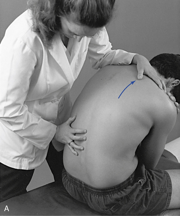
When evaluating sitting JP, the doctor sits or stands behind the patient and places the nonpalpating arm across the patient’s shoulders (Figure 5-9) or under the patient’s flexed arms. The flexed-arm position is commonly used in the middle to upper thoracic spine and is developed by having the patient interlace his or her fingers behind the neck (Figure 5-10). In the cervical spine, the indifferent hand (IH) supports the crown of the patient’s head (Figure 5-11).
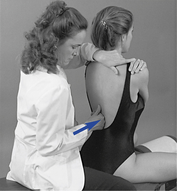
 Figure 5-9
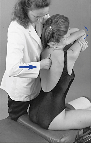
 Figure 5-10
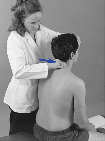
 Figure 5-11
With the patient prone, the doctor establishes bilateral contacts on each side of the spine or a reinforced contact over the spinous processes (Figure 5-12). To scan the spine, slide up or down, applying gentle posterior-to-anterior (P-A) springing movements. Regions of induced pain or inappropriate movement should be noted for further evaluation.
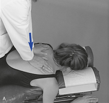
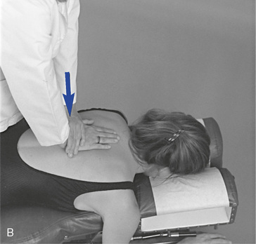
 Figure 5-12 Prone joint play scan, using bilateral thenar contacts over the transverse processes (A) and reinforced hypothenar contact over the spinous process (B).
To screen sections of the spine for possible movement restriction, place the patient in the sitting position, with the arms crossed over the chest. The doctor may either sit behind the patient or stand at the patient’s side (Figure 5-13). Trunk movement is controlled by establishing contacts across the patient’s shoulder or by reaching around to grasp the patient’s forearm. Cervical movement is directed by establishing a contact on the crown of the patient’s head or forehead (Figure 5-14). These procedures are not designed to assess JP; rather, they are applied to evaluate full ROM with overpressure. Palpation contacts are established with the fingertips, palm, or thenar surface of the doctor’s palpation hand. The contacts should be broadly placed so that movement at two to three motion segments may be scanned together.

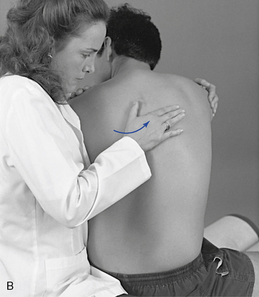
 Figure 5-13 A, Evaluation of left lateral flexion movement, with the doctor standing. A broad thenar contact is established along the left side of the spinous processes. B, Evaluation of left rotation movement, with the doctor seated. A broad thenar contact is established along the left side of the spinous processes.
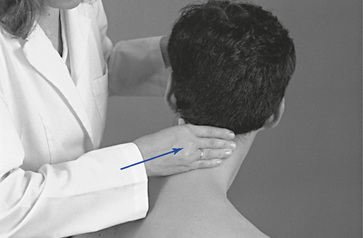
Figure 5-14 Evaluation of right cervical rotation, with the doctor’s indifferent hand contacting the patient’s forehead. The palmar surfaces of the doctor’s right digits establish palpation contacts over the patient’s right articular pillars.
For lateral flexion and rotation assessment of the lumbar or thoracic region, contacts are established on the lateral surface of the spinous processes on the side of induced rotation or laterally bending (see Figure 5-13). In the cervical spine, the fingertips establish the contacts over the articular pillars (see Figure 5-14). For spinal flexion and extension, the contacts are established with the dorsum of the hand or fingertip contacts over the interspinous spaces of several adjacent segments (Figure 5-15). To evaluate movement, guide the patient through the full ROM and induce gentle overpressure at end range. During the assessment, any regional sites of elicited pain or perceived increased or decreased resistance should be noted. JP and regional motion scanning of the cervical spine are commonly performed in a supine position.
Alignment Scan
Evaluation of joint alignment screens for asymmetric relationships on a sectional basis. Broad hand contacts are placed over the lateral transverse processes (paraspinal region), noting any posterior prominence indicative of rotational asymmetry. The index and middle fingers can also scan the interspinous spaces for widening or narrowing, indicative of flexion or extension asymmetries.
The lumbar spine and thoracic spine are customarily examined in the prone position. Although the cervical spine may be evaluated in the prone or supine position, it is more commonly evaluated in the supine position, using bilateral fingertip contacts.
Identification of joint subluxation/dysfunction syndrome
As stated previously, the goal of manual joint assessment procedures is to identify possible sites of motion segment dysfunction. Many of the procedures used to scan the spine are also applied in the investigation and localization of dysfunction (Box 5-2). However, they are applied within a different context to identify more precisely the site and nature of the dysfunction/subluxation syndrome under question. They incorporate the detailed exploration of painful sites; the assessment of joint alignment and the texture, tone, and consistency of associated soft tissues; and the precise evaluation of intersegmental movements and end play. The evaluation of painful tissues often incorporates the application of various directions of applied pressure to determine the directions of painful movement. These procedures are referred to as joint challenging or joint provocation testing.
BOX 5-2 Isolation of Motion Segment Dysfunction (PARTS)
Goal
Neither scanning (see Box 5-1) nor isolation evaluation, alone or in combination, constitutes a complete examination. The doctor of chiropractic must be competent in performing a complete physical evaluation to assess the nature of the patient’s condition and to determine if the patient is suitable for chiropractic care.
Evaluation of segmental alignment involves comparing adjacent vertebral segments for symmetry and examining interspinous spaces, spinous processes, cervical articular pillars, thoracic transverse processes, rib angles, and lumbar mammillary processes. Sudden changes in interspinous spacing may identify flexion or extension malposition. Rotational malpositions may be identified by misalignment of adjacent spinous processes and unilateral prominence of the cervical articular pillars, thoracic transverse processes, or lumbar mammillary processes. The articular pillars, transverse processes, and mammillary processes are not as distinctly palpable as the spinous processes, but they are less susceptible to congenital or developmental anomaly. Unilateral contraction of segmental muscles produces a sense of fullness and may be mistaken for underlying rotational malposition of the articular pillars, transverse processes, or mammillary processes.
The localization of soft tissue changes also helps in specifying the nature and site of joint disease or derangement. Injured or inflamed joints may be associated with an overlying sense of increased warmth or puffiness. Joint disease or dysfunction is also commonly associated with local soft tissue reactive changes in the segmentally related tissue. This may lead to sites of asymmetric muscle tone and sites of abnormal tenderness (allodynia). Long-standing dysfunction may be associated with local areas of induration and contracture. These sites may palpate as areas of deep nodular or rope-like consistency.
Segmental motion palpation and end-play tests are applied to identify those segmental movements that are increased, restricted, or painful. Pain elicited at one level and not adjacent levels helps localize the site of possible dysfunction. Increased resistance identifies a site of possible joint fixation, and increased movement identifies a site of possible clinical joint instability. The identification and location of soft tissue alterations, pain, and end-play restriction are fundamental to identifying the level and the direction of possible restriction. Furthermore, they are often essential to determining the type and directions of applied adjustive therapy.
Although all of the physical examination procedures discussed are an integral part of joint evaluation, it must not be forgotten that all have limitations. Many are based on the evaluation of symmetry in structure and function, and the degree of variation necessary to produce disease or dysfunction has not been determined. Asymmetry of structure and function is common, and minor abnormalities in alignment and motion may be within the range of normal variation. Furthermore, physical joint examination procedures depend on the skill of the examiner and are susceptible to errors in performance or interpretation. As discussed in Chapters 3 and 4 the present ability to precisely identify and adjust a single spinal segment may be limited and not directly related to clinical outcome. Based on this information, some have suggested that clinicians should focus on identifying regional sites (several segments) of dysfunction.1 2 3 4 It must also be remembered that the identification of dysfunction does not necessarily identify the cause.
All of these concerns lead to the necessity of incorporating outcome measures in the evaluation of patient care and contrasting all of the history and examination findings before a diagnostic conclusion is reached and therapy is applied.
Cervical spine
The cervical spine has the precarious task of maintaining head posture while allowing for a great deal of mobility. The cervical spine must balance the weight of the head atop a relatively thin and long lever, making it quite vulnerable to traumatic forces. The cervical facets allow movement in all directions; the cervical spine is therefore the most movable portion of the vertebral column. The cervical spine has two anatomically and functionally distinct regions, which are considered individually.
Functional anatomy of the upper cervical spine
The upper cervical spine is the most complex region of the axial skeleton. It is composed of the atlanto-occipital and atlantoaxial articulations, which serve as a transition from the skull to the rest of the spine. These two functional units are anatomically and kinematically unique. Neither has an IVD, and the atlantoaxial articulation incorporates three synovial joints.
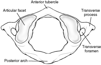
The atlas has no vertebral body or spinous process (Figure 5-16). It consists of a bony oval, with the two lateral masses connected by the anterior and posterior arches. The lateral masses, formed from enlarged pedicles, have concave articular facets superiorly for articulation with the occipital condyles and circular inferior facets for articulation with the axis.
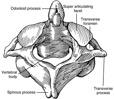
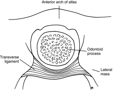
The outstanding feature of the axis (C2) is the presence of the odontoid process (dens) (Figure 5-17). The odontoid is formed by the fusion of the embryologic remnants of the vertebral body of the atlas to the superior aspect of the body of the axis. The spinous process of the axis is large and bifid, and it is the first palpable midline structure below the occiput. The superior articular surfaces project from the superior aspect of the pedicles to meet the inferior aspects of the atlas’ lateral masses. Their surfaces are convex and lie in the transverse plane, with a slight downward lateral slant. The atlantoaxial articulation is formed by articular surfaces of the C1–2 lateral masses. Both articular surfaces are convex, allowing for considerable mobility in rotation. The atlanto-odontal articulation is formed by the anterior arch of the atlas and the odontoid process. The odontoid process is completely surrounded by the anterior arch of the atlas anteriorly, the lateral masses laterally, and the transverse ligament posteriorly (Figure 5-18). It is a trochoid joint, providing a pivot action.
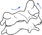
The atlanto-occipital articulation is a freely movable synovial condyloid articulation (Figures 5-19 and 5-20). The articular surfaces of the condyles are convex and converge anteriorly, resembling curved wedges that fit into matching concave surfaces in the lateral masses of the atlas. Individual axes for each condyle exist, demonstrating that there is no single axis for axial rotation. The axis of movement for rotation occurs at two points (eccentrically located), thus resulting in very little active rotation. Each condyle can move a degree or two forward and backward without the other side moving much.
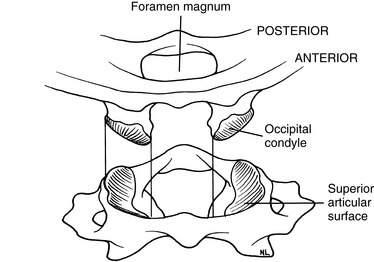
Figure 5-19 The atlanto-odontoid articulation has convex occipital condyles that fit into the concave lateral masses of the atlas.
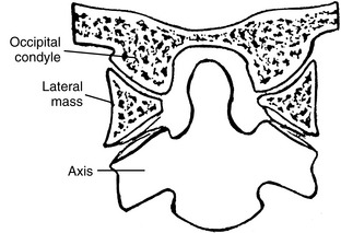
Figure 5-20 A coronal section through the atlanto-occipital and atlantoaxial articulations, showing the plane of the facets.
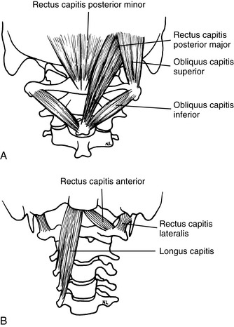
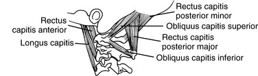
The muscles that provide the forces necessary for movement, postural support, and primary stability of the upper cervical region include the rectus capitis posterior major, rectus capitis posterior minor, rectus capitis lateralis, rectus capitis anterior, superior oblique, and inferior oblique (Figures 5-21 and 5-22). All of these muscles are supplied with motor fibers from the first cervical nerve and proprioceptive and pain fibers via a communicating branch from the second cervical nerve.
The ligaments that provide added stability to the upper cervical spine include the transverse ligament of the atlas, alar ligaments, PLL, posterior atlanto-occipital membrane, anterior atlantooccipital membrane, ligamentum nuchae, and the apical ligament (Figure 5-23). Because the ligaments of the upper cervical spine can be damaged by trauma, weakened by systemic inflammatory diseases, or congenitally absent or malformed, testing for their integrity should be done before manipulative therapy is begun. If instability is suspected, flexion-extension stress x-ray examinations should be performed.
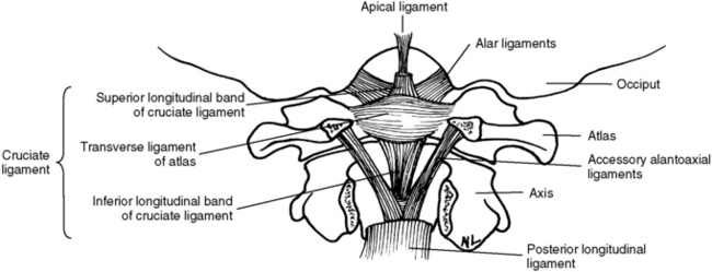
Figure 5-23 Upper cervical spinal ligaments shown with the posterior arch of the atlas and axis removed.
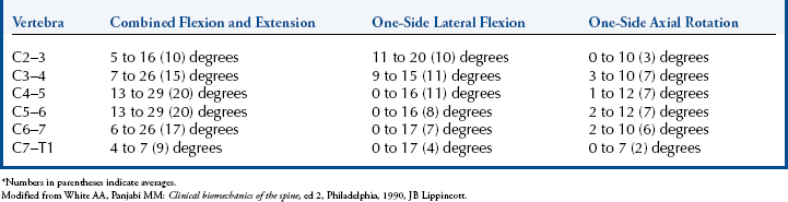
Range and Pattern of Motion of C0–C1
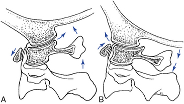
The principle movement that occurs in the atlanto-occipital articulation is flexion and extension.5 The combined range is approximately 25 degrees (Table 5-1 and Figure 5-24). Flexion and extension movements at C0–1 are predominantly angular movements in the sagittal plane, without any significant associated coupled motions. During flexion the occipital condyles glide posterosuperiorly on the lateral masses of the atlas as the occipital bone separates from the posterior arch. During extension, the condyles slide anteriorly on the lateral masses of the atlas while the occipital bone approximates the posterior arch of atlas (Figure 5-25).
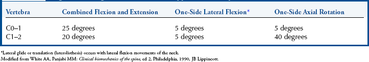
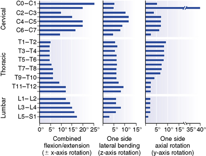
Figure 5-24 Representative values for rotatory range of motion at each level of the spine.
(From White AA, Panjabi MM: Clinical biomechanics of the spine, ed 2, Philadelphia, 1990, JB Lippincott.)
Axial rotation at the C0–1 articulation was previously thought to be very limited.6 However, recent studies have demonstrated a range of 4 to 8 degrees to each side.5 Rotational movement is limited by the articular anatomy and the connections of the alar ligaments. The movement that does occur is predominantly in the elastic range at the end of total cervical rotation, where it is usually coupled with some small degree of lateral flexion.7
Lateral flexion of the atlanto-occipital articulation approximates that of axial rotation. Although the articular design of the atlanto-occipital articulation should allow for greater flexibility in lateral flexion, it appears that the attachments of the alar ligament function to limit this motion (Figure 5-26). Movement occurs primarily in the coronal plane, although it is typically associated with some small degree of coupled rotation in the opposite direction. This leads to rotation of the chin away from the side of lateral flexion. The predominant movements occurring at the articular surface during lateral flexion are coronal plane rotation (roll) and translation (slide). Roll and slide occur in opposite directions because of the convex shape of the occipital condyles and the concave shape of the atlas articular surface. Rotation (roll) occurs in the direction of lateral flexion, and translation (slide) occurs in the direction opposite the lateral flexion (Figure 5-27).
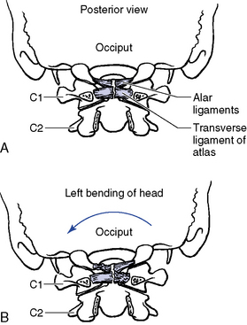
Figure 5-26 The role of the alar ligaments in lateral flexion of the atlanto-occipital articulation. A, Posterior view in the neutral position. B, Left lateral flexion. Motion is limited by the right upper portion and the left lower portion of the alar ligaments.
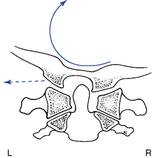
Figure 5-27 Right lateral flexion of the atlanto-occipital articulation, demonstrating rolling of the occiput to the right (solid arrow) and sliding to the left (broken arrow).
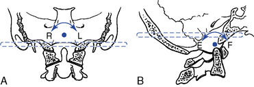
The instantaneous axes of rotation (IAR) have not been experimentally determined for the atlanto-occipital articulation. The axes were estimated “by determining the centers of the arches formed by the outline of the joints in the sagittal and frontal planes”5 (Figure 5-28).
Range and Pattern of Motion of C1–2
The principal movement that occurs at the atlantoaxial joint is axial rotation. Segmental range averages 40 degrees to each side, contributing to more than half of the total cervical rotation. The first 25 degrees of cervical rotation occur primarily in the atlantoaxial joint.7 During rotation the lateral mass and articular surface slide posteriorly on the side of rotation and anteriorly on the side opposite rotation. The motion occurs about a centrally located axis within the odontoid process (Figure 5-29). An additional subtle vertical displacement of the atlas takes place with rotation as a result of the biconvex structure of the articular surfaces (Figure 5-30).
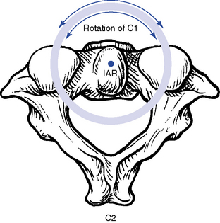
Figure 5-29 The theoretic location of the instantaneous axis of rotation for the atlantoaxial articulation in axial rotation.
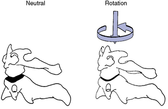
Figure 5-30 Because the articular surfaces are both convex, as the atlas rotates on the axis, a subtle vertical displacement occurs, causing the two segments to approximate one another.
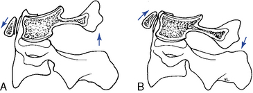
Flexion and extension movements of the atlas on the axis occur as rocking movements as a result of the biconvex facet surfaces. The IAR is located in the middle third of the dens. In flexion, the posterior joint capsule and posterior arches separate, and the atlas articular surface glides forward. In extension, the posterior joint capsule and posterior arches approximate, and the atlas articular surface glides posteriorly (Figure 5-31). Also, the anterior arch of the atlas must ride up the odontoid process during extension and down during flexion. Flexion and extension movements of the atlantoaxial joint are also associated with small translational movements from 2 to 3 mm in the adult up to 4.5 mm in the child.5 Any movement greater than these ranges should trigger an evaluation to assess the stability of the C1–2 articulation and the integrity of the odontoid and transverse ligaments.
Compared with rotation, lateral flexion of the atlantoaxial articulation is limited, averaging approximately 5 degrees to each side.7 It has been suggested that lateral flexion is coupled with translation; however, this is a controversial subject.5 The associated translation is purported to occur toward the side of lateral flexion. In other words, right lateral flexion of the cervical spine would be associated with translation of C1 to the right (Figure 5-32).
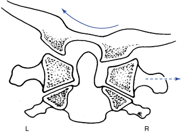
Figure 5-32 Right lateral flexion of the upper cervical spine (solid arrow) with translation of the atlas (broken arrow) toward the right.
Further clouding the issue is the apparent translation that may be visible on an anterior-to-posterior open-mouth (APOM) radiograph with rotational subluxation of the atlas. Rotational movement of the lateral masses about the odontoid process may induce an apparent lateral translation of the atlas on the APOM radiograph as a result of projectional widening and narrowing of the lateral masses (Figure 5-33).
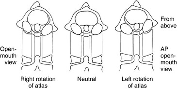
Figure 5-33 Atlas rotation produces a wider lateral mass and narrower appearance of the atlanto-odontal interspace on the side of posterior rotation. This may lead to a false impression of a lateral flexion or translational malposition of the atlas on the anterior-to-posterior open-mouth radiograph.
Functional anatomy of the lower cervical spine (C3–C7)
The typical cervical vertebrae (C3–C6) possess the same structural parts as all other true vertebrae, plus some unique and distinctive physical features (Figure 5-34). The spinous processes are bifid to allow for better ligamentous and muscular attachment. Each transverse process from C6 upward contains the transverse foramen, allowing for the passage of the vertebral artery. The body of the typical cervical vertebra has anterior and posterior surfaces that are small, oval, and wide transversely. The anterior and posterior surfaces are flat and of equal height. The posterior lateral aspect of the superior margin of the vertebral bodies is lipped, forming the uncinate processes, which serve to strengthen and stabilize the region. The uncovertebral articulations (joints of Von Luschka) are pseudojoints that have a synovial membrane with synovial fluid but no joint capsule (Figure 5-35). They serve as tracts that guide the motion of coupled rotation and lateral flexion. They begin to develop at 6 years of age and are complete by 18 years of age.
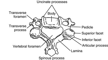
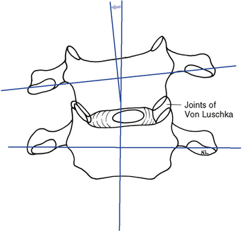
Figure 5-35 The uncinate processes limit pure lateral flexion to only a few degrees while serving as guides to couple lateral flexion with rotation.
The articular facets are teardrop-shaped, with the superior facet facing up and posteriorly and the inferior facet facing down and anteriorly, placing the joint space at a 45-degree angle midway between the coronal and transverse planes (Figure 5-36). The disc height–to–body height ratio is greatest (2:5) in the cervical spine, therefore allowing for the greatest possible ROM (Figure 5-37).
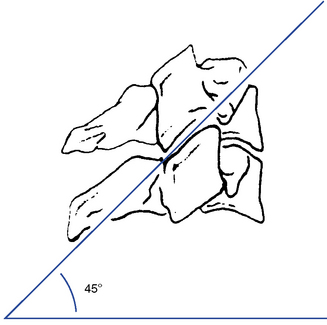
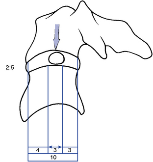
Figure 5-37 The location of the nucleus pulposus and the disc height–to–body height ratio in the cervical spine.
The short and rounded pedicles of cervical vertebrae are directed posterolaterally. The superior and inferior vertebral notches in each pedicle are the same depth. The laminae are long, narrow, slender, and sloping. The intervertebral foramina in this region are larger than in the lumbar or thoracic areas and are triangular in shape.
The C7 vertebra (vertebra prominence) is considered the atypical segment of the lower cervical spine. It demonstrates anatomic characteristics of both the cervical vertebra and the thoracic vertebra. It has a spinous process that is quite long and slender, with a tubercle on its end. The inferior articular processes are similar to those in the thoracic spine, and the superior processes match those of the typical cervical vertebra. C7 has no uncinate processes and no transverse foramen. The transverse processes are large, broad, and blunt. The transverse processes may become enlarged or develop cervical ribs, with the potential to create thoracic outlet compromise (Figure 5-38).
Cervical Curve
The cervical spine forms a lordotic curve that develops secondary to the response of upright posture. The functions of the cervical curve and the anterior-to-posterior (A-P) curves throughout the spine are to add resiliency to the spine in response to axial compression forces and to balance the center of gravity of the skull over the spine. The center of gravity for the skull lies anterior to the foramen magnum (Figure 5-39).
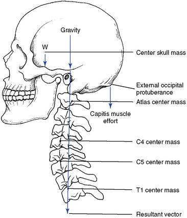
Figure 5-39 The center of gravity for the skull. If the cervical curve changes, the center of gravity shifts.
The facet and disc planes in large part determine the degree of potential lordosis. Congenital diversity in pillar height and facet angulation therefore leads to significant variation in the degree of cervical lordosis present in the population. In addition, degenerative changes or stress responses in these structures may change the “normal” lordosis.
There are a number of opinions as to what the normal cervical curve should be and how it should be measured.6,8 9 10 11 12 13 14 There is also significant debate on what constitutes an abnormal curve and what biomechanical consequences, if any, will result from alteration in the cervical lordotic curve. A reduced cervical curve (hypolordosis) has the potential to shift more weight onto the vertebral bodies and discs and increase muscular effort as the posterior neck muscles work to maintain head position and spinal stability. An increased cervical curve (hyperlordosis) will potentially increase the compressive load on the facets and posterior elements (Figure 5-40).
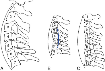
Figure 5-40 The cervical curve extending from C1 to T2. A, Normal. B, Hypolordosis with a kyphosis involving the middle segments. C, Alordotic.
Various methods for radiographically measuring lordosis have been suggested. The most common method involves direct measurement of the curve by forming an angle between a line extending through the center of C1, with a line drawn along the inferior endplate of C7 (Figure 5-41). Although the cervical lordosis apparently extends to the T1–2 motion segment, measurements commonly use the C7 level as the lowest point reliably viewed on a lateral cervical x-ray film. Another method presented by Jochumsen12 proposes classifying the cervical curve by measuring the distance from the anterior body of C5 to a line running from the anterior arch of the atlas to the anterior superior aspect of the body of C7 (Figure 5-42). There is some agreement that the cervical curve midpoint is the C5 vertebra (C4–5 interspace).
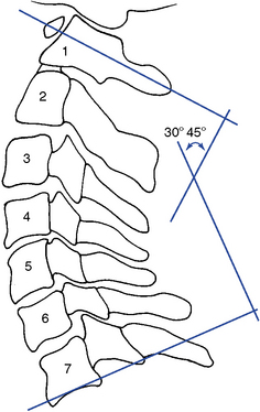
Figure 5-41 The angle of the cervical curve should be about 30 to 45 degrees when measured between lines drawn through C1 and C7.
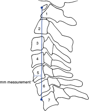
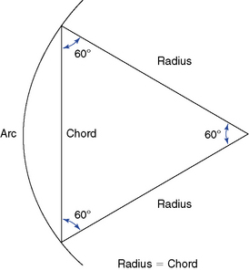
The proposed optimal curve for the cervical spine can be extrapolated from the mechanical principle that states the strongest and most resilient curve is an arc that has a radius of curvature equal to the cord across the arc (Figure 5-43). The length of the radius, and hence the cord, should equal approximately 7 inches or 17 cm. As the radius increases, the curve increases (flattens, as in hypolordosis) and vice versa.
Range and Pattern of Motion of the Lower Cervical Spine
The lower cervical spine exhibits its greatest flexibility during flexion and extension movements (Table 5-2; see Figure 5-24). Lateral flexion exhibits slightly greater movement than rotation. Both rotation and lateral flexion decrease significantly at the thoracocervical junction.
Flexion and Extension
Movement averages approximately 15 degrees of combined flexion and extension per segment and is greatest at the C5–6 motion segment.15 Flexion and extension occur around an axis located in the subjacent vertebra and combine sagittal plane rotation with sagittal plane translation (Figure 5-44). This pattern of combined segmental angular tipping and gliding develops a stairstep effect, which is noted on flexion and extension radiographs.
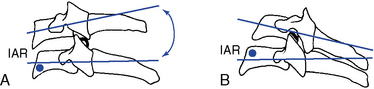
Figure 5-44 Sagittal plane movement of a cervical motion segment in flexion (A) and extension (B), locating the instantaneous axis of rotation and the stair-stepping appearance that occurs with combined tipping and gliding movements.
With flexion, the articular joint surfaces slide apart, producing stretching of the facet joints and posterior disc and anterior disc approximation and compression. With extension, the opposite occurs. The disc is subjected to compression on the concave side and tension on the convex side. The side of the disc subjected to tension retracts and the side subjected to compression bulges.5 The net effect of these two opposing forces is to limit shifting of the nucleus pulposus during movements of flexion and extension and lateral flexion (Figure 5-45). Krag and colleagues16 implanted small metal markers within the lumbar and thoracic IVDs and confirmed the bulging and retraction of the discs during lumbar segmental flexion movements. However, they did note some minor posterior migration of the nucleus that was not identified by previous mathematical models. This phenomenon has not been investigated for the cervical spine.
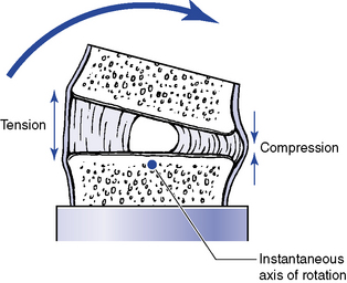
Figure 5-45 Representation of changes in the disc with flexion, as well as extension, or lateral flexion movements.
The coupled translation that occurs with flexion and extension has been measured at approximately 2 mm per segment, with an upper range of 2.7 mm.17 Translational movements do not occur evenly throughout the cervical spine.15 For every degree of sagittal plane rotation, more translation occurs in the upper cervical segments than in the lower cervical segments. This leads to a flatter arch of movement in the upper cervical spine (Figure 5-46). Accounting for radiographic magnification, White and Panjabi5 have recommended 3.5 mm as the upper end of normal translational movement in the lower cervical segments. Translation beyond 3.5 mm suggests end range segmental instability.
Lateral Flexion
Lateral flexion averages approximately 10 degrees to each side in the midcervical segments, with decreasing flexibility in the caudal segments. The IAR for lateral flexion has not been determined. Speculation places the axis in the center of the subjacent vertebral body (Figure 5-47).
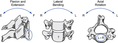
Figure 5-47 The theoretic locations for the instantaneous axis of rotation for each plane of movement in the lower cervical spine.
(From White AA, Panjabi MM: Clinical biomechanics of the spine, ed 2, Philadelphia, 1990, JB Lippincott.)
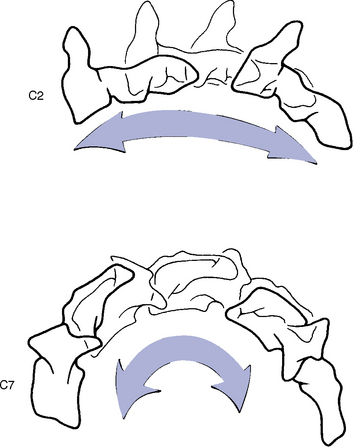
Lateral flexion in the lower cervical spine is coupled with rotation in the transverse plane. The coupling is such that lateral flexion and rotation occur to the same side. This leads to posterior vertebral body rotation on the side of lateral flexion, thereby causing the spinous processes to deviate to the convexity of the curve (Figure 5-48). The degree of coupled axial rotation decreases in a caudal direction.14 At the second cervical vertebra there are 2 degrees of coupled rotation for every 3 degrees of lateral bending, and at the seventh cervical vertebra there is only 1 degree of coupled rotation for every 7.5 degrees of lateral bending.
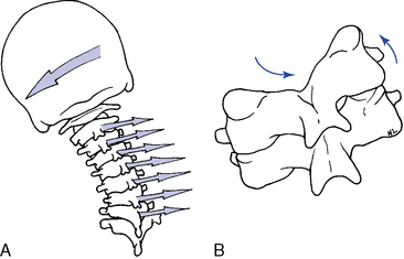
Figure 5-48 A, Left lateral flexion coupled with physiologic left rotation. B, Movement of the facet surfaces with left lateral flexion and coupled left rotation in the lower cervical spine.
During lateral flexion the facets on the side of lateral flexion (concave side) slide together as the inferior facet slides inferomedially because of the coupled rotation. On the opposite side, the facets distract and the inferior facet slides superiorly. The IVD approximates on the side of lateral flexion and distracts on the opposite side.
Rotation
ROMs for segmental axial rotation on average are slightly less than those for lateral flexion, with a similar tendency for decreased movement in the lower cervical segments, especially at the C7–T1 motion segments. The axis of rotation is also somewhat speculative and has been placed by Lysell14 in the anterior subjacent vertebral body (see Figure 5-47).
Rotational movements in the lower cervical spine demonstrate the same coupling as described for lateral flexion. In other words, left or right axial rotation is coupled with lateral flexion to the same side. This leads to a pattern of motion in which, on the side of cervical rotation (posterior body rotation), the inferior facet of the superior vertebra glides posteroinferiorly as the contralateral glides anterosuperiorly (Figure 5-49).
Cervical Kinetics
Nonsegmental muscles produce integrated global movement of the cervical spine as a result of the head’s moving in relation to the trunk. Concentric and eccentric muscle activity is combined, with eccentric activity predominating during flexion, extension, and lateral flexion. Concentric muscle activity refers to the development of sufficient muscle tension to overcome a resistance, causing the muscle to visibly shorten and the body part to move. However, eccentric muscle activity occurs when a given resistance overcomes the muscle tension, causing the muscle to actually lengthen. Relaxation of a muscle against the force of gravity, creating a deceleration of the moving body part, is an example of eccentric muscle activity.15
The segmental (intrinsic) muscles function to coordinate and integrate segmental motion. The intrinsic muscles act as involuntary integrators of overall movement. Movements of the head initiate normal movements of the cervical spine, but with conscious effort, movement may be initiated at lower segmental levels. They operate by the same concentric and eccentric principles as the larger nonsegmental muscles.
Flexion is initiated by anterior cervical muscles and controlled or limited by eccentric activity of the semispinalis, longissimus, and splenius muscle groups. Flexion is further limited by the elastic limits of myofascial tissue, nuchal ligament, joint capsule, PLL, ligamentum flavum, posterior IVD, anterior vertebral bodies, and the chin hitting the chest.
Posterior cervical muscles controlled or limited by the eccentric activity of the sternocleidomastoid (SCM), scaleni, and longus coli muscle groups initiate extension. Extension is further limited by the elastic limits of the myofascial tissue, anterior IVD, ALL, joint capsule, posterior vertebral bodies, and articular pillars.
Lateral flexion is initiated by ipsilateral contraction and controlled or limited by the contralateral eccentric activity of the splenius capitis, semispinalis cervices, and longus coli muscle groups. Lateral flexion is further limited by the elastic limits of some myofascial tissue, contralateral joint capsule, periarticular ligaments, flaval ligament, IVD, ipsilateral joint capsule, and ipsilateral articular pillars.
Rotation is initiated by concentric contraction of the ipsilateral splenius capitis and cervicis, longissimus cervicis, and contralateral semispinalis muscles. Eccentric muscle contraction occurs simultaneously to guide and break movements and involves action of the contralateral splenius capitis, cervicis, longissimus cervicis, and ipsilateral semispinalis and scaleni muscles. Movement is further limited by capsular and periarticular ligaments and segmental muscles.
Evaluation of the cervical spine
Observation
Examination of the cervical spine begins with a visual examination of the alignment and ROM of the cervical spine in the sagittal, coronal, and transverse planes. Alignment in the coronal plane is evaluated by observing the orientation of the head relative to the trunk and shoulders, the leveling of the mastoid processes, and the symmetry of the cervical soft tissues. Observing the status of the cervical curve and orientation of the patient’s chin assesses sagittal plane alignment. Tucking or elevation of the chin in the presence of a normal cervical curve may indicate upper cervical dysfunction. Observing the patient from the posterior and noting any turning of the head (Figure 5-50) may assess orientation of the head in the transverse plane.
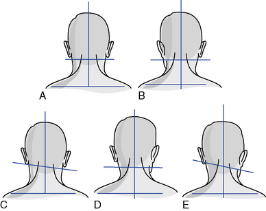
Figure 5-50 Common cervical postural presentations. A, Normal. B, Occiput in left posterior rotation. C, Occiput in right lateral flexion or atlas in left laterolisthesis. D, Atlas in right rotation. E, Axis in rotation and right lateral flexion.
(Modified from Pratt NE: Clinical musculoskeletal anatomy, Philadelphia, 1991, JB Lippincott.)
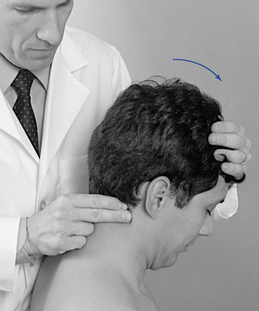
Global ROM is most effectively evaluated in the sitting position. Take care to observe for recruitment of trunk movement and stabilize the shoulders if necessary. During flexion the patient should be able to touch the chin to the chest, and during extension look straight toward the ceiling. During rotation the patient should be able to approximate the chin to the shoulder, and during lateral flexion approximate the ear to within two to three fingers’-width of the shoulder (Figure 5-51). Variations with sex and age are quite common. If ROM is evaluated in circumstances other than screening evaluations, it should be conducted with the use of inclinometry for more accurate recordings of the ranges (see Figure 3-11 and Table 5-3).
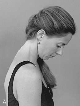
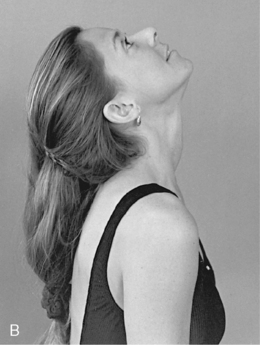
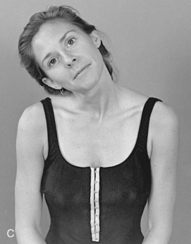
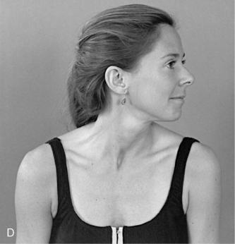
Figure 5-51 Cervical global range of motion. A, Flexion. B, Extension. C, Right lateral flexion. D, Left rotation.
TABLE 5-3 Global Range of Motion for the Cervical Spine
| Motion | Normal Range | Range Without Impairment |
|---|---|---|
Static Palpation
Palpation for alignment, tone, texture, and tenderness of the bony and soft tissue structures of the neck is conducted with the patient in the supine or sitting position. During supine evaluation, stand or kneel at the head of the table, and during the seated evaluation, stand behind the patient.
Upper Cervical Spine
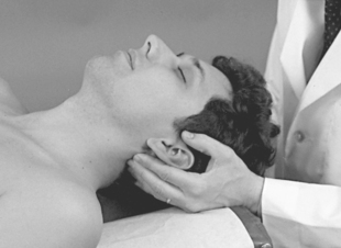
The suboccipital muscles are evaluated by using the palmar surfaces of the fingertips to make a bilateral comparison of tone, texture, and tenderness (Figure 5-52). Bony alignment of the atlanto-occipital joint is evaluated by placing the tip of the index finger in the space between the mandibular ramus and the anterior tip of the atlas transverse process and between the inferior tip of the mastoid process and the atlas transverse process (Figure 5-53).
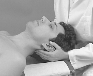
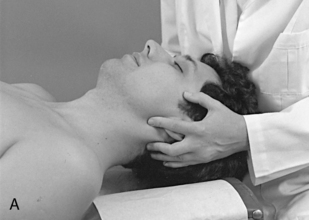
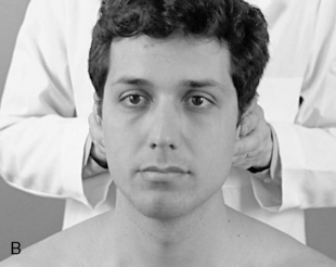
Figure 5-53 Palpation for flexion, extension, or rotation alignment (A) and lateral flexion alignment of the atlanto-occipital articulation (B).
Spacing between the atlas transverse process and the mandibular ramus and between the atlas transverse process and mastoid processes should be symmetric on both sides. Malpositions between C0 and C1 can affect the spacing between the mandibular ramus and the C1 transverse process. The space between the angle of the jaw and atlas transverse processes may be closed on the side of posterior occipital rotation and open on the contralateral side. With lateral flexion, the mastoids may be unlevel, and a decreased spacing may be noted in the interspace between the atlas transverse process and mastoid process.
Bony alignment of the atlantoaxial joint is evaluated by comparing the relative alignment of the atlas transverse processes and axis articular pillars. This is accomplished by establishing bilateral contacts with the doctor’s index and middle fingers over each structure (Figure 5-54). Posterior prominence of the atlas or palpable stair stepping of the atlas and axis transverse processes indicates possible rotational malposition of the atlas. Lateral prominence of the atlas or narrowing of the lateral atlas-axis interspace indicates possible lateral flexion malposition of the atlas.
Asymmetry in suboccipital muscle tone and tender and taut suboccipital muscles are further indications of possible upper cervical joint dysfunction. However, the upper cervical spine is at the end of a kinetic chain, and asymmetries in tone and alignment are commonly encountered. They may be normal variations or sites of compensational adaptation instead of primary joint dysfunction.
Lower Cervical Spine (C2–C7)
Palpating the spinous process, interspinous spaces, and posterior articular pillars assesses bony contour, tenderness, and alignment. In the sitting position, the interspinous spaces may be palpated with the middle finger while the index and ring fingers lay along the lateral margins to compare alignment of adjacent spinous processes (Figure 5-55). The spinous processes are bifid and difficult to palpate in the midcervical spine. They become more accessible if the neck is placed in a slight flexion. The articular pillars are not as accessible to direct palpation but are probably a more reliable landmark for detecting rotational malpositions.
To evaluate the alignment of the articular pillars and the tone, texture, and tenderness of the paraspinal soft tissues, establish segmental contacts on each side of the spine. If the patient is in the sitting position, use the thumb and index fingers (Figure 5-56); if the patient is in the supine position, use the palmar surfaces of the fingers of both hands to make a bilateral comparison.
Motion Palpation
Cervical JP, segmental ROM, and end play may be evaluated with the patient in either a sitting or a supine position. Stand behind the seated patient or sit, kneel, or squat at the head of the table during a supine evaluation.
Joint Play
To evaluate JP and P-A glide with the patient in the seated position, position the patient’s neck in a neutral position and establish segmental contacts bilaterally over the posterior joints, with the palmar surfaces of the index finger and thumb. With the patient’s forehead supported by the IH, gently spring each individual motion segment in a fluid P-A gliding motion along the horizontal plane (Figure 5-57).
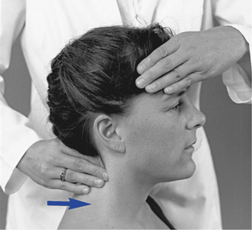
 Figure 5-57
In the supine position, the doctor assesses P-A glide by contacting the posterior joints with the palmar surfaces of the fingertips. The patient’s head rests on the table while the fingertips spring posteriorly to anteriorly against the articular pillars (Figure 5-58). Contact the posterolateral surface of adjacent vertebrae with the radial or palmar surface of the doctor’s index fingers to assess lateral-to-medial (L-M) glide. Testing is performed by springing toward the midline with one hand as the other hand counterstabilizes (Figure 5-59).
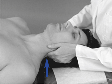
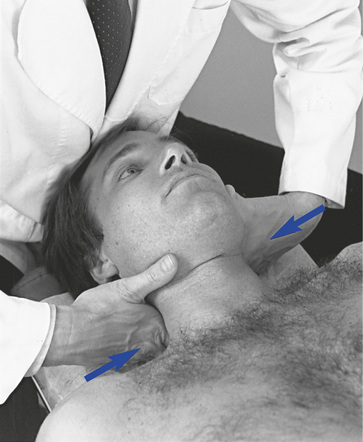
Figure 5-59 Supine joint play evaluation for lateral-to-medial glide. The doctor contacts adjacent levels and applies medial-to-lateral pressure with the cephalad hand as the caudad hand counterstabilizes.
During P-A JP assessment, the doctor should feel a subtle gliding and recoil at each segment tested. The movement should be uniform on each side and pain free; unilateral resistance or a tendency for the spine to rotate out of the sagittal plane may indicate segmental dysfunction. L-M glide is less giving than A-P glide, and a perceptible decrease in movement should be noted when the adjacent vertebra is counterstabilized. Excessive sponginess and lack of elastic resistance with either procedure indicates possible hypermobility or instability.
Segmental Range of Motion and End Play (C0–1) C0–1 Flexion and Extension
Atlanto-occipital flexion and extension may be evaluated by placing the tip of the index finger in the space between the mandibular ramus and the anterior tip of the atlas transverse process. The doctor’s IH supports the top of the head in the sitting position and cups the patient’s contralateral occiput and mastoid in the supine position. The patient’s chin is elevated and tucked to instill extension and flexion in the upper cervical spine. The space between the mandibular ramus and atlas transverse process opens during extension and closes during flexion (Figure 5-60). Fixation in this plane leads to a loss of rolling of the occiput on the atlas and unchanged spacing between the angle of the jaw and the atlas transverse process.
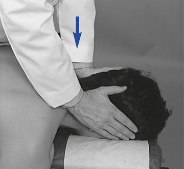
To evaluate end play, apply additional springing overpressure at the end ROM. For flexion, the contacts are established under the inferior rim of the occiput, with pressure applied upward. For extension, the contacts are established over the mastoid and posterior occiput, with pressure applied forward and downward (Figure 5-61). Flexion end play has a firmer quality because it is limited by the strong posterior neck muscles.
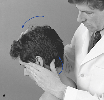
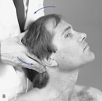
 Figure 5-61
C0–1 Rotation (P-A glide)
The index finger is placed between the mandibular ramus and the anterior tip of the atlas transverse process. The head is passively rotated away from the side of contact. The gap between the mandibular ramus and the atlas transverse process opens on the side opposite rotation and close on the side of rotation. Occipital rotation is limited and occurs at the end of cervical rotation (Figure 5-62).
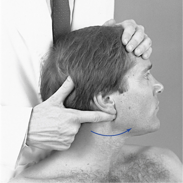
 Figure 5-62
C0–1 Lateral Flexion
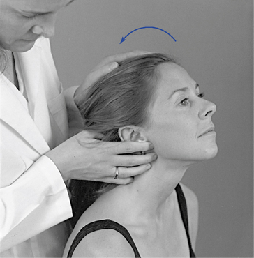
Lateral flexion is evaluated by placing the index finger between the inferior tip of the mastoid process and the atlas transverse process (Figure 5-63). This interspace is difficult to locate because of its small size and the overlying musculature. The head is laterally flexed away from the side of contact, and the gap between the mastoid and atlas transverse should open on the side opposite the lateral flexion. End play is evaluated on the side of lateral flexion for medial glide. To evaluate medial glide, the doctor contacts the posterior lateral aspect of the occiput with the lateral surface of the index finger (or fingertips of the index and middle fingers). The patient’s head is laterally flexed toward the side of contact while the doctor springs medially at the end ROM (Figure 5-64).
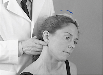
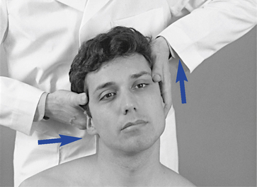
 Figure 5-64
Segmental Range of Motion and End Play (C1–2)
C1–2 Rotation (Posterior-to-Anterior Glide)
To evaluate atlantoaxial rotation, contact the posterior lateral aspect of the transverse process of the atlas and axis overlapping the C1–2 intertransverse space with the palmar surfaces of the middle and index fingers. The contacts are established on the side opposite cervical rotation, and the head is laterally flexed a few degrees toward the contact and passively rotated away from the side of contact (Figure 5-65). The doctor should palpate anterior rotation of C1 and separation of the C1–2 intertransverse space on the side opposite rotation (side of contact). At the end of passive rotation, evaluate end play by applying forward overpressure against the transverse process of C1. The atlantoaxial articulation lacks a strong interlaminar ligament and has a loose joint capsule, allowing for a comparatively flexible end play.
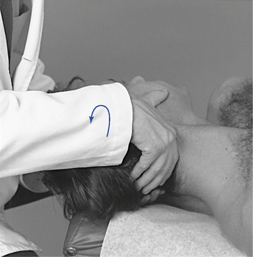
 Figure 5-65
C1–2 Medial Glide
Establish an index contact on the lateral surface of the atlas transverse process. The patient’s head is laterally flexed toward the side of contact while medial springing pressure is applied against the atlas transverse process (Figure 5-66). Lateral flexion at the atlas is limited; this procedure is designed to assess the small degree of medial glide that should be present, not the active range of lateral flexion.
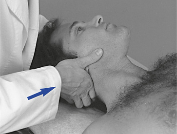
 Figure 5-66
C1–2 Flexion and Extension
Establish bilateral contacts over the C1–2 articulation. The structures are deep and difficult to directly palpate. They are identified by a sense of fullness through the soft tissues. Use the index and middle fingers on one side and a thumb contact on the other. The patient’s head is flexed and extended at the C1–2 articulation. Palpate for posteroinferior (PI) glide of the atlas during extension and AS glide during flexion (Figure 5-67). At the end of passive motion, evaluate end play by springing anterosuperiorly for flexion and anteroinferiorly for extension. The end play is elastic but firm compared with rotation end play.
Segmental Range of Motion and End Play (C2–C7)
The lower cervical spine may be evaluated with the patient in the sitting or supine position. In the sitting position, the doctor controls movement by contacting the patient’s forehead or the crown of the patient’s head. In the supine position, passive movement is controlled by cupping the patient’s contralateral occiput and mastoid.
Rotation (Posterior-to-Anterior Glide)
Evaluate movement by placing the palmar surface of the index or index and middle fingers over the articular pillars. With the patient in the sitting position, use either an upright (palm up) or reverse (palm down) hand contact method (Figure 5-68). Establish palpation contacts on the posterior surface of the articular pillars on the side opposite cervical rotation. The patient’s head is passively rotated away from the side of contact. The superior pillar should move forward relative to those below, and the soft tissues should elongate under the contact. With full rotation you should note a stair-stepping effect from the lower to upper cervical spine. At the end of passive motion, evaluate end play by springing from the posterior to the anterior, along the facet planes, normally encountering firm and elastic but giving end play.
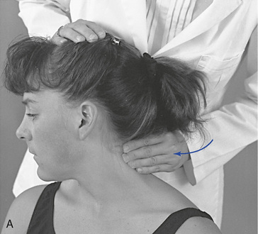
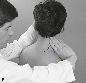
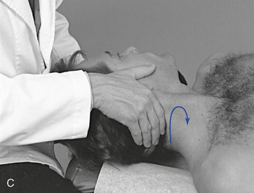
 Figure 5-68
Rotation (Anterior-to-Posterior Glide)
When evaluating this motion with the patient in the sitting position, stand behind the patient, opposite the side of contact. Establish a soft contact with the ventral surface of the index and middle fingers over the anterolateral (AL) surface of the articular pillars. Take care to avoid excessive pressure over the anterior neurovascular structures. The stabilization hand contacts the patient’s forehead or the top of the patient’s head. The patient’s head is laterally flexed away and rotated toward the side of contact to induce A-P gliding and gapping of the articulations under the area of contact. In addition to the A-P palpation vector (VEC), a slight inferior-to-superior (I-S) orientation should be maintained so that the palpation VEC is at a 90-degree angle to the facet plane (Figure 5-69). Evaluate end-play motion by springing from the anterior to the posterior along the same palpation VEC. You may also perform this method with the patient in the supine position by establishing a soft anterior lateral pillar contact with the thumb of your hand corresponding to the side of palpation (Figure 5-70).
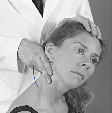
 Figure 5-69
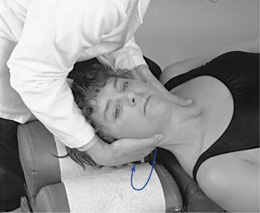
 Figure 5-70
C2–C7 Lateral Flexion
To assess lateral flexion, establish segmental contacts over the articular pillars slightly posterior to the midcoronal plane. If the contacts are placed too far anteriorly, they can become uncomfortable to the patient. Segmental contacts may be established unilateral or bilaterally. They may be established with the index and middle fingers of one or both hands or with the fingers and thumb of the same hand. When using unilateral fingertip contacts, stand to the side opposite the contact and change palpation hands and sides as you evaluate movement to each side (Figure 5-71). With the patient in the supine position, kneel at the head of the table and use bilateral fingertip or index contacts (Figure 5-72).
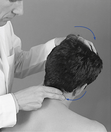
 Figure 5-71
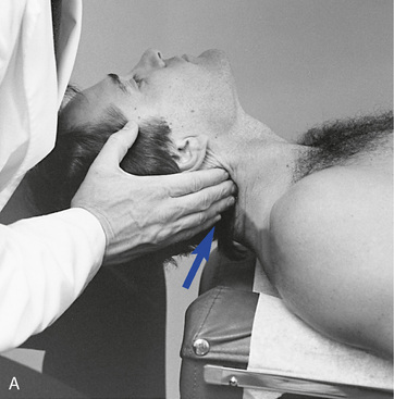
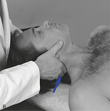
 Figure 5-72 Palpation of right lateral flexion of C5–C6 in the supine position with a fingertip contact (A) and an index contact (B) of the right C5–C6 articulation.
During the assessment of lateral flexion, palpate bending of the articular pillar on the side of lateral flexion and elongation of the soft tissues on the side opposite the lateral flexion (see Figure 5-71). At the end of passive motion, evaluate end play by applying additional overpressure by pushing toward the midline from the side of lateral flexion (concave toward convex). The VEC should incorporate an inferior inclination to avoid compressing the soft tissues. The end-play quality for lateral flexion is similar to that of rotation—firm but giving and elastic.
C2–C7 Flexion and Extension
To evaluate segmental flexion and extension, establish bilateral or unilateral contacts over the posterior articular pillars. Establish the segmental contacts with the fingertips or with the fingertips and thumb of the same hand (Figure 5-73). During extension, palpate PI gliding of the articular pillars. During flexion, palpate AS gliding of the articular pillars. Evaluate flexion end play by applying additional overpressure in an AS direction, and evaluate extension by applying additional overpressure through the palpation hand in an anterior direction. Extension movement is perceived as anterior glide and an increase in the cervical lordosis and flexion as posterior movement and reversal of cervical lordosis. The quality of end play for flexion is more resistant as a result of strong posterior neck muscles.
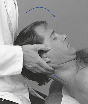
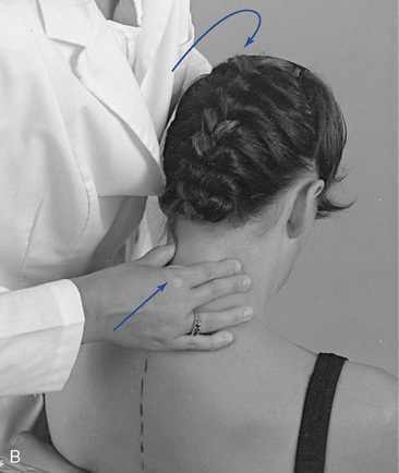
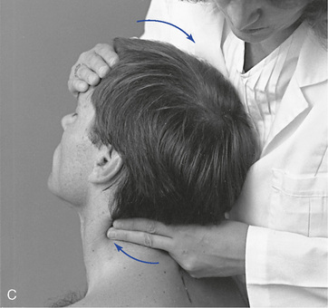
 Figure 5-73
 C, Palpation of cervical extension at the C3–4 articulation.
Overview of cervical spine adjustments
The cervical spine is flexible and composed of small structures. It is easy to overpower the neck, so caution must be used in the delivery of cervical adjustments. Adjustments of the cervical spine are performed with the patient in sitting, prone, and supine positions. Most techniques involve adjustive positions that produce movement of head and motion segments in the direction of joint restriction and adjustment. Therefore the majority of the adjustments presented (assisted methods) are applied to develop tension in the motion segments inferior to the level of segmental contact. Resisted methods are used less frequently. When resisted methods are applied, they are typically used in the treatment of rotational dysfunction. Resisted cervical or thoracocervical adjustments are applied to develop maximal tension in the motion segments superior to the level of established contact.
Rotational Dysfunction
Rotational dysfunction of the cervical spine has been postulated to result from loss of anterior glide of the facets on the side opposite the direction of rotation restriction (side of posterior body rotation) or posterior movement and gapping on the side of rotational restriction (Figure 5-74). The side and site of fixation is assessed by determining the side of subjective and palpable discomfort and comparing the end-play quality of P-A glide on one side to the A-P glide on the other.
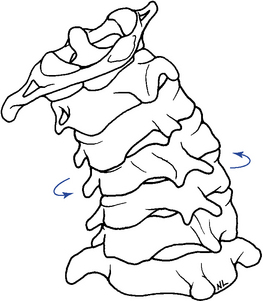
Figure 5-74 Posterior view of the cervical spine, illustrating left rotation characterized by anterosuperior glide of the right facet joints and posteroinferior glide of the left facet joints.
Dysfunction may be treated with assisted methods by contacting the posterior pillar of the superior vertebra on the side of posterior body rotation (side opposite the rotation restriction). In the lower cervical spine, the adjustive thrust would be directed anteriorly (Figure 5-75).
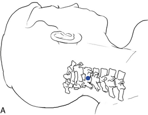
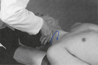
 Figure 5-75 Index contact applied to the right C3 articular pillar (dot), with adjustive force directed anterosuperiorly (arrow) to induce left rotation of the right C3–4 motion segment.
Methods directed at inducing posterior glide and gapping on the side of restricted rotation may be treated with either assisted or resisted methods. In both techniques, the cervical spine is laterally flexed away from the side of contact to lock the contralateral joints and distract the joint to be adjusted. With assisted methods, the contacts are established on the ipsilateral-anterolateral pillar of the superior vertebra on the side of rotational restriction (side opposite the posterior body rotation). The adjustive thrust is directed in a posterior direction (Figure 5-76). When resisted methods are applied, the contacts are established on the spinous process of the inferior vertebra on the side opposite the rotation restriction (inferior vertebra on the side of posterior body rotation). The adjustive thrust is directed medially through the spinous contact, resisted by the counter-rotational positioning of the patient’s head (Figure 5-77).
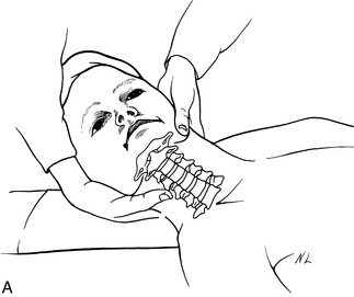
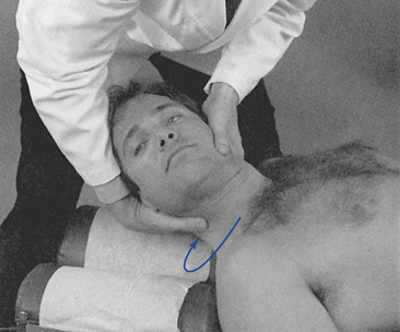
 Figure 5-76
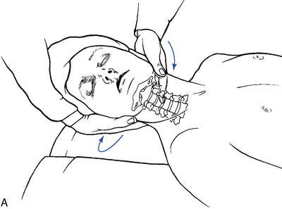
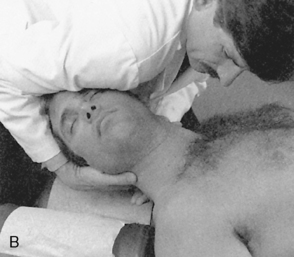
 Figure 5-77
Lateral Flexion Dysfunction
Lateral flexion dysfunction of the cervical spine may result from a loss of inferior glide and approximation of the joints on the side of lateral flexion dysfunction or a loss of contralateral superior glide on the side opposite lateral flexion restriction (Figure 5-78). The exception is the atlantoaxial articulation, which has horizontal facet planes and very limited lateral flexion. Determination of sites and direction of restriction are assessed by end feel evaluation.
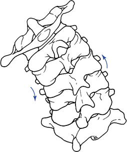
Figure 5-78 Posterior view of the cervical spine, illustrating left lateral flexion and superior glide of the right facet joints and inferior glide of the left facet joints.
Lateral flexion dysfunction is typically treated with assisted methods. In the lower cervical spine, lateral flexion is induced by contacting the articular pillar of the superior vertebrae on the side of lateral flexion restriction and applying adjustive thrusts medially and inferiorly along the facet planes (Figure 5-79, A). Techniques directed at inducing unilateral long-axis distraction of the posterior joints may also be applied to treat restrictions in lateral flexion by inducing distraction in the affected joints (Figure 5-79, B).
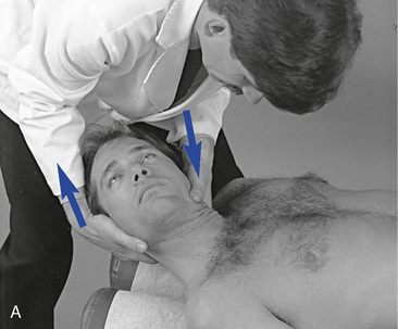
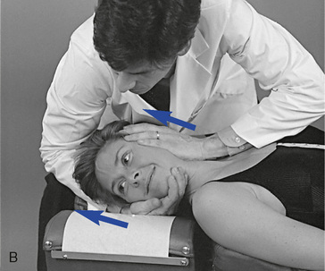
 Figure 5-79 A Index contact applied to the left posterolateral articular pillar of C3, with adjustive force directed medioinferiorly (arrow) to induce left lateral flexion of the C3–4 motion segment. B, Adjustment applied to induce long-axis distraction in the left C2–3 articulation.
Lateral flexion restrictions in the atlanto-occipital (C0–C1) joint are distinctive because of the unique anatomy. Methods applied to induce lateral flexion movement in C0–C1 can be applied with contacts established on the ipsilateral or contralateral side of lateral flexion restriction (Figure 5-80, A–C).
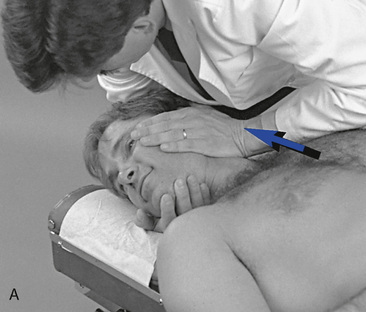
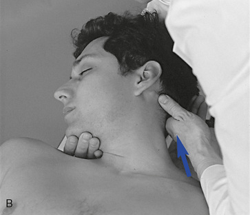
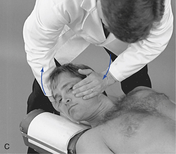
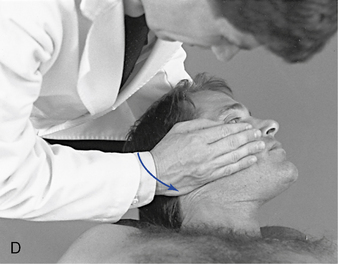
 Figure 5-80 A, Hypothenar contact applied to the left inferior aspect of the occiput to distract the left atlanto-occipital articulation. B, Thumb contact applied to the left inferior aspect of the occiput to distract the left atlantooccipital articulation. C, Hypothenar contact applied to the left lateral aspect of the occiput to induce left lateral flexion of C0–C1. D, Hypothenar contact applied to the right inferior aspect of the occiput to extend the C0–C1 articulation.
Flexion and Extension Dysfunction
Flexion restrictions (extension malpositions) may be treated with methods that induce gliding distraction in the facet joints. Many of the methods described for treating lateral flexion restrictions and rotational restrictions induce movements that may effectively induce this movement. Adjustments that induce long-axis distraction may also alleviate restrictions in flexion by inducing joint distraction (see Figure 5-79, B). Prone methods are also described for cervical flexion restrictions (Figure 5-81, A) but it is questionable whether segmental flexion can be induced with a prone stationary position and a posterior to anterior thrust.
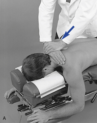
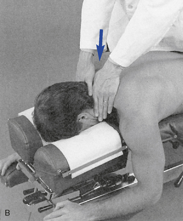
Figure 5-81 A, Adjustment applied to midcervical spine to induce flexion with a posterior-to-anterior (P-A) and inferior-to-superior (I-S) vector. B, Adjustment applied to midcervical spine to induce extension with P-A vector.
Cervical extension induces motion that stretches the capsule and its periarticular tissue in directions not specifically addressed with rotation or lateral flexion adjustments. Therefore, extension restrictions (flexion malpositions) are more effectively addressed by adjustive techniques and VECs directed specifically for this dysfunction. When applying prone methods establish contacts in the midline over the spinous process or both articular pillars (see Figure 5-81, B), prestress the joint into extension and deliver a thrust anteriorly. When applying extension adjustments, use extreme caution to avoid excessive extension and joint compression. The thrust must be shallow and gentle.
Atlanto-occipital restrictions in flexion (extension malposition) are treated with methods directed at inducing posterosuperior glide or long-axis distraction of the occipital condyle (Figure 5-80, A and B). Restrictions in extension (flexion malposition) are treated with methods directed at inducing anteroinferior glide of the occipital condyle (Figure 5-80, D). The thrust is directed mainly in the sagittal plane, with limited cervical rotation and some segmental lateral flexion to isolate the joint.
All adjustive techniques described in Chapters 5 and 6 are structured around the abbreviations and symbols presented in Box 5-3. The adjustive techniques in this chapter have been given names that are based on the involved joint or region, patient position, contact used by the clinician, body part contacted, and any necessary additional information (e.g., push, pull, with distraction, etc.), as well as the induced joint movement. These names follow the patterns used by the U.S. National Board of Chiropractic Examiners and are designed to be helpful in the teaching and testing for competence of the procedures (see Boxes 5-4-5-10).
Upper cervical spine adjustments (BOX 5-4)
Supine
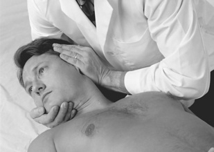
Figure 5-82 Hypothenar contact applied to the left inferior aspect of the occiput to flex or distract the left atlanto-occipital articulation.
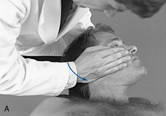
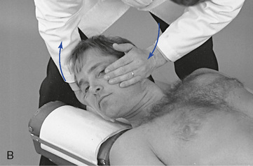
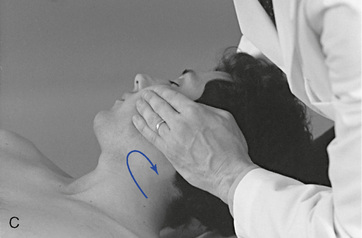
 Figure 5-83 A, Hypothenar contact applied to the right inferior aspect of the occiput to extend the C0–1 motion segment. B, Hypothenar contact applied to the left lateral aspect of the occiput to left laterally flex the C0–1 motion segment. C, Hypothenar contact applied to the left posterolateral aspect of the occiput to right rotate the left C0–1 motion segment.
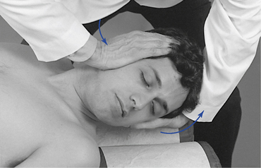
Figure 5-84 Hypothenar (calcaneal) contact applied over the right zygomatic arch to right laterally flex the atlanto-occipital motion segment.
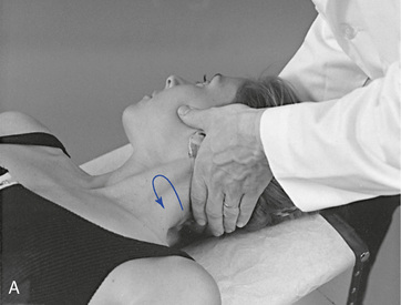
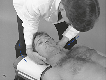
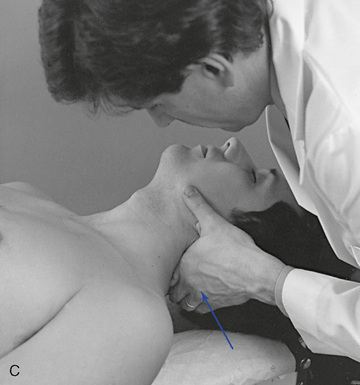
 Figure 5-85 A, Index contact applied to the left atlas transverse process to right rotate the C1–2 motion segment. B, Index contact applied to the left atlas transverse process to left laterally flex the C1–2 motion segment. C, Index contact applied to the posterior aspect of the left atlas transverse process to extend the left C1–2 motion segment.
Sitting
Figure 5-86 Bilateral calcaneal zygoma contacts applied to the zygomatic arches to induce flexion in the C0–1 motion segment.
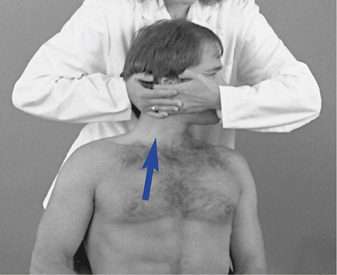
 Figure 5-87 Middle finger contact applied to the right lateral and inferior aspect of the occiput to distract the right atlanto-occipital articulation.
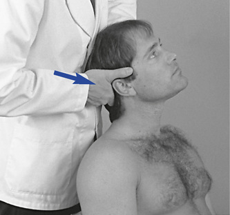
 Figure 5-88 Index contact applied to the right posterior and inferior aspect of the occiput to extend the atlanto-occipital motion segment.
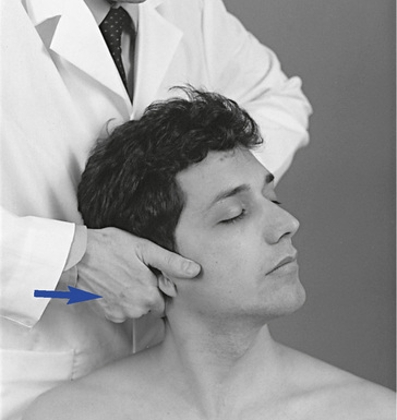
 Figure 5-89 Index contact applied to the posterior aspect of the right transverse process of the atlas to induce left rotation at C1–2.
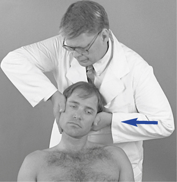
 Figure 5-90
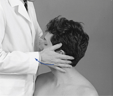
 Figure 5-91
Prone
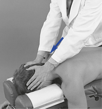
Figure 5-92 Bilateral thenar contacts applied to the posteroinferior aspect of the occiput to flex the atlanto-occipital motion segment.
Lower cervical spine adjustments (BOX 5-5)
Supine
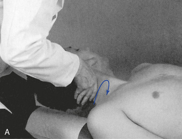
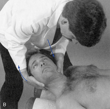
 Figure 5-94 A, Index contact applied to the posterior aspect of the right C2 articular pillar to induce left rotation of C2–3. B, Index contact applied to the lateral aspect of the C3 articular pillar to left laterally flex C3–4.

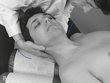
 Figure 5-95 A, Index contact applied to the lateral aspect of the C6 spinous process to left rotate. B, Index contact applied to the left lateral aspect of the C6 spinous process to left rotate and/or to left laterally flex the C6–7 motion segment. C, Resisted method. Index contact applied to the left lateral aspect of the C6 spinous process to right rotate the C6–7 motion segment.
Rotational dysfunction may also be treated with resisted methods. The resisted adjustive approach is designed to induce rotation and gapping in the facet joint contralateral and superior to the side of adjustive contact. When a resisted method is used, the adjustive contact is established on the lateral surface of the spinous process of the inferior vertebra on the side opposite the rotation restriction. Preadjustive tension is developed by rotating the neck in the direction of restriction as counterpressure is applied against the spinous process. Lateral flexion is also induced toward the side of contact to distract the contralateral facet joints and block the ipsilateral facet joints (Figure 5-95, C). To deliver the impulse, counterthrust with both hands. The contact hand thrusts medially by inducing adduction of the shoulder. The IH induces counter-rotation by supinating the forearm.
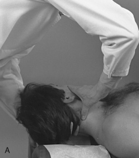
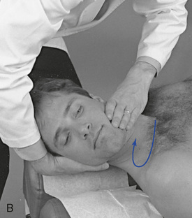
 Figure 5-96 Thumb pillar posterior technique. A, Thumb contact applied to the posterior aspect of the right C3 articular pillar. B, Procedure shown from the other side, illustrating the treatment of a right rotation restriction at C3–4.
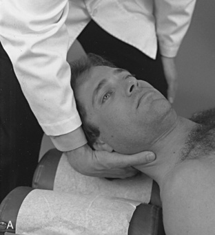
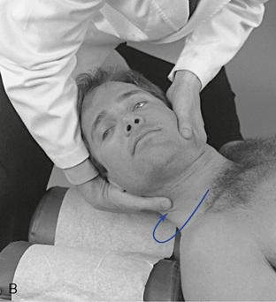
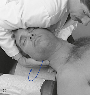
 Figure 5-97 Thumb pillar anterior technique. A, Thumb contact applied over the anterolateral aspect of the right C2 articularpillar. B, Demonstration of procedure in the treatment of a right rotation restriction, applied to induce gapping in the right C2–3 articulation. C, Counterthrust technique, with contacts applied to the anterolateral aspect of the right C2 articular pillar and the left lateral aspect of the C3 spinous process. Note support for contacts with the doctor’s shoulder.
This adjustment may be combined with the index spinous adjustment to induce a counter thrust (push/pull). In this scenario, the IH contacts the spinous process of the lower vertebrae on the contralateral side. At tension, both hands thrust toward the midline to induce counter-rotation (Figure 5-97, C).
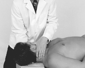
Figure 5-98 Index contact applied to the right articular pillar of C4 to induce left rotation in the C4–5 motion segment.
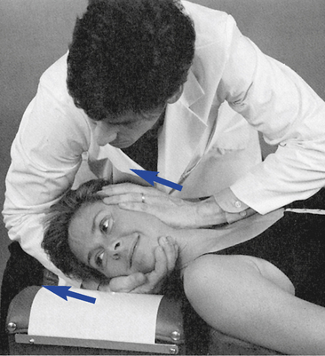
Sitting
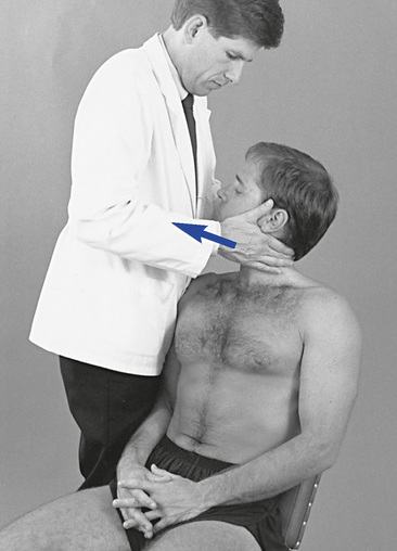
 Figure 5-100 Digital contact applied to the left C4 articular pillar to right rotate the C4–5 motion segment.
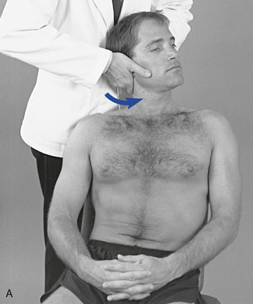
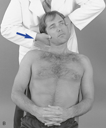
 Figure 5-101 A, Index contact applied to the right articular pillar to left rotate the C3–4 motion segment. B, Index contact applied to the right lateral aspect of the C3 articular pillar to right laterally flex the C3–4 motion segment.
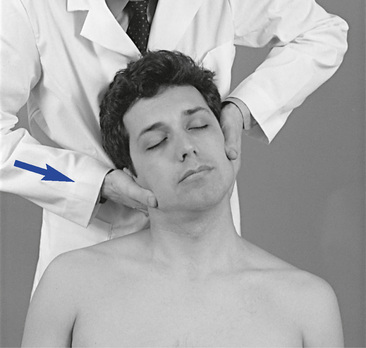
Figure 5-102 Index contact applied to the right lateral aspect of the C4 spinous process to right laterally flex or right rotate the C4–5 motion segment.
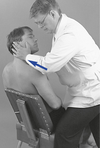
 Figure 5-103
Prone
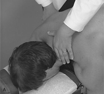
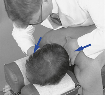
 Figure 5-104 Index pillar prone technique. A, Index contact established over the posterior aspect of the left C5 articular process. B, Procedure shown to induce left lateral flexion and right rotate at the left C5–6 motion segment.
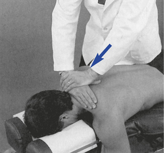
When treating extension dysfunction, position the patient’s cervical spine in a slightly extended position and center your body over the contact. Extension is induced by delivering an impulse thrust anteriorly. When performing this adjustment, use extra caution to avoid excessive depth and hyperextension of the neck.
These adjustments can be performed on a drop table. A drop mechanism that allows downward and forward movement may provide a mechanical advantage over a straight downward drop by minimizing the compression and providing axial distraction.
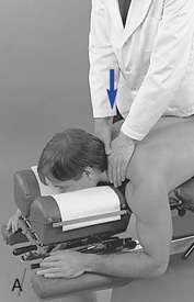
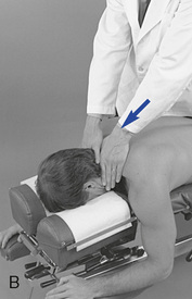
Figure 5-106 Bilateral index contacts established over the posterior aspect of the C4 articular pillars to extend (A) or flex (B) the C4–5 motion segment.
When treating extension dysfunction, position the patient’s cervical spine in a slightly extended position and center your body over the contact. Extension is induced by delivering an impulse thrust anteriorly. When performing this adjustment, use extra caution to avoid excessive depth and hyperextension of the neck.
These adjustments can be performed on a drop table. A drop mechanism that allows downward and forward movement may provide a mechanical advantage over a straight downward drop by minimizing the compression and providing axial distraction.
Thoracic spine
In the thoracic spine, protection and function of the thoracic viscera take precedence over intersegmental spinal mobility. Although the limiting anatomic structures make the thoracic spine the least mobile part of the spinal column, the small movements that do occur within the functional units are still significant. Although more clinical attention has been focused around the cervical and lumbar regions, the thoracic region is an area that must be considered important because of the possible mechanical changes that may result in effects to the elements of the autonomic nervous system. Furthermore, the addition of the articulations for the ribs makes the thoracic region an exceptional structure. Finally, this region seems to be prone to chronic postural problems affecting sections of the thoracic spine and the supporting soft tissues (myofascial pain syndromes).
Functional anatomy
The body of the typical thoracic vertebra (T2–T8) is heart-shaped, with both the A-P and side-to-side dimensions of equal length (Figure 5-107). The anterior surface of the body is convex from side to side, and the posterior surface is deeply concave. Both the superior and inferior surfaces of the body are flat, with a ring around the margin for attachment of the IVD. The pedicles of thoracic vertebrae are short and have inferior vertebral notches deeper and larger than in any other part of the spine. The laminae are short, broad, thick, and overlapping. The spinous processes are long and slender, with a triangular shape in cross-section. They point obliquely downward, overlapping in the midthoracic spine and limiting extension movement. The transverse processes arise from behind the superior articular processes. They are thick, strong, and relatively long, with a concave facet on the anterior side. The intervertebral foramina in this region are essentially circular in shape and fairly small when compared with other areas of the spine (see Figure 5-107).
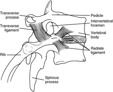
The articular facets form an angle of approximately 60 degrees from the transverse toward the coronal plane and 20 degrees from the coronal toward the sagittal plane (Figure 5-108). The inferior articular process arises from the laminae to face inferomedioanteriorly. The superior articular process arises from near the lamina-pedicle junction to face superolaterally and posteriorly. The inferior articular process lies posterior to the superior articular process of the vertebra below.
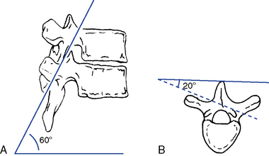
The IVDs are comparatively shallow in the thoracic spine. The disc height–to–body height ratio is 1:5, making it the smallest ratio in the spine (Figure 5-109). This low ratio contributes to the decreased flexibility of the thoracic spine. The nucleus is also more centrally located within the annulus of the thoracic disc than it is in either of the other two spinal regions.
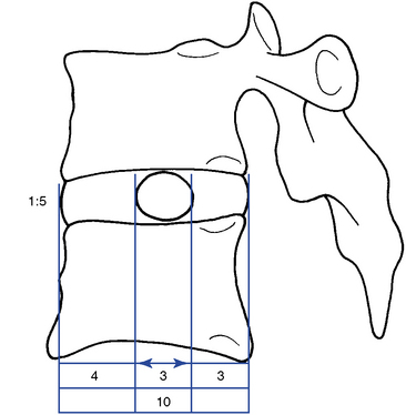
Figure 5-109 The location of the nucleus and the disc height–to–body height ratio in the thoracic spine.
One special feature of thoracic vertebrae is the presence of costovertebral and costotransverse joints, which form the articulations for the ribs (see Figure 5-107). The costovertebral joints (demifacets) are located on either side of the vertebral body to form an articulation with the heads of the ribs. The costotransverse joints are located on the anterior aspects of the transverse processes to articulate with the tubercles of the ribs.
The thoracic atypical vertebrae include T1 and T9 to T12 (Figure 5-110). The vertebral body of T1 resembles that of C7 and possesses a whole facet for articulation with the first rib. The T9 vertebra may have no demifacets below, or it may have two demifacets on either side (in which case, the T10 vertebra will have demifacets only at the superior aspect). T10 has one full rib facet located partly on the body of the vertebra and partly on the tubercle. The T11 segment has complete costal facets, but no facets on the transverse processes for the rib tubercle. This vertebra also begins to take on characteristics of a lumbar vertebra. The spinous process is short and almost completely horizontal. T12 has complete facets on the vertebra for articulation with the ribs, but otherwise resembles a lumbar vertebra. The inferior articulating surfaces of T12 are convex and are directed laterally and anteriorly in the sagittal plane, like those in the lumbar spine. Superior, inferior, and lateral tubercles (see Figure 5-110) replace the transverse processes.
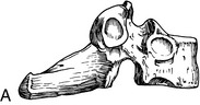
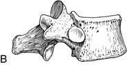
Thoracic curve
The thoracic spine forms a kyphotic curve of less than 55 degrees,18 with an accepted range of 20 to 50 degrees19,20 and an average of 45 degrees6 (Figure 5-111). It is a structural curve present from birth and maintained by the wedge-shaped vertebral bodies that are approximately 2 mm higher posteriorly. The thoracic curve begins at T1–2 and extends down to T12, with the T6–7 disc space as the apex.21
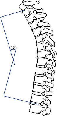
Alterations in the thoracic curve can be anatomic or postural. A change in the primary thoracic curve is likely to produce a change in the secondary curves in the cervical and lumbar spine. The lumbar curve tends to increase, and the cervical curve decreases or shifts forward, creating a cervical “poking” posture. This postural syndrome of forward head positioning and rounded and forward shoulders is often associated with chronic stretch weakness of the middle and lower trapezius muscles. The chronic strain to the posterior back and neck muscles can induce local myofascial pain syndromes and headaches.22 As the thoracic kyphosis increases, it crowds the thoracic viscera, interfering with normal physiologic functioning.
Juvenile kyphosis (Scheuermann disease) and osteoporosis also result in an increased thoracic kyphosis. In juvenile kyphosis the wedge shape of the vertebral body is exaggerated, but the cause remains inconclusive. Theories of the pathogenesis include aseptic necrosis, endplate fracture, infection, endocrine abnormalities, trabecular deficiencies, vitamin deficiencies, fluoride toxicity, and mechanical factors.23
Osteoporosis reduces the number and size of trabeculae in the vertebral body, diminishing the axial loading stretch and resulting in compression fractures, which accentuate the kyphotic curve. Dietary deficiencies, malabsorption syndromes, steroid use, and endocrine disorders have been implicated as causal factors of osteoporosis.24
Range and patterns of motion
Of the three cardinal planes of movement, sagittal plane movement of flexion and extension is the most restricted. Rotation and lateral flexion demonstrate nearly equal movement, with each exhibiting nearly twice as much movement as flexion and extension (Table 5-4; see Figure 5-24).
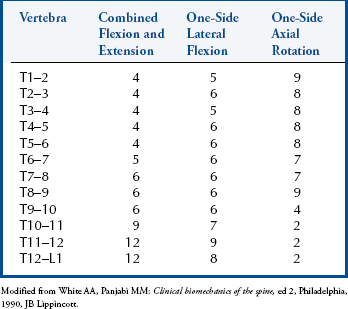
Movement in the upper thoracic spine is generally less than in the lower. The exception is rotation, which decreases dramatically in the lower thoracic segments as the facet facings become more sagittal.5 The instantaneous axis of movement for the thoracic spine, like other spinal regions, remains somewhat tentative.25 Using fresh cadaveric specimens, Panjabi and associates25 determined the likely sites for flexion and extension, lateral flexion, and rotation (Figure 5-112).