15 THE NEONATAL CXR
The newborn infant in respiratory distress is an emergency.
 CXR essential (1). A fundamental principle—as a rule the neonatologist cannot be absolutely certain of the cause of the distress without a CXR. The CXR will usually confirm the default diagnosis or reveal the true cause. CXR essential (2). Many of these infants will eventually have various lines and tubes inserted. Confirmation of correct positioning requires a CXR.
Respiratory distress in the newborn will occasionally be due to serious anatomical anomalies that usually require surgical intervention1,2. These include: oesophageal atresia/tracheo-oesophageal fistula; diaphragmatic hernia; cystic adenomatoid malformation of the lung; congenital lobar emphysema.
All of these are very rare conditions, but they must not be overlooked. If they are not recognised then morbidity and mortality will be high. These uncommon abnormalities will not be described here. Radiographic examples are illustrated on p. 213. In this chapter we will concentrate on the common day-in, day-out CXR problems encountered in the neonatal intensive care unit (NICU).
THE LUNGS
TERM INFANTS
Transient Tachypnoea of the Newborn (TTN)1–5
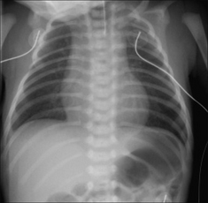
TTN occurs most commonly in pre-term infants following Caesarean section. All the same, TTN can occur in term infants. Sometimes referred to as wet lung, because the fluid that filled the lungs prior to birth has not been cleared completely. Following delivery the infant breathes with some difficulty and requires oxygen. The CXR shows indistinct pulmonary vessels bilaterally. There is lack of a sharp margin to the heart, mediastinum and diaphragm (Fig. 15.2). The lungs remain well inflated. Sometimes there is fluid in the horizontal fissure; occasionally some pleural fluid elsewhere.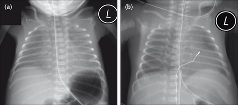
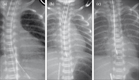
Figure 15.2 Neonate. Slight respiratory distress. CXR (a) at age one day. Indistinct pulmonary vessels. Slightly indistinct margins of the heart and diaphragm. CXR (b) at age two days. The lungs are clear. Cardiac and diaphragm margins are sharp. The original CXR appearances were due to TTN (wet lung). Note that the umbilical vein catheter (UVC) is incorrectly positioned (see p. 216).
PRE-TERM INFANTS
Respiratory distress syndrome/hyaline membrane disease (HMD)1-5
HMD is not simply due to surfactant deficiency. It represents an acute injury of immature lungs. One aspect of this immaturity is surfactant deficiency. HMD affects mainly very pre-term infants. It can occur in term infants after Caesarean section and also when the mother is diabetic. Note: HMD and TTN are not always distinct and separate entities. They can overlap. All pre-term infants will have some degree of TTN. CXR appearances:
These will be affected by the amount of lung distension produced by the assisted ventilation. The following are some useful generalisations.
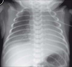
The lungs show a homogeneous, bilateral, ground glass appearance (Fig. 15.3). Sometimes lung consolidation (i.e. airspace shadowing) also occurs.
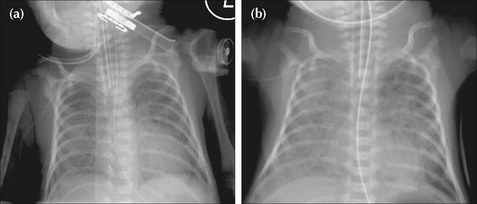
Figure 15.3 Pre-term infant. Respiratory distress. CXR (a) at age one day. Ground glass appearance in both lungs. CXR (b) at age three days. Confluent airspace shadowing in both lungs. HMD. CXR (a) represents the typical early findings in HMD and CXR (b) shows the typical appearances that occur within a day or two.
The lungs become consolidated as a result of a profuse exudation of fluid into the alveoli. They appear opaque. Frequently there are air bronchograms (see p. 227). A complete white out of both lungs may occur.
Severe HMD requires assisted respiration either with ventilation or with continuous positive airway pressure (CPAP). Complications may then result, either from lung pathology or from the treatment which is keeping the baby alive…or from both the pathological process and the treatment.
Early complications include: pneumothorax, tension pneumothorax, pulmonary interstitial emphysema (PIE), and mediastinal emphysema2,6. These complications are usually short term, but some will be fatal if not recognised and treated (Figs 15.4 and 15.7).
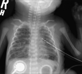
Figure 15.4 Pre-term infant. Age five days. Respiratory distress. HMD and a complicating left pneumothorax has been treated with an intercostal drain. The bubbly appearance in both lungs represents air that has passed through ruptured alveolar walls and dissected through the interstitial tissues. This complication represents pulmonary interstitial emphysema (PIE).
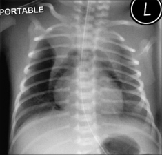
Figure 15.7 Pre-term infant. HMD. Pneumomediastinum. The air has arisen from an alveolar leak, dissected through the lung interstitium, and then entered the mediastinum. The normal thymus is outlined by the mediastinal air—a peculiar but characteristic appearance. It is often referred to as the angel wing sign.
Lung changes develop and persist in some infants (Fig. 15.8). The appearance is referred to as chronic lung disease (CLD) of prematurity…a synonym for the more traditional term of bronchopulmonary dysplasia.
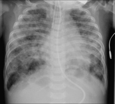
Figure 15.8 Age five months. Previous HMD. The ring shadows and the coarse interstitial shadows are indicative of CLD of prematurity. Incidentally, the endotracheal tube (ETT) is too low; it is just above the carina.
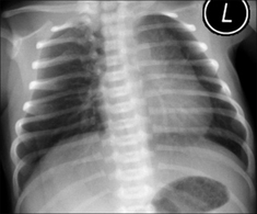
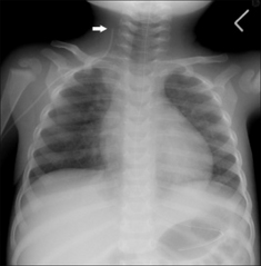
Figure 15.5 Be careful. Neonate. Normal CXR. Two features could lead to erroneous diagnosis. (1) The infant is rotated to the left and the rotation distorts the mediastinal appearance. (2) A skin crease accounts for the line artefact overlying the right lung base. Vessels can be seen outside this line—i.e. it is not a pneumothorax.
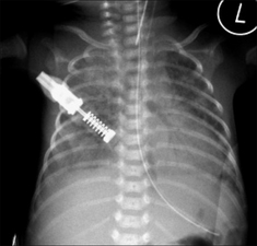
Figure 15.6 Pre-term infant. HMD. An air bronchogram (see p. 227) is present in the consolidated left lung. Air bronchograms are often seen in lungs affected by HMD. There is no particular clinical connotation when an air bronchogram is present in HMD.
WATCH OUT FOR A PNEUMOTHORAX
A pneumothorax must be excluded on every single CXR. It is a common problem and it may produce a subtle change on the CXR.
Much tougher
Subtle features on the supine CXR (Fig. 15.9) may be overlooked. These are described on pp. 97–99. The air in the pleural space may show:
Really dangerous
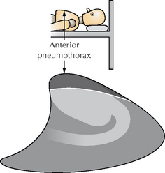
Figure 15.9 In the NICU the CXR is obtained with the infant supine. Air in the pleural space will collect at the highest point, i.e. anteriorly, as shown on this lateral perspective of the thorax.
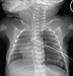
Figure 15.10 Supine CXR. HMD. Extensive lung shadowing. Complicating pneumothorax… features to note: the sharp black line outlining the left heart border; the extreme clarity of the left dome of the diaphragm. Incidentally, the UVC tip is in the right atrium and the ETT is very low.
Tension pneumothorax. The CXR findings are described on pp. 100–102. Two cardinal features:
 The dome of the diaphragm on the affected side is almost always depressed or flattened (Fig. 15.11). Potential pitfall: With the baby lying supine the intrapleural air may collect anteriorly and a tension pneumothorax may compress and push the mediastinum in a posterior rather than in a lateral direction. Sometimes an anterior tension pneumothorax will only be revealed by a horizontal beam (i.e. a cross-table) CXR. Fig. 15.9 illustrates how an anterior tension pneumothorax can occur and be overlooked.
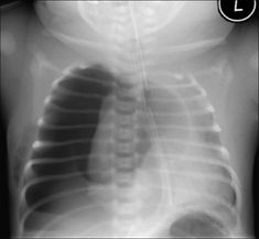
SOME RARE CONDITIONS CAUSING NEONATAL DISTRESS1,2
This chapter has concentrated on the everyday causes of neonatal distress. There are rare conditions that must not be overlooked. Four of these are illustrated below. The CXR is invaluable in suggesting the diagnosis.
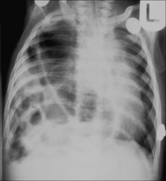
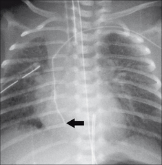
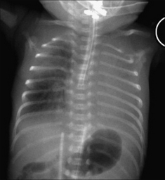
Figure 15.13 Severe respiratory distress. The ring shadows at the right base represent multiple loops of bowel. Diaphragmatic hernia1.
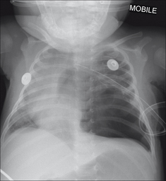
Figure 15.14 Be careful. The left lower zone lucency is not a pneumothorax, but is due to congenital cystic adenomatoid malformation of the lung (CCAM)1.
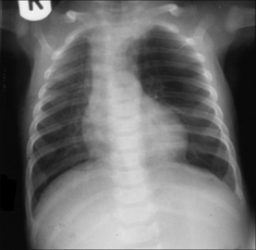
Figure 15.15 Neonatal distress. Abnormal left upper zone—very lucent and few vessels identified. Congenital lobar emphysema. See p. 203 for a brief summary of this condition.
TUBES AND LINES1,2,7–15
Various tubes and lines are used to monitor, ventilate, hydrate and feed infants in the NICU (Table 15.1).
Table 15.1 The various tubes and lines.
| Tube/line | Purpose |
|---|---|
| Umbilical vein catheter | |
| Umbilical artery catheter | |
| Central venous catheter | |
| Endotracheal tube | |
| Nasal prongs for continuous positive airway pressure | |
| Naso/orogastric tube | |
| Jejunal feeding tube |
UMBILICAL CATHETERS1,7–9,11–14
Basic post-natal anatomy
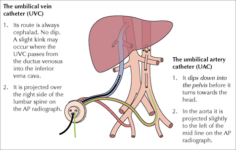
The single umbilical vein passes cephalad in the free margin of the falciform ligament just to the right of the mid line. The vein then divides into two branches (Fig. 15.17). One branch joins with the portal vein; the other continues as the ductus venosus (DV), terminating in the left (or middle) hepatic vein which joins the inferior vena cava. The length of the DV is approx. 2 cm in full-term infants; it is much shorter in tiny pre-term babies. Each umbilical artery dips downwards into the pelvis to enter the internal iliac artery (Fig. 15.18).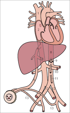
Umbilical Vein Catheter (UVC)1,2,8,9,11,14
Post-natal patency. The vein may be catheterised up to four days after birth. Eventually the vein closes, constricts, and forms the ligamentum teres extending from the umbilicus to the liver. The mesentery which surrounds the umbilical vein becomes the falciform ligament. Catheter tip: optimum position (Figs 15.19a and 15.20).
The requirement: the tip must be placed in a region of good blood flow and well away from branches that drain vital organs.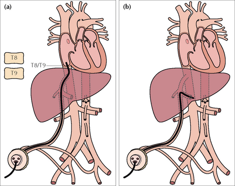
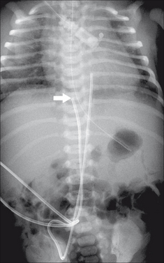
Figure 15.19 UVC catheter tip. (a) In good position. In the inferior vena cava just below the right atrium. A tip positioned at the level of T8–T9 vertebrae is usually satisfactory.(b) The tip has entered the portal vein; thrombosis is a recognised complication.
 Wrong position…potential complications
Umbilical Artery Catheter (UAC)1,2,7,9,11-13
Post-natal patency. The paired umbilical arteries constrict and obliterate two to five days after birth. The obliterated arteries are covered with peritoneum and will persist as fibrous cords in the anterior abdominal wall outside the peritoneum—these are the medial umbilical ligaments. Catheter tip: optimum position. Two choices (Fig. 15.22 and Table 15.2).
The requirement is that the tip is situated in a region of rapid blood flow and well away from the origin of vessels supplying the vital organs. A high position ensures that the tip of the UAC is well above the origins of the coeliac axis (T12), the superior mesenteric artery (T12–L1), and the renal arteries (L1–L2).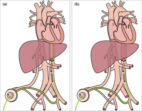
Figure 15.22 UAC catheters in good positions. (a) High position. Tip in the aorta just above the level of the dome of the diaphragm. (b) Low position. Tip in the aorta at approximately the level of L3/L4 vertebrae.
Table 15.2 UAC tip preferred position — two choices.
| Position high (preferred by most units) | Position low |
|---|---|
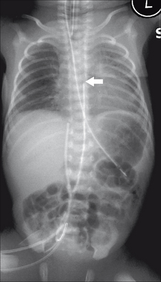
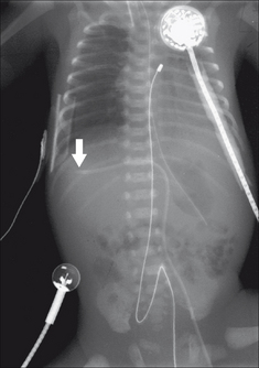
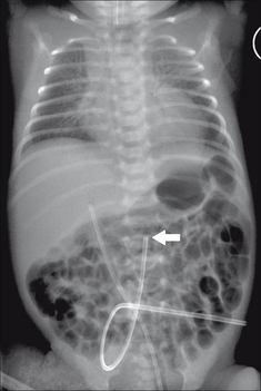
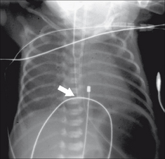
Figure 15.23 UAC in good (high) position. The tip (arrow) lies above the dome of the diaphragm (at the level of the T7 vertebra). (Retouched.)
CENTRAL VENOUS CATHETER—A LONG LINE
If introduced via a subclavian, internal jugular or antecubital approach—the tip should lie in the superior vena cava just above the right atrium(Fig. 15.25). If a femoral approach is used—the tip should lie just below the right atrium outside the heart (guideline: at the level of T8–T9 vertebrae). If the position of the tip is uncertain then it can be checked by introducing contrast medium into the catheter, or by ultrasound examination. Many units carry out this check as a routine practice.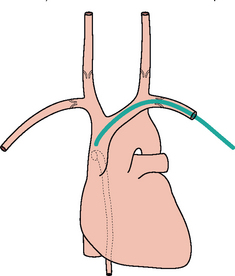
Figure 15.25 Central line. Good position with the tip in the superior vena cava well beyond the last valve in the subclavian vein. The position of the last valve in each internal jugular vein is also shown. The dotted vessel is the azygos vein draining into the superior vena cava.
ENDOTRACHEAL TUBE (ETT)12
Optimum position of the tip is in the mid trachea…i.e. above the carina and below the vocal cords (Fig. 15.28). ETT rules of thumb:
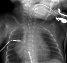
Figure 15.28 ETT. Satisfactory position. Incidentally, note that the UVC tip is in the right atrium.
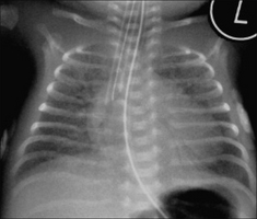
Figure 15.29 HMD. The ETT has entered the right main bronchus. Lung collapse has not yet occurred. The ETT was pulled back to achieve a satisfactory position.
FEEDING TUBES
Nasogastric (NG) tube10,12
Wrong positions for the tip (Fig. 15.32):
Jejunal feeding tube
Optimum position of the tip is in the fourth part of the duodenum (i.e. the tube has crossed the midline on the abdominal radiograph…from right to left).
Table 15.4 Checking the NG tube — three questions and three rules.
| Question 1: | Is the tip in the stomach? |
| If not… | |
| Question 2: | Is it curled up in the oesophagus? |
| If not… | |
| Question 3: | Has it passed into the larynx and entered the trachea or a bronchus? |
| Rule 1: | If the tip cannot be positioned in the stomach — oesophageal atresia needs to be excluded. |
| Rule 2: | If the tube passes below the diaphragm but the tip is seen to be projected over the thorax (i.e. not over the abdomen) and away from the oesophagus — a diaphragmatic hernia needs to be excluded. |
| Rule 3: | Think perforation. Although perforation is very much rarer than incorrect positioning in the bronchus, its clinical importance means that perforation must be considered whenever there is any deviation of the NG tube from the normal anatomical course through the oesophagus. |
OTHER EQUIPMENT/MONITORING DEVICES
Assorted monitoring devices may produce shadows on the CXR (Fig. 15.33). These include:
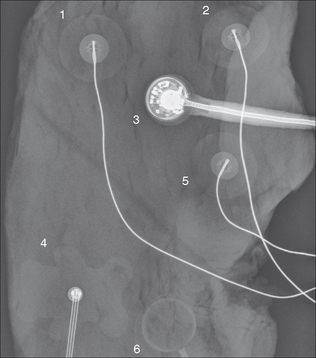
Figure 15.33 Various external monitoring devices will produce shadows on the CXR. Their precise appearance will vary between different countries and between different units. Several of these devices were placed on a piece of steak—to simulate the chest wall soft tissues—and a radiograph obtained.
Answer to Fig. 15.1 on p. 206:
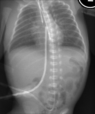
Figure 15.1 Neonate. Can you list the abnormal findings on this chest and abdominal radiograph? Answer on p. 224.
NB: some of the tubes and lines were retouched to make their positions clearer.
1. Wood BP. The newborn chest. Radiol Clin North Am. 1993;31:667-676.
2. Gibson AT, Steiner GM. Imaging the neonatal chest. Clin Radiol. 1997;52:172-186.
3. Fraser J, Walls M, McGuire W. Respiratory complications of preterm birth. BMJ. 2004;329:962-965.
4. Swischuk LE, John SD. Immature lung problems: can our nomenclature be more specific? AJR. 1996;166:917-918.
5. Northway WH. Bronchopulmonary dysplasia: twenty five years later. Commentary. Pediatrics. 1992;89:969-973.
6. Burt TB, Lester PD. Neonatal pneumopericardium. Radiology. 1982;142:81-84.
7. Dyer C. Is inexperience a defence against negligence? BMJ. 1986;293:497-498.
8. Kim JH, Lee YS, Kim SH, et al. Does umbilical vein catheterization lead to portal venous thrombosis? Prospective US evaluation in 100 neonates. Radiology. 2001;219:645-650.
9. Weber AL, DeLuca S, Shannon DC. Normal and abnormal position of the umbilical artery and venous catheter on the roentgenogram and review of complications. AJR. 1974;120:361-367.
10. Grunebaum M, Horodniceanu C, Wilunsky E, et al. Iatrogenic transmural perforation of the oesophagus in the preterm infant. Clin Rad. 1980;31:257-261.
11. Hogan MJ. Neonatal vascular catheters and their complications. Radiol Clin North Am. 1999;37:1109-1125.
12. Cohen MD. Tubes, wires, and the neonate. Clin Radiol. 1980;31:249-256.
13. Greenough A. Where should the umbilical catheter go? Lancet. 1993;341:1186-1187.
14. Raval NC, Gonzalez E, Bhat AM, et al. Umbilical venous catheters: evaluation of radiographs to determine position and associated complications of malpositioned umbilical venous catheters. Am J Perinatol. 1995;12:201-204.
15. Das Narla L, Hom M, Lofland GK, et al. Evaluation of umbilical catheter and tube placement in premature infants. Radiographics. 1991;11:849-863.