Chapter 16 Retinal Detachment
Introduction
Anatomy of the peripheral retina
Pars plana
The ciliary body starts 1 mm from the limbus and extends posteriorly for about 6 mm. The first 2 mm consist of the pars plicata and the remaining 4 mm comprises the flattened pars plana. In order not to endanger the lens or retina, the optimal location for a pars plana surgical incision is 4 mm from the limbus in phakic eyes and 3.5 mm from the limbus in pseudophakic eyes.
Ora serrata
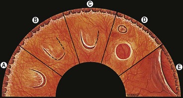
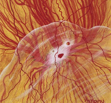
The ora serrata forms the junction between the retina and ciliary body and is characterized by the following (Fig 16.1):
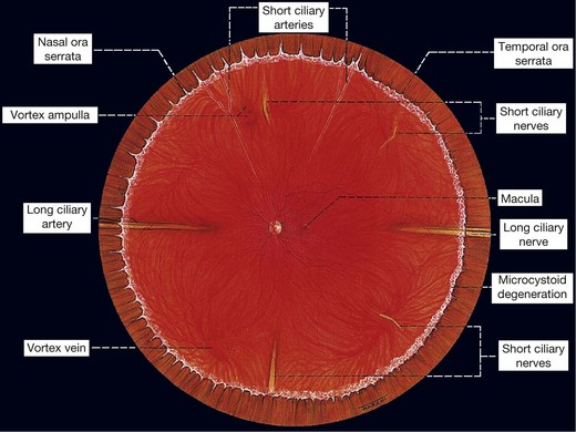
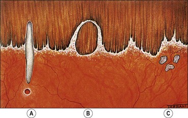
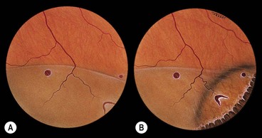
Fig. 16.2 Normal variants of the ora serrata. (A) Meridional fold with a small retinal hole at its base; (B) enclosed oral bay; (C) granular tissue
At the ora, fusion of the sensory retina with the retinal pigment epithelium (RPE) and choroid limits forward extension of subretinal fluid. However, there being no equivalent adhesion between the choroid and sclera, choroidal detachments may progress anteriorly to involve the ciliary body (ciliochoroidal detachment).
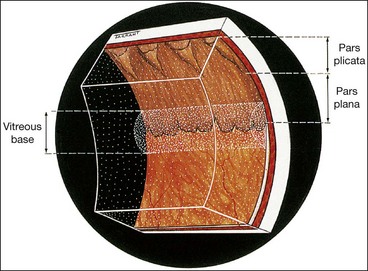
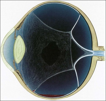
Vitreous base
The vitreous base is a 3–4 mm wide zone straddling the ora serrata (Fig. 16.3). An incision through the mid-part of the pars plana will usually be located anterior to the vitreous base. The cortical vitreous is strongly attached at the vitreous base, so that following acute posterior vitreous detachment (PVD), the posterior hyaloid face remains attached to the posterior border of the vitreous base. Pre-existing retinal holes within the vitreous base do not lead to RD. Severe blunt trauma may cause an avulsion of the vitreous base with tearing of the non-pigmented epithelium of the pars plana along its anterior border and of the retina along its posterior border.
Innocuous peripheral retinal degenerations
The peripheral retina extends from the equator to the ora serrata and may show the following innocuous lesions.
Definitions
Retinal detachment
A retinal detachment (RD) describes the separation of the neurosensory retina (NSR) from the retinal pigment epithelium (RPE). This results in the accumulation of subretinal fluid (SRF) in the potential space between the NSR and RPE. The main types of RD are:
Vitreous adhesions
Vitreoretinal traction
Vitreoretinal traction is a force exerted on the retina by structures originating in the vitreous, and may be dynamic or static. The difference between the two is crucial in understanding the pathogenesis of the various types of RD.
Posterior vitreous detachment
A posterior vitreous detachment (PVD) is a separation of the cortical vitreous from the internal limiting membrane (ILM) of the NSR posterior to the vitreous base. PVD can be classified according to the following characteristics:
Retinal break
A retinal break is a full-thickness defect in the sensory retina. Breaks can be classified according to (a) pathogenesis, (b) morphology and (c) location.
Clinical examination
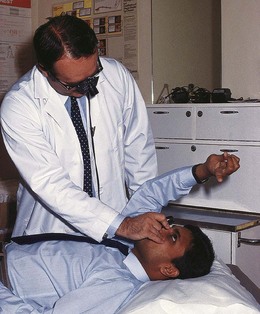
Head-mounted indirect ophthalmoscopy
Scleral indentation
Goldmann three-mirror examination
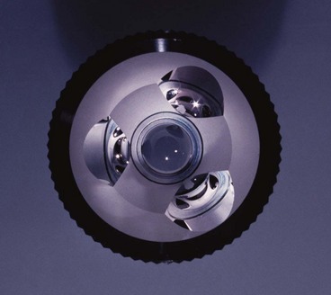
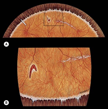
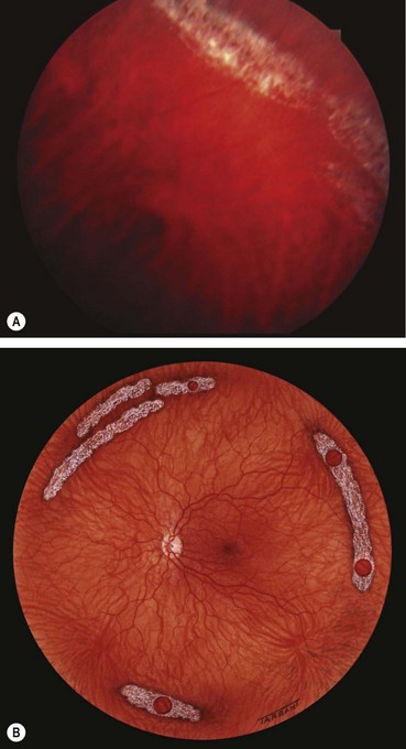
Fig. 16.12 (A) U-tear left of 12 o’clock and an island of lattice degeneration right of 12 o’clock; (B) the same lesions seen with the three-mirror lens positioned at 6 o’clock
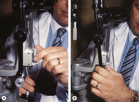
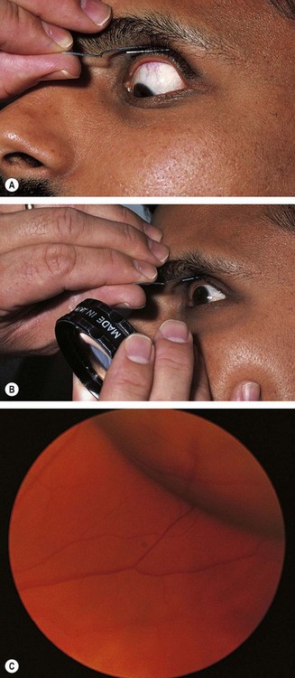
Fig. 16.13 Preparation of the slit-lamp for fundus examination. (A) Unlocking the screw; (B) tilting the illumination column
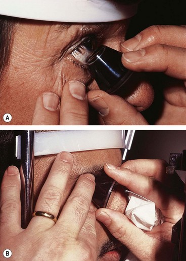
Fig. 16.14 (A) Insertion of the three-mirror lens into the lower fornix with the patient looking up; (B) three-mirror lens in position
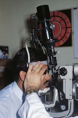
Fig. 16.15 The illumination column is tilted and positioned right of centre to view the oblique meridian at 1.30 and 7.30 o’clock
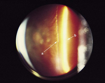
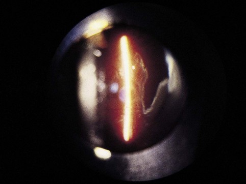
Fig. 16.16 Biomicroscopy showing posterior vitreous detachment without collapse. The posterior hyaloid face is indicated by the long arrow ‘a’ and the retina by the short arrow ‘b’
(Courtesy of CL Schepens, CL Trempe and M Takahashi, from Atlas of Vitreous Biomicroscopy, Butterworth-Heinemann, 1999)
Fundus drawing
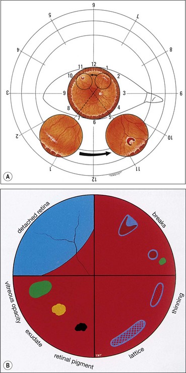
Finding the primary break
The primary break is the one responsible for the RD. A secondary break is not responsible for the RD because it was either present before the development of the RD or formeds after the retina detached. Finding the primary break is of paramount importance and aided by the following considerations.
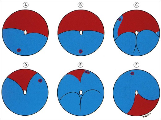
Fig. 16.18 Distribution of subretinal fluid in relation to the location of the primary retinal break (see text)
The above points are important because they aid in prevention of the treatment of a secondary break whilst overlooking the primary break. It is therefore essential to ensure that the shape of the RD corresponds to the location of a presumed primary retinal break.
Ultrasonography
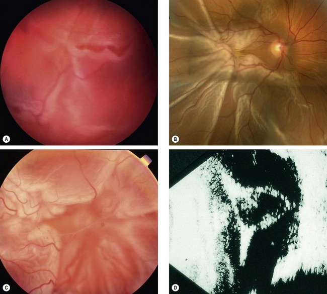
B-scan ultrasonography (US) is very useful in the diagnosis of RD in eyes with opaque media, particularly severe vitreous haemorrhage that precludes visualization of the fundus (see Figs 17.1C and D).
Principles
Technique
Each probe has a marker for orientation that correlates with a point on the display screen, usually the left.
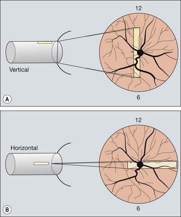
Fig. 16.19 Technique of ultrasound scanning of the globe. (A) Vertical scanning with the marker pointing towards the brow; (B) horizontal scanning with the marker pointing towards the nose
Gain adjusts the amplification of the echo signal, similar to volume control of a radio. Higher gain increases the sensitivity of the instrument in displaying weak echoes such as vitreous opacities. Lower gain only allows display of strong echoes such as the retina and sclera, though improves resolution because it narrows the beam.
Rhegmatogenous retinal detachment
Pathogenesis
Rhegmatogenous RD affects about 1 in 10 000 of the population each year and both eyes may eventually be involved in about 10% of patients. It is characterized by the presence of a retinal break held open by vitreoretinal traction that allows accumulation of liquefied vitreous under the NSR, separating it from the RPE. The retinal breaks responsible for RD are caused by interplay between dynamic vitreoretinal traction and an underlying weakness in the peripheral retina referred to as predisposing degeneration. Even though a retinal break is present, a RD will not occur if the vitreous is not at least partially liquefied and if the necessary traction is not present.
Dynamic vitreoretinal traction
Complications of acute PVD
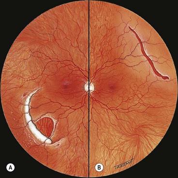
Following PVD, the sensory retina is no longer protected by the stable vitreous cortex, and can be directly affected by dynamic vitreoretinal tractional forces. The vision-threatening complications of acute PVD are dependent on the strength and extent of pre-existing vitreoretinal adhesions.
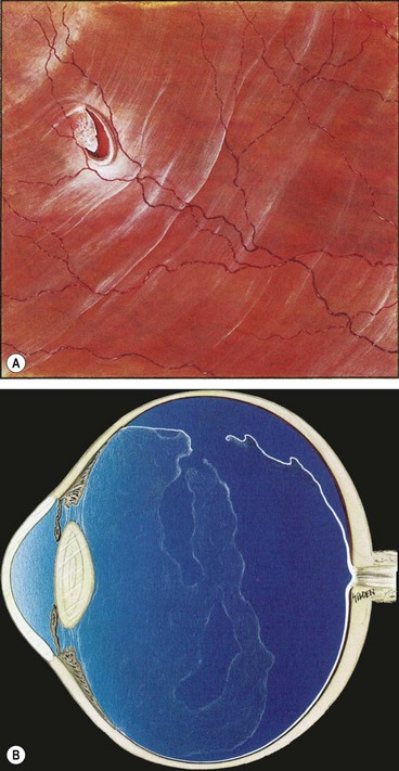
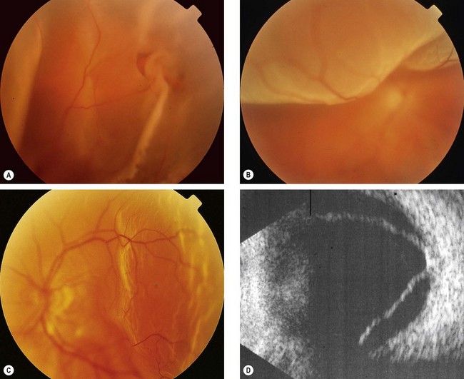
Fig. 16.22 (A) U-tear and localized subretinal fluid associated with acute posterior vitreous detachment; (B) the vitreous shows syneresis, posterior vitreous detachment with partial collapse, and retained attachment of cortical vitreous to the flap of the tear
(Courtesy of CL Schepens, ME Hartnett and T Hirose, from Schepens’ Retinal Detachment and Allied Diseases, Butterworth-Heinemann, 2000)
About 60% of all breaks develop in areas of the peripheral retina that show specific changes. These lesions may be associated with a spontaneous breakdown of pathologically thin retinal tissue to cause a retinal hole, or they may predispose to retinal tear formation in eyes with acute PVD. Retinal holes are round or oval, usually smaller than tears and carry a lower risk of RD. Retinal detachment without PVD is usually associated with either retinal dialysis, or round holes predominantly in young female myopes.
Lattice degeneration
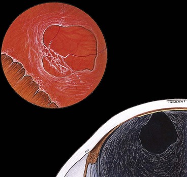
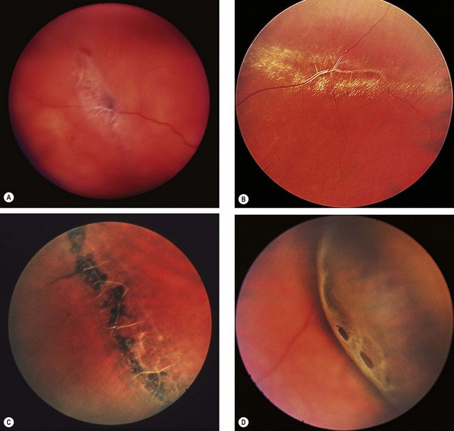
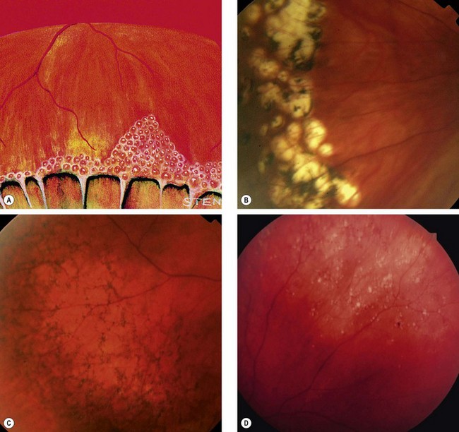
Fig. 16.24 Clinical features of lattice degeneration. (A) Small island of lattice with an arborizing network of white lines; (B) lattice associated with ‘snowflakes’; (C) lattice associated with RPE changes; (D) small holes within lattice seen on scleral indentation
(Courtesy of NE Byer, from The Peripheral Retina in Profile, A Stereoscopic Atlas, Criterion Press, Torrance, California, 1982 – figs B and D)
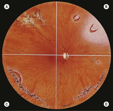
Fig. 16.25 Complications of lattice degeneration. (A) Atypical radial lattice without breaks; (B) two U-tears, the larger one of which shows a small patch of lattice on its flap and is surrounded by a small puddle of subretinal fluid; (C) linear tear along the posterior margin of lattice; (D) multiple small holes within islands of lattice
Snailtrack degeneration
Snailtrack degeneration is characterized by sharply demarcated bands of tightly packed ‘snowflakes’ which give the peripheral retina a white frost-like appearance. The islands are usually longer than in lattice degeneration and may be associated with overlying vitreous liquefaction. However, marked vitreous traction at the posterior border of the lesions is seldom present so that tractional U-tears rarely occur, although round holes within the snailtracks may be present (Fig. 16.26).
Degenerative retinoschisis
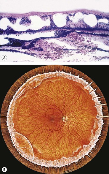
Fig. 16.27 Microcystoid degeneration. (A) Histology shows spaces in the nerve fibre layer delineated by delicate vertical columns of Müller cells; (B) circumferential microcystoid degeneration and mild retinoschisis in the inferotemporal and superotemporal quadrants
(Courtesy of J Harry and G Misson, from Clinical Ophthalmic Pathology, Butterworth-Heinemann, 2001)
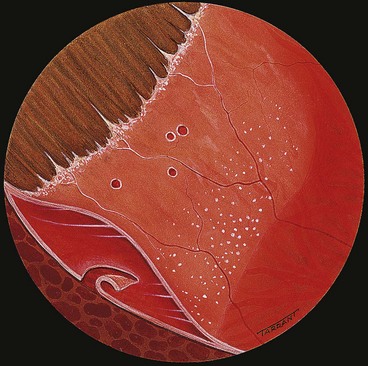
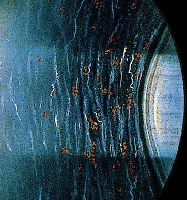
Fig. 16.28 Retinoschisis with breaks in both layers. The inner layer shows snowflakes and ‘silver-wiring’ of blood vessels, and the cavity is bridged by torn grey-white tissue
‘White with pressure’ and ‘white without pressure’
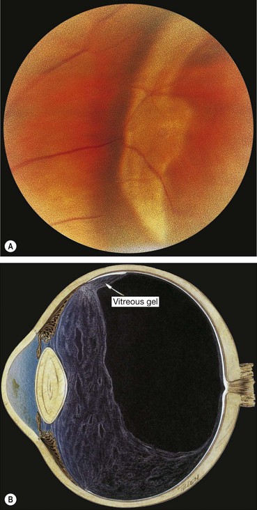
Fig. 16.31 (A) ‘White with pressure’; (B) extensive vitreous syneresis and strong attachment of condensed vitreous gel to an area of ‘white without pressure’
(Courtesy of NE Byer, from The Peripheral Retina in Profile, A Stereoscopic Atlas, Criterion Press, Torrance, California, 1982 – fig. A; CL Schepens, ME Hartnett and T Hirose, from Schepens’ Retinal Detachment and Allied Diseases, Butterworth-Heinemann, 2000 – fig. B)
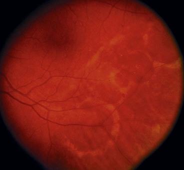
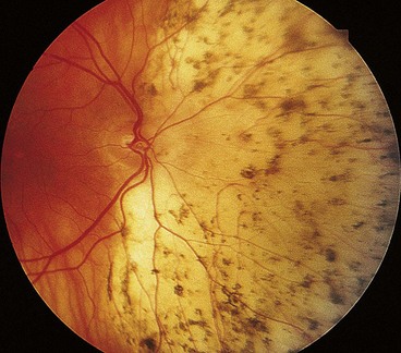
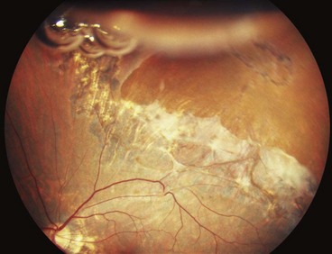
Diffuse chorioretinal atrophy
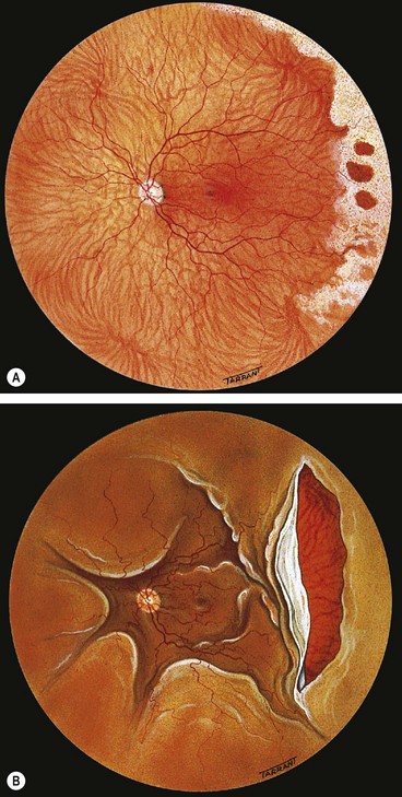
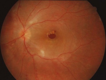
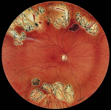
Diffuse chorioretinal atrophy is characterized by choroidal depigmentation and thinning of the overlying retina in the equatorial area of highly myopic eyes. Retinal holes developing in the atrophic retina may lead to RD (Fig. 16.33). Because of lack of contrast between the depigmented choroid and sensory retina, small holes may be very difficult to visualize without the help of slit-lamp biomicroscopy.
Significance of myopia
Although myopes make up 10% of the general population, over 40% of all RDs occur in myopic eyes; the higher the refractive error the greater is the risk of RD. The following interrelated factors predispose a myopic eye to RD:
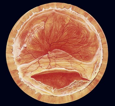
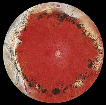
Fig. 16.34 Inferior retinal detachment in a highly myopic eye caused by a giant tear which developed along the posterior border of extensive lattice degeneration; also note lattice in the superotemporal quadrant
(Courtesy of CL Schepens, ME Hartnett and T Hirose, from Schepens’ Retinal Detachment and Allied Diseases, Butterworth-Heinemann, 2000)
Symptoms
The classic premonitory symptoms reported in about 60% of patients with spontaneous rhegmatogenous RD are flashing lights and vitreous floaters caused by acute PVD with collapse. After a variable period of time the patient notices a relative peripheral visual field defect which may progress to involve central vision.
Signs
General
Fresh retinal detachment
Long-standing retinal detachment
The following are the main features of a long-standing rhegmatogenous RD:
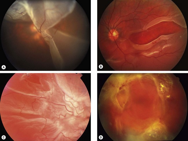
Proliferative vitreoretinopathy
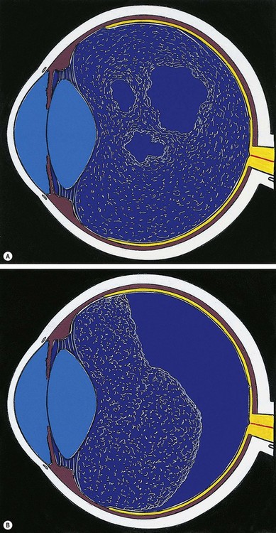
Proliferative vitreoretinopathy (PVR) is caused by epiretinal and subretinal membrane formation. Cell-mediated contraction of these membranes causes tangential retinal traction and fixed retinal folds (Fig. 16.40). Usually, PVR occurs following surgery for rhegmatogenous RD or penetrating injury. However, it may also occur in eyes with rhegmatogenous RD that have not had previous vitreoretinal surgery. The main features are retinal folds and rigidity so that retinal mobility induced by eye movements or scleral indentation is decreased. Classification is as follows although it should be emphasized that progression from one stage to the next is not inevitable.
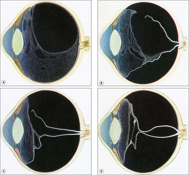
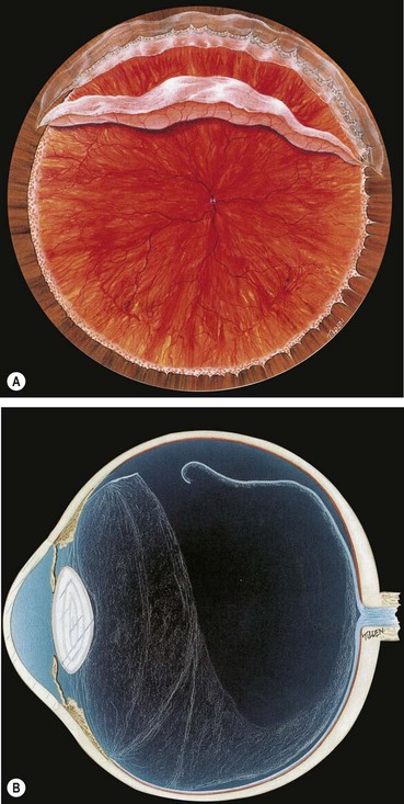
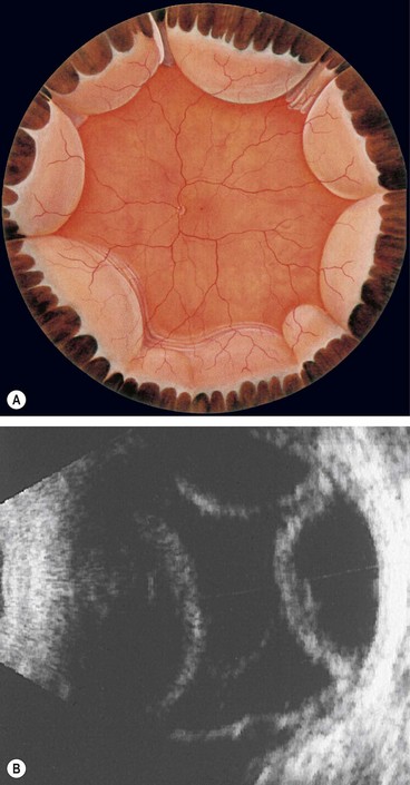
Fig. 16.40 Development of proliferative vitreoretinopathy (PVR). (A) Extensive vitreous syneresis; (B) total retinal detachment without PVR; shrunken vitreous is condensed and attached to the equator of the retina; (C) early PVR with anteriorly retracted vitreous gel and equatorial circumferential retinal folds; (D) advanced PVR with a funnel-like retinal detachment bridged by dense vitreous membranes
(Courtesy of CL Schepens, ME Hartnett and T Hirose, from Schepens’ Retinal Detachment and Allied Diseases, Butterworth-Heinemann, 2000)
Differential diagnosis
Apart from tractional and exudative RD, described below, the following conditions should be considered:
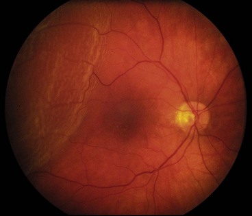
Degenerative retinoschisis
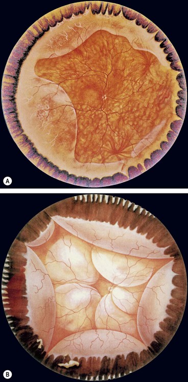
Fig. 16.42 (A) Degenerative retinoschisis showing peripheral vascular sheathing and ‘snowflakes’; (B) uveal effusion characterized by choroidal detachment and exudative retinal detachment
(Courtesy of CL Schepens, ME Hartnett and T Hirose, from Schepens’ Retinal Detachment and Allied Diseases, Butterworth-Heinemann, 2000 – figs A and B)
Uveal effusion syndrome
The uveal effusion syndrome is a rare, idiopathic condition which most frequently affects middle-aged hypermetropic men.
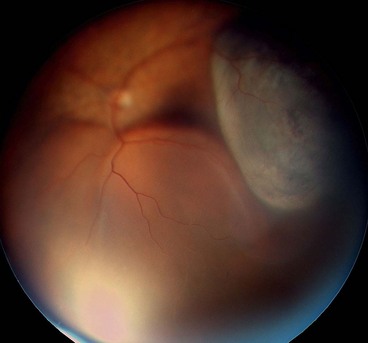
Choroidal detachment
Prophylaxis
Although, given the right circumstances, most retinal breaks can cause RD, some are more dangerous than others. Important criteria to be considered in the selection of patients for prophylactic treatment can be divided into: (a) characteristics of the break and (b) other considerations.
Characteristics of break
Other considerations
Clinical examples
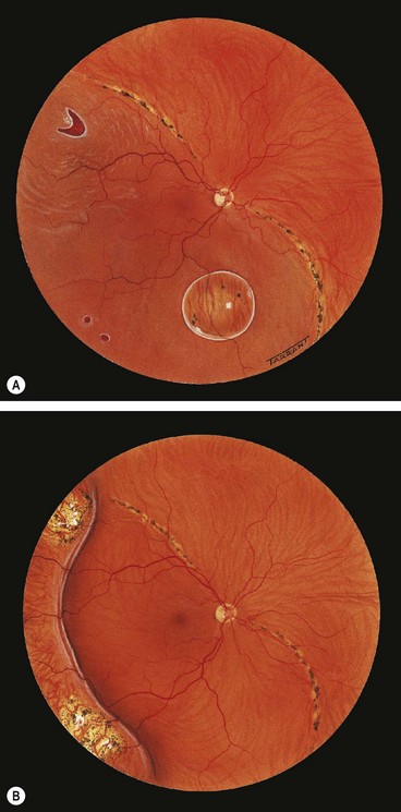
The following clinical examples illustrate the various risk factors just discussed (Fig. 16.44):
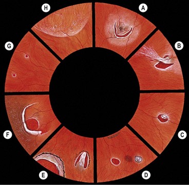
In the absence of associated retinal breaks neither lattice nor snailtrack degenerations require prophylactic treatment. However, prophylaxis should be considered if PVD has not yet occurred and the fellow eye has suffered a RD in the past.
Choice of treatment modalities
The three modalities used for prophylaxis are: (a) laser using a slit-lamp delivery system, (b) laser using an indirect ophthalmoscopic delivery system combined with scleral indentation and (c) cryotherapy. Large areas of cryotherapy may increase the risk of pigment epithelial cell release and subsequent epiretinal membrane formation; laser is the preferred modality for most lesions. Other considerations are as follows:
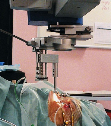
Technique of laser photocoagulation
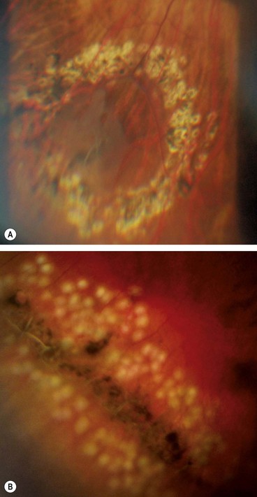
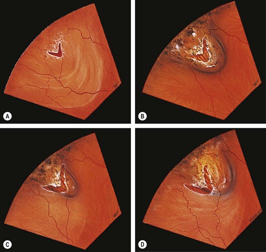
Fig. 16.45 (A) Appearance several weeks after prophylactic laser photocoagulation of a retinal tear; (B) appearance immediately after laser of lattice degeneration
(Courtesy of Dr Kaczmarek)
After treatment the patient should avoid strenuous physical exertion for about 7 days until an adequate adhesion has formed and the lesion is securely sealed; review should usually take place after 1–2 weeks.
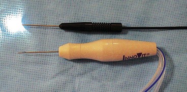
Technique of cryotherapy
After about 5 days pigmentation begins to appear. Initially the pigment is fine, then it becomes coarser and associated with a variable amount of chorioretinal atrophy (Fig. 16.46).
Causes of failure
Surgery
Indications for urgent surgery
It should be noted that the spread of SRF is governed by three factors:
It is therefore apparent that a patient with a fresh RD involving the superotemporal quadrant but with an intact macula (Fig. 16.48) should be operated on as soon as possible. In order to prevent SRF spreading to the macula, the patient should be positioned flat in bed with only one pillow and with the head turned so that the retinal break is in the most dependent position. For example, a patient with a right upper temporal RD should turn his head to the right. Preoperative bed rest is also desirable in eyes with bullous RDs because it may lessen the amount of SRF and facilitate surgery. Patients with dense fresh vitreous haemorrhage in whom visualization of the fundus is impossible should also be operated on as soon as possible if B-scan ultrasonography shows an underlying RD (see Fig. 17.1D).
Choice of technique
The aim of surgery is to successfully repair the detachment with minimal trauma and attendant risks. If the retinal break has accumulated too much SRF to be suitable for retinopexy then a surgical procedure will be required.
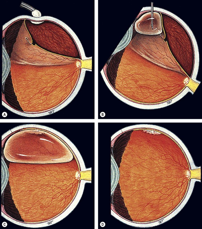
Pneumatic retinopexy
Pneumatic retinopexy is an outpatient procedure in which an intravitreal expanding gas bubble is used to seal a retinal break and reattach the retina without scleral buckling (Fig. 16.49). The most frequently used gases are sulphur hexafluoride (SF6) and the longer-acting perfluoropropane (C3F8). Pneumatic retinopexy has the advantage of being a relatively quick, minimally invasive, ‘office-based’ procedure. However, success rates are usually slightly less than those achievable with conventional scleral buckling surgery. The procedure is usually reserved for treatment of uncomplicated RD with a small retinal break or a cluster of breaks extending over an area of less than two clock hours situation in the upper two-thirds of the peripheral retina.
Principles of scleral buckling
Scleral buckling is a surgical procedure in which material sutured onto the sclera (explant) creates an inward indentation (buckle). Its purposes are to close retinal breaks by apposing the RPE to the sensory retina, and to reduce dynamic vitreoretinal traction at sites of local vitreoretinal adhesion.
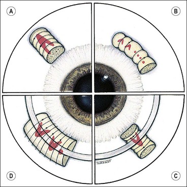
Technique of scleral buckling
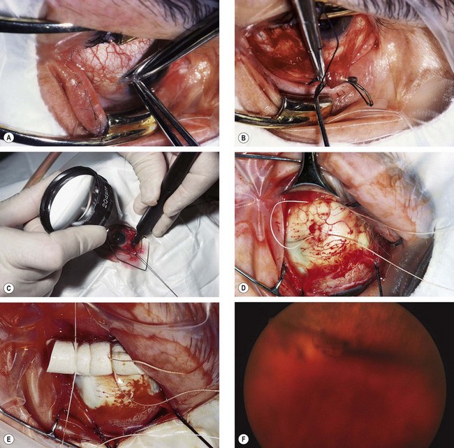
Fig. 16.51 Technique of scleral buckling. (A) Conjunctival incision; (B) insertion of bridle suture; (D) cryotherapy; mattress suture in place; (E) suture is tied over the sponge; (F) appearance of indentation – in this case the buckle is too anterior in relation to the tear and must be repositioned
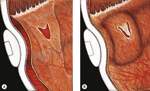
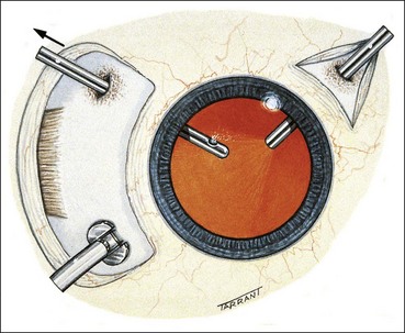
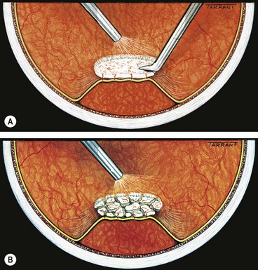
Drainage of subretinal fluid
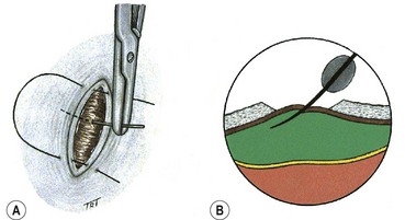
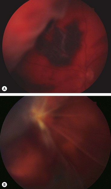
Fig. 16.54 Complications of subretinal fluid drainage. (A) Haemorrhage; (B) retinal incarceration into the drainage site
The following clinical examples will emphasize the most important aspects of management just discussed.
Fresh retinal detachment
Long-standing retinal detachment
Causes of failure
Tractional retinal detachment
The main causes of tractional RD are (a) proliferative retinopathy such as diabetic and retinopathy of prematurity, and (b) penetrating posterior segment trauma (see Ch. 21).
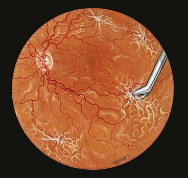
Pathogenesis of diabetic tractional retinal detachment
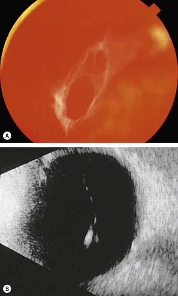
Diagnosis
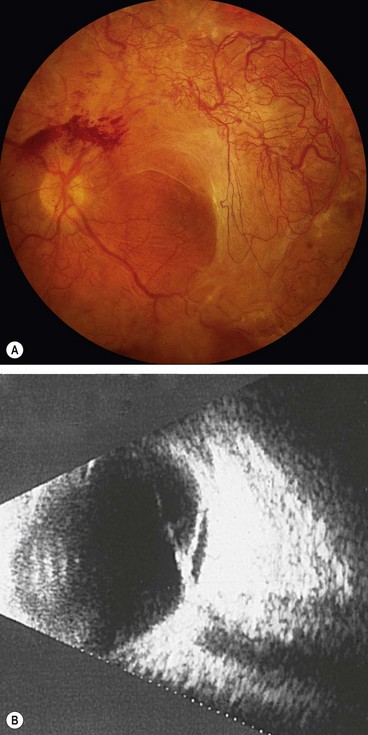
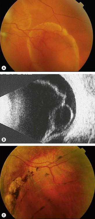
Fig. 16.58 (A) Tractional retinal detachment in severe proliferative diabetic retinopathy; (B) B-scan image of another patient shows posterior vitreous detachment and a shallow tractional retinal detachment
(Courtesy of P Saine – fig. A; RF Spaide, from Diseases of the Retina and Vitreous, WB Saunders, 1999 – fig. B)
Exudative retinal detachment
Pathogenesis
Exudative RD is characterized by the accumulation of SRF in the absence of retinal breaks or traction. It may occur in a variety of vascular, inflammatory and neoplastic diseases involving the NSR, RPE and choroid in which fluid leaks outside the vessels and accumulates under the retina. As long as the RPE is able to compensate by pumping the leaking fluid into the choroidal circulation, no fluid accumulates in the subretinal space and RD does not occur. However, when the normal RPE pump is overwhelmed, or if the RPE activity is decreased, then fluid starts to accumulate in the subretinal space. The main causes are the following:
Diagnosis
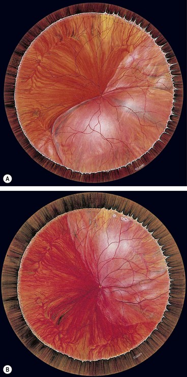
Fig. 16.59 Exudative retinal detachment with shifting fluid. (A) Inferior collection of subretinal fluid with the patient sitting; (B) the subretinal fluid shifts upwards when the patient assumes the supine position
(Courtesy of CL Schepens, E Hartnett and T Hirose, from Schepens’ Retinal Detachment and Allied Diseases, Butterworth-Heinemann, 2000)
Treatment
Treatment depends on the cause. Some cases resolve spontaneously, whilst others are treated with systemic corticosteroids (Harada disease and posterior scleritis). In some eyes with bullous central serous chorioretinopathy, the leak in the RPE can be sealed by argon laser photocoagulation.
Pars plana vitrectomy
Introduction
Instrumentation
The diameter of the shaft of most instruments is 0.9 mm (20-gauge); they are therefore interchangeable and can be inserted through either sclerotomy. Smaller 21g and 25g systems are becoming increasingly popular. These smaller sclerotomies do not usually require suturing but there is some concern that sealing occurs via vitreous incarceration with an increased risk of postoperative endophthalmitis.
Tamponading agents
Because the eye is usually left almost entirely gas-filled at the end of the procedure, most tamponading agents are used at an isovolumetric concentration (e.g. 20–30% for SF6 and 12–16% for C3F8).
Indications
Although most simple rhegmatogenous RD can be treated successfully by scleral buckling techniques, vitrectomy surgery has greatly improved the prognosis for more complex detachments. As techniques have improved and surgeons’ familiarity and confidence has grown, the threshold for vitrectomy surgery has fallen. Many surgeons now feel that morbidity and success rates are better with vitrectomy for all pseudophakic and aphakic RD, and for those that would otherwise require drainage of SRF. The guidelines below are therefore not absolute but intended to give some insight into the factors influencing the decision-making process.
Rhegmatogenous retinal detachment
Tractional retinal detachment
Technique
Basic vitrectomy
The above basic steps apply to all vitrectomies although transconjunctival small gauge systems do not require a peritomy or postoperative suturing. Subsequent steps depend on the characteristics of the RD as follows.
Closure of giant tears
Proliferative vitreoretinopathy
The aims of surgery in PVR are to release both transvitreal traction by vitrectomy and tangential (surface) traction by membrane dissection in order to restore retinal mobility and allow closure of retinal breaks.
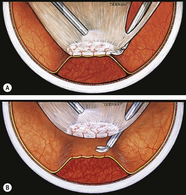
Tractional retinal detachment
The goal of vitrectomy in tractional RDs is to release anteroposterior and/or circumferential vitreoretinal traction. Because the membranes are vascularized, and the retina often friable, they cannot be simply peeled from the surface of the retina as this would result in haemorrhage and tearing of the retina. The two methods of removing fibrovascular membranes in diabetic tractional RDs are the following:
Postoperative complications
Raised intraocular pressure
Elevation of intraocular pressure may be caused by the following mechanisms:
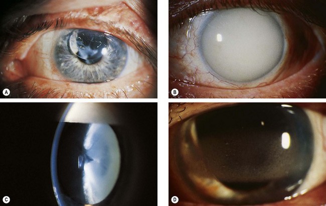
Fig. 16.70 Some complications of silicone oil injection. (A) Pupillary block glaucoma caused by oil in the anterior chamber; (B) late glaucoma due to trabecular blockage by emulsified oil; (C) cataract in an eye with emulsified oil (inverted ‘pseudo-hypopyon’); (D) band keratopathy
(Courtesy of Z Gregor – fig. D)
Cataract
Lens opacity may be caused by the following mechanisms:
Band keratopathy
Band keratopathy may occur as a result of prolonged contact between silicone oil and the corneal endothelium (Fig. 16.70D).