CHAPTER 11 Surveying
When a fixed partial denture (FPD) is prepared, the orientation of the diamond bur is controlled to remove an amount of tooth structure necessary to satisfy the requirements of the path of insertion for the prosthesis. Accomplishment of parallel preparations is ultimately verified by complete seating of the prosthesis, but could be verified on the master cast or dies by the use of the surveyor. Once the FPD is fabricated and completely seated, it is ensured full engagement of the entire circumference of and occlusal support from the abutment retainers. If adequate resistance form and fit of the prosthesis are provided, the chance for functional stability equivalent to natural teeth is good. This could not be ensured unless the relationship of the fixed prosthesis and the prepared teeth were carefully controlled.
For a removable prosthesis, the necessity for appropriately planned and executed tooth preparation, followed by verification of a well-fitting prosthesis that engages the teeth as planned, is equally important. As was briefly mentioned in Chapter 7, a dental surveyor is vitally important to the planning, execution, and verification of appropriate mouth modifications for a removable partial denture. Although it does not necessarily affect the occlusal rest preparations on abutment teeth, use of the surveyor is critical for planning the modifications of all tooth surfaces that will be involved in support, stabilization, and retention of the prosthesis. In this role, the use of a surveyor to determine the needed mouth preparation is vitally important in helping to provide stable and comfortable removable prostheses.
A dental surveyor has been defined as an instrument used to determine the relative parallelism of two or more surfaces of the teeth or other parts of the cast of a dental arch. Therefore the primary purpose of surveying is to identify the modifications of oral structures that are necessary to fabricate a removable partial denture that will have a successful prognosis. It is the modification of tooth surfaces to accommodate placement of the component parts of the partial denture in their designated ideal positions on abutment teeth that facilitates this prognosis.
Any one of several moderately priced surveyors on the market will adequately accomplish the procedures necessary to design and construct a partial denture. In addition, these surveyors may be used to parallel internal rests and intracoronal retainers. With a handpiece holder added, they may be used to machine internal rests and to make the guiding-plane surfaces of abutment restorations parallel.
Description of Dental Surveyor
The most widely used surveyors are the Ney (Figure 11-1) and the Jelenko (Figure 11-2). Both of these are precision-made instruments. They differ principally in that the Jelenko arm swivels, whereas the Ney arm is fixed. The technique for surveying and trimming blockout is therefore somewhat different. Other surveyors also differ in this respect, and the dentist may prefer one over another for this reason.
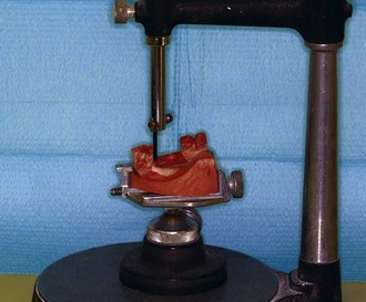
Figure 11-1 The Ney surveyor is widely used because of its simplicity and durability. Dental students should be required to own such a surveyor. By becoming familiar with and dependent on its use, they are more likely to continue using the surveyor in practice as a necessary piece of equipment toward more adequate diagnosis, effective treatment planning, and performance of many other aspects of prosthodontic treatment.
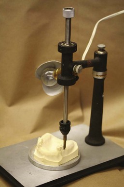
Figure 11-2 The Jelenko surveyor. Note the spring-mounted paralleling tool and swivel at the top of the vertical arm. The horizontal arm may be fixed in any position by tightening the nut at the top of the vertical arm.
The principal parts of the Ney surveyor are as follows:
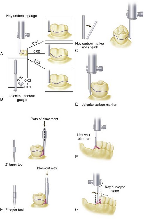
Figure 11-3 Various tools that may be used with a dental surveyor. A, Ney undercut gauges. B, Jelenko undercut gauge. C, Ney carbon marker with metal reinforcement sheath. D, Jelenko carbon marker. E, Tapered tools, 2- and 6-degree, for trimming blockout when some nonparallelism is desired. F, Ney wax trimmer for paralleling blockout. G, Surveying blade used for trimming blockout.
The principal parts of the Jelenko surveyor are essentially the same as those of the Ney surveyor except that when the nut at the top of the vertical arm is loosened, the horizontal arm may be made to swivel. The objective of this feature, originally designed by Dr. Noble Wills, is to permit freedom of movement of the arm in a horizontal plane rather than to depend entirely on the horizontal movement of the cast. To some this is confusing because two horizontal movements must thus be coordinated. For those who prefer to move the cast only in horizontal relationship to a fixed vertical arm, the nut may be tightened and the horizontal arm used in a fixed position.
Another difference between Ney and Jelenko surveyors is that the vertical arm on the Ney surveyor is retained by friction within a fixed bearing. The shaft may be moved up or down within this bearing but remains in a vertical position until again moved. The shaft may be fixed in any vertical position desired by tightening a setscrew. In contrast, the vertical arm of the Jelenko surveyor is spring mounted and returns to the top position when it is released. It must be held down against spring tension while it is in use, which to some is a disadvantage. The spring may be removed, but the friction of the two bearings supporting the arm does not hold it in position as securely as does a bearing designed for that purpose. These minor differences in the two surveyors lead to personal preference but do not detract from the effectiveness of either surveyor when each is properly used.
Because the shaft on the Ney surveyor is stable in any vertical position—yet may be moved vertically with ease—it lends itself well for use as a drill press when a handpiece holder is added (Figure 11-4). The handpiece may thus be used to cut recesses in cast restorations with precision with burs or carborundum points of various sizes in a dental handpiece.
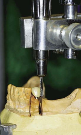
Figure 11-4 Lab handpiece clamp. Handpiece holders attach to the vertical spindle of surveyors and may be used to create and refine any parallel surface on a surveyed crown, as a drill press to prepare internal rests and recesses in patterns and/or castings, and to establish lingual surfaces above the ledge that are parallel to the path of placement in abutment restorations.
Several other types of surveyors have been designed and are in use today. Many of these are elaborate and costly, yet provide little advantage over simpler types of surveyors.
Purposes of the Surveyor
The surveyor may be used for surveying the diagnostic cast, recontouring abutment teeth on the diagnostic cast, contouring wax patterns, measuring a specific depth of undercut, surveying ceramic veneer crowns, placing intracoronal retainers, placing internal rests, machining cast restorations, and surveying and blocking out the master cast.
Surveying the Diagnostic Cast
Surveying the diagnostic cast is essential to effective diagnosis and treatment planning. The objectives are as follows:
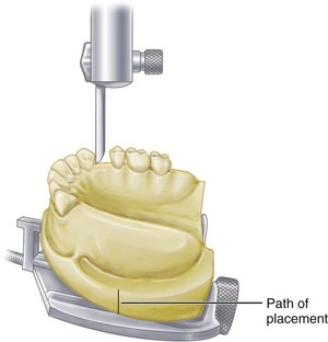
Figure 11-5 Tilt of the cast on the adjustable table of a surveyor in relation to the vertical arm establishes the path of placement and removal that the removable partial denture will take. All mouth preparations must be made to conform to this determined path of placement, which has been recorded by scoring the base of the cast or by tripoding.
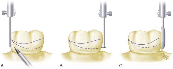
Figure 11-6 A, Solid line represents the height of contour on the abutment at selected orientation of the diagnostic cast to the vertical spindle of the surveyor. Dotted line represents the desirable height of the contour for optimally locating components of the direct retainer assembly. A 0.01-inch (0.25-mm) undercut gauge is used to mark the location of the tip of the retentive arm of the direct retainer. B, By reducing the axial contour of the tooth by only 0.01 inch, the optimum height of contour can be achieved without exposing the dentin. C, Stone tooth is trimmed with a surveyor blade to the desired height of contour. The trimmed area is marked in red pencil and serves as a blueprint for similar recontouring in the mouth. If one can safely assume that the enamel is 1 to 1.5 mm thick in the area of contemplated reduction, only 0.25 mm of enamel needs to be removed to achieve the optimum height of contour.
Contouring Wax Patterns
The surveyor blade is used as a wax carver during this phase of mouth preparation, so that the proposed path of placement may be maintained throughout the preparation of cast restorations for abutment teeth (Figure 11-7).
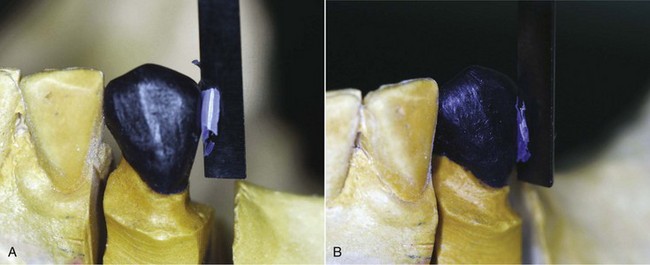
Figure 11-7 After the cast has been oriented to the surveyor at the predetermined path of placement, designated axial surfaces of the wax pattern are altered with the surveyor blade to meet specific requirements for placement of framework components. A, Wax pattern is carved with the surveyor blade to produce a distal guide-plane surface parallel to the selected path of insertion. B, Same pattern is modified from the distal guide plane along the buccal surface to align the surface with the height of contour most favorable to the direct retainer specifications.
Guiding planes on all proximal surfaces of wax patterns adjacent to edentulous areas should be made parallel to the previously determined path of placement. Similarly, all other tooth contours that will be contacted by rigid components should be made parallel. The surfaces of restorations on which reciprocal and stabilizing components will be placed should be contoured to permit their location well below occlusal surfaces and on nonretentive areas. Those surfaces of restorations that are to provide retention for clasp arms should be contoured so that retentive clasps may be placed in the cervical third of the crown and to the best esthetic advantage. Generally, a small amount of undercut from 0.01 to 0.02 inch (0.250 to 0.50 mm) or less is sufficient for retentive purposes.
Surveying Ceramic Veneer Crowns
Ceramic veneer crowns are often used to restore abutment teeth on which extracoronal direct retainers will be placed. The surveyor is used to contour all areas of the wax pattern for the veneer crown except the buccal or labial surface. It must be remembered that one of the principal goals in using a porcelain veneer restoration is to develop an esthetic replica of a natural tooth. It is unlikely that the ceramic veneer portion can be fabricated exactly to the form required for the planned placement of retentive clasp arms without some reshaping with stones. Before the final glaze is accomplished, the abutment crowns should be returned to the surveyor on a full arch cast to ensure the correct contour of the veneered portions or to locate those areas that need recontouring (Figure 11-8). The final glaze is accomplished only after the crowns have been recontoured.
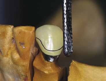
Figure 11-8 Resultant metal-ceramic surveyed crown from Figure 11-7, which is being refined to maintain the distal guide plane and buccal height of the contour previously designed. Final glaze has not been placed on the veneer crown and required alterations of surfaces to conform to ideal placement of the retainer (solid line) can be performed by machining. Final glaze is produced only after necessary recontouring is accomplished.
Placement of Intracoronal Retainers (Internal Attachments)
In the placement of intracoronal retainers, the surveyor is used as follows:
The student is referred to the “Selected Reading Resources” section of the textbook for sources of information on intracoronal retainers (internal attachments).
Placement of Internal Rest Seats
The surveyor may be used as a drill press, with a dental handpiece attached to the vertical arm by a handpiece holder. Internal rest seats may be carved in the wax patterns and further refined with the handpiece after casting, or the entire rest seat may be cut in the cast restoration with the handpiece. It is best to carve the outline form of the rest seat in wax and merely refine the casting with the handpiece.
An internal rest differs from an internal attachment in that some portion of the prosthesis framework is waxed and cast to fit into the rest seat rather than a matched key and keyway attachment used (see Figures 6-13 and 6-14). The former is usually nonretentive but provides a definite seat for a removable partial denture or a cantilever rest for a broken-stress fixed partial denture. When they are used with fixed partial dentures, nonparallel abutment pieces may be placed separately.
The internal rest in partial denture construction provides a positive occlusal support that is more favorably located in relation to the rotational axis of the abutment tooth than the conventional spoon-shaped occlusal rest. It also provides horizontal stabilization through the parallelism of the vertical walls, thereby serving the same purpose as stabilizing and reciprocal arms placed extracoronally. Because of the movement of a distal extension base, more torque may be applied to the abutment tooth by an interlocking type of rest, and for this reason its use in conjunction with a distal extension partial denture is considered to be contraindicated. The ball-and-socket, spoon-shaped occlusal, or noninterlocking, rest should be used in distal extension partial denture designs. Use of the dovetailed or interlocking internal rest should be limited to tooth-supported removable restorations, except when it is used in conjunction with some kind of stress-breaker between the abutments and the movable base. The use of stress-breakers has been discussed in Chapter 9.
Internal rest seats may be made in the form of a nonretentive box, a retentive box fashioned after the internal attachment, or a semiretentive box. In the latter, the walls are usually parallel and nonretentive, but a recess in the floor of the box prevents proximal movement of the male portion. Internal rest seats are cut with dental burs of various sizes and shapes. Tapered or cylindrical fissure burs are used to form the vertical walls, and small round burs are used to cut recesses in the floor of the rest seat.
Machining Cast Restorations
With a handpiece holder attached (see Figure 11-4), the axial surfaces of cast and ceramic restorations may be refined by machining with a suitable cylindrical carborundum point. Proximal surfaces of crowns and inlays, which will serve as guiding planes, and vertical surfaces above crown ledges may be improved by machining, but only if the relationship of one crown to another is correct (see Figure 14-9). Unless the seating of removable dies is accurate and they are held in place with additional stone or plaster, cast restorations should first be tried in the mouth and then transferred, by means of a plaster or acrylic-resin index impression, to a reinforced stone cast for machining purposes. The new cast is then positioned on the surveyor, conforming to the path of placement of the partial denture, and vertical surfaces are machined with a true-running cylindrical carborundum point.
Although machined parallelism may be considered ideal and beyond the realm of everyday application, its merits more than justify the additional steps required to accomplish it. When such parallelism is accomplished and reproduced in a master cast, it is essential that subsequent laboratory steps be directed toward the use of these parallel guiding plane surfaces.
Surveying the Master Cast
Because surveying the master cast follows mouth preparations, the path of placement, the location of retentive areas, and the location of remaining interference must be known before the final design of the denture framework is completed. The objectives of surveying the master cast are as follows:
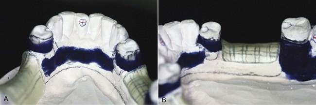
Figure 11-9 Master casts are modified by the addition of wax relief to nonbearing regions and by placement of blockout wax parallel to the path of insertion at regions beneath the height of contour where framework contact is not planned (i.e., all areas except retentive clasp tips). A, Blockout wax is provided for tooth contours beneath the height of contour on teeth #21 and #28. B, Similar blockout was accomplished for mandibular molar #31. Blockout is carved with a straight surveyor blade to ensure parallelism with the identified path of insertion.
The partial denture must be designed so that (1) it will not stress abutment teeth beyond their physiologic tolerance; (2) it can be easily placed and removed by the patient; (3) it will be retained against reasonable dislodging forces; and (4) it will not create an unfavorable appearance. It is necessary that the diagnostic cast be surveyed with these principles in mind. Mouth preparation should therefore be planned in accordance with certain factors that will influence the path of placement and removal.
Factors that Determine Path of Placement and Removal
The factors that will determine the path of placement and removal are guiding planes, retentive areas, interference, and esthetics.
Guiding Planes
Proximal tooth surfaces that bear a parallel relationship to one another must be found or must be created to act as guiding planes during placement and removal of the prosthesis. Guiding planes are necessary to ensure the passage of rigid parts of the prosthesis past existing areas of interference. Thus the denture can be easily placed and removed by the patient without strain on the teeth contacted or on the denture itself and without damage to the underlying soft tissues.
Guiding planes are also necessary to ensure predictable clasp assembly function, including retention and stabilization. For a clasp to be retentive, its retentive arm must be forced to flex. Hence, guiding planes are necessary to give a positive direction to the movement of the restoration to and from its terminal position.
Retentive Areas
Retentive areas must exist for a given path of placement and must be contacted by retentive clasp arms that are forced to flex over a convex surface during placement and removal. Satisfactory clasp retention is no more than the resistance of metal to deformation. For a clasp to be retentive, its path of escapement must be other than parallel to the path of removal of the denture itself; otherwise it would not be forced to flex and thereby generate the resistance known as retention. Clasp retention therefore depends on the existence of a definite path of placement and removal.
Although desirable, retention at each principal abutment may not be balanced in relation to the tooth on the opposite side of the arch (exactly equal and opposite in magnitude and relative location); however, positive cross-arch reciprocation to retentive elements must be present. Retention should be sufficient only to resist reasonable dislodging forces. In other words, it should be the minimum acceptable for adequate retention against reasonable dislodging forces.
Fairly even retention may be obtained by one of two means. One is to change the path of placement to increase or decrease the angle of cervical convergence of opposing retentive surfaces of abutment teeth. The other is to alter the flexibility of the clasp arm by changing its design, its size and length, or the material of which it is made.
Interference
The prosthesis must be designed so that it may be placed and removed without encountering tooth or soft tissue interference. A path of placement may be selected that encounters interference only if the interference can be eliminated during mouth preparations or on the master cast by a reasonable amount of blockout. Interference may be eliminated during mouth preparations by surgery, extraction, modification of interfering tooth surfaces, or alteration of tooth contours with restorations.
Generally, interference that cannot be eliminated for one reason or another will take precedence over the factors of retention and guiding planes. Sometimes certain areas can be made noninterfering only by selecting a different path of placement at the expense of existing retentive areas and guiding planes. These must then be modified with restorations that are in harmony with the path dictated by the existing interference. On the other hand, if areas of interference can be eliminated by various reasonable means, this should be done. When this occurs, the axial contours of existing abutments may frequently be used with little alteration.
Esthetics
By one path of placement, the most esthetic location of artificial teeth is made possible, and less clasp metal and base material may be displayed.
The location of retentive areas may influence the path of placement selected; therefore retentive areas should always be selected with the most esthetic locations of clasps in mind. When restorations are to be made for other reasons, they should be contoured to permit the least display of clasp metal. Generally, less metal will be displayed if the retentive clasp is placed at a more distogingival area of tooth surface, made possible by the path of placement selected or by the contour of the restorations.
Esthetics also may dictate the choice of path selected when missing anterior teeth must be replaced with the partial denture. In such situations, a more vertical path of placement is often necessary so that neither the artificial teeth nor the adjacent natural teeth will have to be modified excessively (Figure 11-10). In this instance, esthetics may take precedence over other factors. This necessitates the preparation of abutment teeth to eliminate interferences and to provide guiding planes and retention in harmony with that path of placement dictated by esthetic factors.
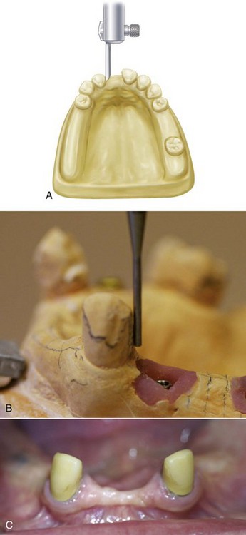
Figure 11-10 A, When anterior teeth must be replaced with the removable partial denture, the selected vertical path should consider the junction of the natural tooth and the denture tooth. The path of insertion that requires the least amount of alteration of the natural teeth and the denture tooth (maximizing natural embrasure contours) is desirable. B, Distal of canine slightly altered to accommodate the path that optimizes anterior denture tooth placement. C, Canine crowns required to satisfy desired contours of the natural tooth and the denture teeth.
Because the primary consideration should be the preservation of remaining oral tissues, esthetics should not be allowed to jeopardize the success of the partial denture. The replacement of missing anterior teeth therefore should be accomplished by means of fixed partial dentures whenever possible, especially if the mechanical and functional effectiveness of the partial denture will require significant tooth preparation.
Step-By-Step Procedures in Surveying A Diagnostic Cast
Attach the cast to the adjustable surveyor table by means of the clamp provided. Position the adjustable table so that the occlusal surfaces of the teeth are approximately parallel to the platform (Figure 11-11). Such an orientation is a tentative but practical way to start considering the factors that influence the path of placement and removal.
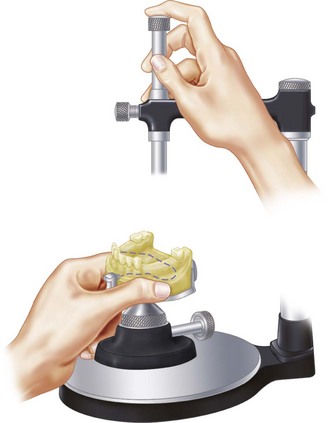
Figure 11-11 Recommended method for manipulating the dental surveyor. The right hand is braced on the horizontal arm of the surveyor, and the fingers are used, as illustrated, to raise and lower the vertical shaft in its spindle. The left hand holding the cast on the adjustable table slides horizontally on the platform in relation to the vertical arm. The right hand must be used to loosen and tighten the tilting mechanism as a suitable anteroposterior and lateral tilt of the cast in relation to the surveyor is being determined.
Guiding Planes
Determine the relative parallelism of proximal surfaces of all of the potential abutment teeth by contacting the proximal tooth surfaces with the surveyor blade or diagnostic stylus. Alter the cast position anteroposteriorly until these proximal surfaces are in as close to a parallel relation to one another as possible, or near enough that they can be made parallel by recontouring. For posterior modification spaces, this will determine the anteroposterior tilt of the cast in relation to the vertical arm of the surveyor (Figure 11-12). Although the surveyor table is universally adjustable, it should be thought of as having only two axes, thus allowing only anteroposterior and lateral tilting.
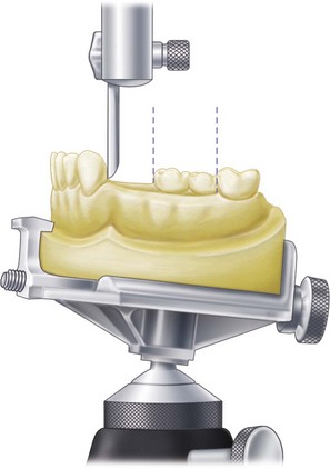
Figure 11-12 Relative parallelism of proximal tooth surfaces will determine anteroposterior tilt of the cast in relation to the vertical arm of the surveyor.
When a choice is made between having contact with a proximal surface at the cervical area only or contact at the marginal ridge only, the latter is preferred because a plane may then be established by recontouring (Figure 11-13). It is obvious that when only gingival contact exists, a restoration is the only means of establishing a guiding plane. Therefore, if a tilt that does not provide proximal contact is apparent, the proximal surface must be established with some kind of restoration.
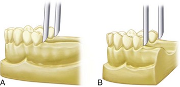
Figure 11-13 When the most desirable anteroposterior tilt of the cast in relation to the surveyor blade is determined, a choice must be made between positions illustrated in A and B. In A, the distal surface of the left premolar abutment would have to be extended by means of a restoration. In B, the right premolar could be altered slightly to provide an acceptably parallel guiding plane. Unless restorations are necessary for other reasons, the tilt shown in B is preferred.
The end result of selecting a suitable anteroposterior tilt should be to provide the greatest combined areas of parallel proximal surfaces that may act as guiding planes. Other axial surfaces of abutment teeth may also be used as guiding planes. This is realized most often by having the stabilizing component of the direct retainer assembly contacting in its entirety the axial surface of the abutment, which has been found or made parallel to the path of placement (see Figure 14-7Figure 14-8Figure 14-9). Therefore a lateral tilt of the cast to the vertical arm of the surveyor must also be considered, as well as the anteroposterior tilt, when guiding planes are used.
Retentive Areas
Through contact of buccal and lingual surfaces of abutment teeth with the surveyor blade, the amount of retention existing below their height of convexity may be determined. This is best accomplished by directing a small source of light toward the cast from the side away from the dentist. The angle of cervical convergence is best observed as a triangle of light between the surveyor blade and the apical portion of the tooth surface being studied (see Figure 7-41).
Alter the cast position by tilting it laterally until similar retentive areas exist on the principal abutment teeth. If only two abutment teeth are involved, as in a Kennedy Class I partially edentulous arch, they are both principal abutments. However, if four abutment teeth are involved (as they are in a Kennedy Class III, modification 1 arch), they are all principal abutments, and retentive areas should be located on all four. But if three abutment teeth are involved (as they are in a Kennedy Class II, modification 1 arch), the posterior abutment on the tooth-supported side and the abutment on the distal extension side are considered to be the principal abutments, and retention needs to be equalized accordingly. The third abutment may be considered to be secondary, and less retention is expected from it than from the other two. An exception is when the posterior abutment on the tooth-supported side has a poor prognosis and the denture is designed to ultimately be a Class I. In such a situation, the two stronger abutments are considered to be principal abutments.
When the cast is tilted laterally to establish reasonable uniformity of retention, it is necessary that the table be rotated about an imaginary longitudinal axis without disturbing the anteroposterior tilt previously established. The resulting position is one that provides or makes possible parallel guiding planes and provides for acceptable retention on the abutment teeth. It should be noted that this most desirable position will always require some tooth modification to be achieved. Note that possible interference to this tentative path of placement has not, as yet, been taken into consideration.
Interference
If a mandibular cast is being surveyed, check the lingual surfaces that will be crossed by a lingual bar major connector during placement and removal. Bony prominences and lingually inclined premolar teeth are the most common causes of interference to a lingual bar connector.
If the interference is bilateral, surgery or recontouring of lingual tooth surfaces, or both, may be unavoidable. If the interference is only unilateral, a change in the lateral tilt may avoid an area of tooth or tissue interference. In changing the path of placement to prevent interference, previously established guiding planes and an ideal location for retentive elements may be lost. Then the decision must be made whether to remove the existing interference by whatever means necessary or to resort to restorations on the abutment teeth, thereby changing the proximal and retentive areas to conform to the new path of placement.
In a like manner, bony undercuts that will offer interference to the seating of denture bases must be evaluated and the decision made to remove them surgically; to change the path of placement at the expense of modifying or restoring teeth to achieve guiding planes and retention; or to design denture bases to avoid such undercut areas. The latter may be done by shortening buccal and labial flanges and distolingual extension of the denture bases. However, it should be remembered that the maximum area available for support of the denture base should be used whenever possible.
Interference to major connectors rarely exists in the maxillary arch. Areas of interference are usually found on buccally inclined posterior teeth and those bony areas on the buccal aspect of edentulous spaces. As with the mandibular cast, the decision must be made whether to eliminate them, to change the path of placement at the expense of modifying or restoring teeth to achieve the required guiding planes and retention, or to design the connectors and bases to avoid them.
Other areas of possible interference to be evaluated are those surfaces of abutment teeth that will support or be crossed by minor connectors and clasp arms. Although interference to vertical minor connectors may be blocked out, doing so may cause discomfort to the patient’s tongue and may create objectionable spaces, which could result in the trapping of food. Also it is desirable that tooth surfaces contacted by vertical connectors be used as auxiliary guiding planes whenever possible. Too much relief is perhaps better than too little because of the possibility of irritation to soft tissues. It is always better that the relief be placed with some objective in mind. If possible, a minor connector should pass vertically along a tooth surface that is parallel to the path of placement (which is considered ideal) or tapered occlusally. If tooth undercuts that necessitate the use of an objectionable amount of blockout exist, they may be eliminated or minimized by slight changes in the path of placement and/or eliminated during mouth preparations. The need for such alteration should be indicated on the diagnostic cast in red pencil after final acceptance of a path of placement.
Tooth surfaces on which reciprocal and stabilizing clasp arms will be placed should be studied to see whether sufficient areas exist above the height of convexity for the placement of these components. The addition of a clasp arm to the occlusal third of an abutment tooth adds to its occlusal dimension and therefore to the occlusal loading of that tooth. Nonretentive and stabilizing clasp arms are best located between the middle third and the gingival third of the crown rather than on the occlusal third.
Areas of interference to proper placement of clasp arms can be eliminated by reshaping tooth surfaces during mouth preparations. These areas should be indicated on the diagnostic cast. Areas of interference to the placement of clasps may necessitate minor changes in the path of placement or changes in the clasp design. For example, a bar clasp arm originating mesially from the major connector to provide reciprocation and stabilization might be substituted for a distally originating circumferential arm.
Areas of interference often overlooked are the distal line angles of premolar abutment teeth and the mesial line angles of molar abutments. These areas frequently offer interference to the origin of circumferential clasp arms. If not detected at the time of initial survey, they are not included in the plan for mouth preparations. When such an undercut exists, the following three alternatives may be considered:
When the retentive area is located objectionably high on the abutment tooth or the undercut is too severe, interference may also exist on tooth surfaces that support retentive clasps. Such areas of extreme or high convexity must be considered as areas of interference and should be reduced accordingly. These areas are likewise indicated on the diagnostic cast for reduction during mouth preparations.
Esthetics
The path of placement thus established must still be considered from the standpoint of esthetics, as to both the location of clasps and the arrangement of artificial teeth.
Clasp designs that will provide satisfactory esthetics for any given path of placement usually may be selected. In some instances, gingivally placed bar clasp arms may be used to advantage; in others, circumferential clasp arms located cervically may be used. This is especially true when other abutment teeth located more posteriorly may bear the major responsibility for retention. In still other instances, a tapered wrought-wire retentive clasp arm may be placed to better esthetic advantage than a cast clasp arm. The placement of clasp arms for esthetic reasons does not ordinarily justify altering the path of placement at the expense of mechanical factors. However, it should be considered concurrently with other factors, and if a choice between two paths of insertion of equal merit permits a more esthetic placement of clasp arms by one path than the other, that path should be given preference.
When anterior replacements are involved, the choice of path is limited to a more vertical one for reasons previously stated. In this instance alone, esthetics must be given primary consideration, even at the expense of altering the path of placement and making all other factors conform. This factor should be remembered when the other three factors are considered, so that compromises can be made at the time other factors are being considered.
Final Path of Placement
The final path of placement will be the anteroposterior and lateral position of the cast, in relation to the vertical arm of the surveyor, that best satisfies all four factors: guiding planes, retention, interference, and esthetics.
All proposed mouth changes should be indicated on the diagnostic cast in red pencil, with the exception of restorations to be done. These may also be indicated on an accompanying chart if desired. Extractions and surgery are given priority to allow time for healing. The remaining red marks represent actual modifications of the teeth that remain to be done, which consist of the preparation of proximal surfaces, the reduction of buccal and lingual surfaces, and the preparation of rest seats. Except when they are placed in the wax pattern for a cast restoration, preparation of rest seats should always be deferred until all other mouth preparations have been completed.
The actual locations of rests will be determined by the proposed design of the denture framework. Therefore the tentative design should be sketched on the diagnostic cast in pencil after the path of placement has been decided. This is done not only to locate rest areas but also to record graphically the plan of treatment before mouth preparations. In the intervening time between patient visits, other partial denture restorations may have been considered. The dentist should have the plan of treatment readily available at each succeeding appointment to avoid confusion and to keep a reminder about that which is to be done and the sequence that will be required.
The plan for treatment should include (1) the diagnostic cast with the mouth preparations and the denture design marked on it; (2) a chart showing the proposed design and the planned treatment for each abutment; (3) a working chart showing the total treatment involved that will permit a quick review and a check-off of each step as the work progresses; and (4) a record of the fee quoted for each phase of treatment that can be checked off as it is recorded on the patient’s permanent record.
Red pencil marks on the diagnostic cast are used to indicate the locations of areas to be modified as well as the locations of rests (Figure 11-14). Although it is not necessary that rest areas be prepared on the diagnostic cast, it is advisable for the beginning student to have done this before proceeding to alter the abutment teeth. This applies equally to crown and inlay preparations on abutment teeth. It is advisable, however, for even the most experienced dentist to have trimmed the stone teeth with the surveyor blade wherever tooth reduction is to be done. This identifies not only the amount to be removed in a given area but also the plane in which the tooth is to be prepared. For example, a proximal surface may need to be recontoured in only the upper third or the middle third to establish a guiding plane that will be parallel to the path of placement. This is not usually parallel to the long axis of the tooth, and if the rotary instrument is laid against the side of the tooth, the existing surface angle will be maintained, thus avoiding the need to establish a new plane that is parallel to the path of placement.
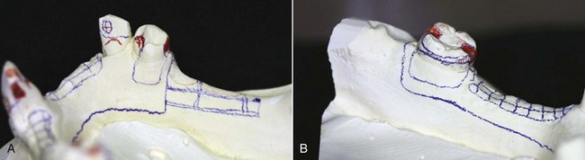
Figure 11-14 Diagnostic casts can serve as a visual guide for tooth preparation. A, Surveyed cast shows areas requiring tooth reduction in red (mesio-occlusal rest and distal guide plane #28, cingulum rest #27), as well as path of insertion tripod marks. B, This mesially tipped molar has been diagnosed to have a ring clasp. Red markings show the necessary mesio-occlusal and disto-occlusal rests required, as well as the mesial guide plane. Also shown is the reduction necessary to lower the lingual height of contour at the mesiolingual line angle. All required axial contour adjustments are determined through the appropriate use of a surveyor.
The surveyor blade, which represents the path of placement, may be used to advantage to trim the surface of the abutment tooth whenever a red mark appears. The resulting surface represents the amount of tooth to be removed in the mouth and indicates the angle at which the handpiece must be held. The cut surface on the stone tooth is not marked with red pencil again, but it is outlined in red pencil to positively locate the area that is to be prepared.
Recording Relation of Cast to Surveyor
Some method of recording the relation of the cast to the vertical arm of the surveyor must be used so that the cast may be returned to the surveyor for future reference, especially during mouth preparations. The same applies to the need for returning any working cast to the surveyor for shaping wax patterns, trimming blockout on the master cast, or locating clasp arms in relation to undercut areas.
Obviously the trimmed base will vary with each cast; therefore recording the position of the surveyor table is of no value. If it were, calibrations could be incorporated on the surveyor table that would allow the same position to be reestablished. Instead, the position of each cast must be established separately, and any positional record applies only to that cast.
Of several methods, two seem to be the most convenient and accurate. One method is to place three widely divergent dots on the tissue surface of the cast with the tip of a carbon marker with the vertical arm of the surveyor in a locked position. Preferably these dots should not be placed on areas of the cast involved in the framework design. The dots should be encircled with a colored pencil for easy identification. When the cast is returned to the surveyor, it may be tilted until the tip of the surveyor blade or diagnostic stylus again contacts the three dots in the same plane. This approach, which will produce the original position of the cast and therefore the original path of placement, is known as tripoding the cast (Figure 11-15). Some dentists prefer to make tiny pits in the cast at the location of the tripoding dots to preserve the orientation of the cast and to transfer this relationship to the refractory cast.
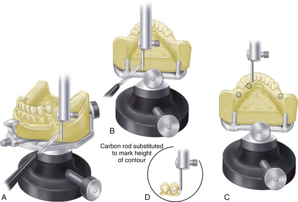
Figure 11-15 A-B, The path of placement is determined, and the base of the cast is scored to record its relation to the surveyor for future repositioning. C, An alternate method of recording the relation of the cast to the surveyor is known as tripoding. A carbon marker is placed in the vertical arm of the surveyor, and the arm is adjusted to the height by which the cast can be contacted in three divergent locations. The vertical arm is locked in position, and the cast is brought into contact with the tip of the carbon marker. Three resultant marks are encircled with colored lead pencil for ease of identification. Reorientation of the cast to the surveyor is accomplished by tilting the cast until the plane created by three marks is at a right angle to the vertical arm of the surveyor. D, Height of contour is then delineated by a carbon marker.
A second method is to score two sides and the dorsal aspect of the base of the cast with a sharp instrument held against the surveyor blade (see Figure 11-15). When the cast is tilted until all three lines are again parallel to the surveyor blade, the original cast position can be reestablished. Fortunately, the scratch lines will be reproduced in any duplication, thereby permitting any duplicate cast to be related to the surveyor in a similar manner. Whereas a diagnostic cast and a master cast cannot be made to be interchangeable, a refractory cast, which is a duplicate of the master cast, can be repositioned on the surveyor at any time. The technician must be cautioned not to trim the sides of the cast on the cast trimmer and thereby lose the reference marks for repositioning.
It must be remembered that repositioning a cast on a surveyor at any time can involve a certain amount of human error. It has been estimated that an error of 0.2 mm can be anticipated when a cast with three reference points on its base is reoriented. This reorientation error can influence the placement of appropriate blockout wax and may result in ineffective placement of direct retainers into prescribed undercuts and improper contacts of minor connectors with guiding planes. Therefore reorientation of the cast to the surveyor by any method must be done with great care.
Surveying the Master Cast
The master cast must be surveyed as a new cast, but the prepared proximal guiding plane surfaces will indicate the correct anteroposterior tilt. Some compromises may be necessary, but the amount of guiding plane surface remaining after blockout should be the maximum for each tooth. Areas above the point of contact with the surveyor blade are not considered as part of the guiding plane area, and neither are gingival undercut areas, which will be blocked out.
The lateral tilt will be the position that provides equal retentive areas on all principal abutments in relation to the planned clasp design. Factors of flexibility, including the need for extra flexibility on distal extension abutments, must be considered when one is deciding what will provide equal retention on all abutment teeth. For example, cast circumferential or cast bar retention on the tooth-supported side of a Class II design should be balanced against the 18-gauge wrought-wire retention on a distal abutment only if the more rigid cast clasp engages a lesser undercut than the wrought-wire clasp arm. Therefore the degree of undercut alone does not ensure relatively equal retention unless clasp arms of equal length, diameter, form, and material are used.
Gross interference will have been eliminated during mouth preparation. Thus for a given path of placement that is providing guiding planes and balanced retention, any remaining interference must be eliminated with blockout. If mouth preparations have been adequately planned and executed, the undercuts remaining to be blocked out should be minimal.
The base of the cast is now scored, or the cast is tripoded as described previously. The surveyor blade or diagnostic stylus then may be replaced with a carbon marker, and the height of convexity of each abutment tooth and soft tissue contours may be delineated. Similarly, any areas of interference to the rigid parts of the framework during seating and removal should be indicated with the carbon marker so areas to be blocked out or relieved can be located.
Carbon markers that become the slightest bit worn from use should be discarded. A worn (tapered) carbon marker will indicate heights of contour more occlusally located than those that actually exist. The carbon marker must be parallel to the vertical spindle of the surveyor (Figure 11-16). The diagnostic stylus should always be checked to ensure that it is not bent or distorted.
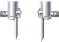
Figure 11-16 A worn carbon marker (left) should be discarded because it will invariably misleadingly mark the height of contour for a given orientation of the cast to the vertical spindle of the surveyor. Unworn carbon (right) with an angled end is preferable for marking heights of contour on abutment teeth and performing surveys of soft tissue areas.
Measuring Retention
The surveyor is used with the master cast for two purposes: (1) to delineate the height of contour of the abutment teeth both to locate clasp arms and to identify the location and magnitude of retentive undercuts; and (2) to trim blockout of any remaining interference to placement and removal of the denture. The areas involved are those that will be crossed by rigid parts of the denture framework.
The exact undercut that retentive clasp terminals will occupy must be measured and marked on the master cast (Figure 11-17). Undercuts may be measured with an undercut gauge, such as those provided with the Ney and Jelenko surveyors. The amount of undercut is measured in hundredths of an inch, with the gauges allowing measurements up to 0.03 inch. Theoretically the amount of undercut used may vary with the clasp to be used, up to a full 0.03 inch. However, undercuts of 0.01 inch are often adequate for retention by cast retainers. Tapered wrought-wire retention may safely use up to 0.02 inch without inducing undesirable torque on the abutment tooth, provided the wire retentive arm is long enough (at least 8 mm). The use of 0.03 inch is rarely, if ever, justified with any clasp. When greater retention is required, such as when abutment teeth remain on only one side of the arch, multiple abutments should be used, rather than increased retention on any one tooth.

Figure 11-17 A, Undercut gauge will measure the depth of undercut below the height of contour. I-bar direct retainer will contact the tooth from the point of the undercut to the height of contour. The depth to which the retentive clasp arm can be placed depends not only on its length, taper, and diameter and the alloy from which it is made, but also on the type of clasp. A circumferential clasp arm is more flexible than a bar clasp arm of the same length (see Chapter 7). B, Specific measurement of the undercut gingiva to the height of contour may be ascertained with the use of an undercut gauge attached to the surveyor. Simultaneous contact of the shank of the undercut gauge at the height of contour and of the lip of a specific undercut gauge on a tooth in the infrabulge area establishes definitively the degree and location of undercut. Therefore the tip of the retentive arm of the direct retainer may be placed at the planned depth of the undercut.
When a source of light is directed toward the tooth being surveyed, a triangle of light is visible. This triangle is bounded by the surface of the abutment tooth on one side and the blade of the surveyor on the other, the apex being the point of contact at the height of convexity and the base of the triangle being the gingival tissues (Figure 11-18). Retention will be determined by (1) the magnitude of the angle of cervical convergence below the point of convexity; (2) the depth at which the clasp terminal is placed in the angle; and (3) the flexibility of the clasp arm. The intelligent application of various clasp designs with their relative flexibility is of greater importance than the ability to measure an undercut with precise accuracy.
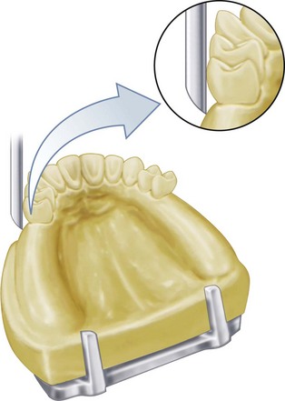
Figure 11-18 Tooth undercut is best viewed against a good source of light passing through the triangle bounded by the surface of the abutment tooth, the surveyor blade, and the gingival tissues.
The final design may now be drawn on the master cast with a fine crayon pencil, preferably one that will not come off during duplication. Graphite is usually lifted in duplication, but some crayon pencil marks will withstand duplication without blurring or transfer. Sizing or spraying the master cast to protect such pencil marks is usually not advisable unless it is done with extreme care to avoid obliterating the surface detail.
Blocking Out the Master Cast
After the path of placement and the location of undercut areas have been established on the master cast, any undercut areas that will be crossed by rigid parts of the denture (which is every part of the denture framework but the retentive clasp terminals) must be eliminated by blockout.
In the broader sense of the term, blockout includes not only the areas crossed by the denture framework during seating and removal but also (1) those areas not involved that are blocked out for convenience; (2) ledges on which clasp patterns are to be placed; (3) relief beneath connectors to avoid tissue impingement; and (4) relief to provide for attachment of the denture base to the framework.
Ledges or shelves (shaped blockout) for locating clasp patterns may or may not be used (Figure 11-19). However, this should not be confused with the actual blocking out of undercut areas that would offer interference to the placement of the denture framework. Only the latter is made on the surveyor, with the surveyor blade or diagnostic stylus used as a paralleling device.
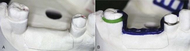
Figure 11-19 The wax ledge on the buccal surface of the molar abutment will be duplicated in a refractory cast for exact placement of the clasp pattern. Note that the ledge has been carved slightly below the penciled outline of the clasp arm. This will allow the gingival edge of the clasp arm to be polished and still remain in its planned relationship to the tooth when the denture is seated. It should also be noted that the wax ledge definitively establishes planned placement of the direct retainer tip into the measured undercut.
Hard inlay wax may be used satisfactorily as a blockout material. It is easily applied and is easily trimmed with the surveyor blade. Trimming is facilitated by slight warming of the surveyor blade with an alcohol torch. Whereas it is true that any wax will melt more readily than a wax-clay mixture if the temperature of the duplicating material is too high, it should be presumed that the duplicating material will not be used at such an elevated temperature. If the temperature of the duplicating material is high enough to damage a wax blockout, other distortions resulting in an inaccurate duplication will likely occur.
Paralleled blockout is necessary for areas that are cervical to guiding-plane surfaces and over all undercut areas that will be crossed by major or minor connectors. Other areas that are to be blocked out for convenience and for avoidance of difficulties in duplication should be blocked out with hard baseplate wax or oil-base modeling clay (artist’s modeling clay). Such areas include the labial surfaces and labial undercuts not involved in the denture design and the sublingual and distolingual areas beyond the limits of the denture design. These are blocked out arbitrarily with hard baseplate wax or clay, but because they have no relation to the path of placement, they do not require the use of the surveyor. Modeling clay that is water soluble should not be used when duplication procedures are involved.
Areas to be crossed by rigid connectors, on the other hand, should be trimmed with the surveyor blade or some other surveyor tool parallel to the path of placement (Figure 11-20). This imposes a considerable responsibility on the technician. If the blockout is not sufficiently trimmed to expose guiding-plane surfaces, the effects of these guiding planes, which were carefully established by the dentist, will be nullified. If, on the other hand, the technician is overzealous in paralleling the blockout, the stone cast may be abraded by heavy contact with the surveyor blade. Although the resulting cast framework would seat back onto the master cast without interference, interference to placement in the mouth would result. This would necessitate relieving the casting at the chair, which is not only an embarrassing and time-consuming operation but also one that may have the effect of obliterating guiding plane surfaces.
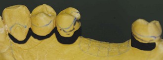
Figure 11-20 All guiding-plane areas must be parallel to the path of placement, and all other areas that will be contacted by rigid parts of the denture framework must be made free of the undercut by parallel blockout. Relief must also be provided for the gingival crevice and gingival margin. Black regions designate parallel blockout at proximal guide-plane surfaces and relief along the palatal marginal gingiva.
Relieving the Master Cast
Tissue undercuts that must be blocked out are paralleled in much the same manner as tooth undercuts. The difference between blockout and relief must be clearly understood (Figures 11-21 and 11-22). For example, tissue undercuts that would offer interference to the seating of a lingual bar connector are blocked out with blockout wax and trimmed parallel to the path of placement. This does not in itself necessarily afford relief to avoid tissue impingement. In addition to such blockout, a relief of varying thickness must sometimes be used, depending on the location of the connector, the relative slope of the alveolar ridge, and the predictable effect of denture rotation. It must be assumed that indirect retainers, as such, or indirect retention is provided in the design of the denture to prevent rotation of the lingual bar inferiorly. A vertical downward rotation of the denture bases around posterior abutments places the bar increasingly farther from the lingual aspect of the alveolar ridge when this surface slopes inferiorly and posteriorly (Figure 11-23). Adequate relief of soft tissues adjacent to the lingual bar is obtained by the initial finishing and polishing of the framework in these instances. However, excessive upward vertical rotation of a lingual bar will impinge on lingual tissues if the alveolar ridge is nearly vertical or undercut to the path of placement (Figure 11-24). The region of the cast involving proposed placement of the lingual bar should, in this situation, be relieved first by parallel blockout and then by a 32-gauge wax strip. Low-fusing casting wax such as Kerr’s green casting wax should not be used for this purpose: it is too easily thinned during adapting and may be affected by the temperature of the duplicating material. Pink casting wax should be used, even though it is difficult to adapt uniformly. A pressure-sensitive, adhesive-coated casting wax is preferred because it adapts readily and adheres to the cast surface. Any wax, even the adhesive type, should be sealed all around its borders with a hot spatula to prevent its lifting when the cast is moistened before or during duplication.
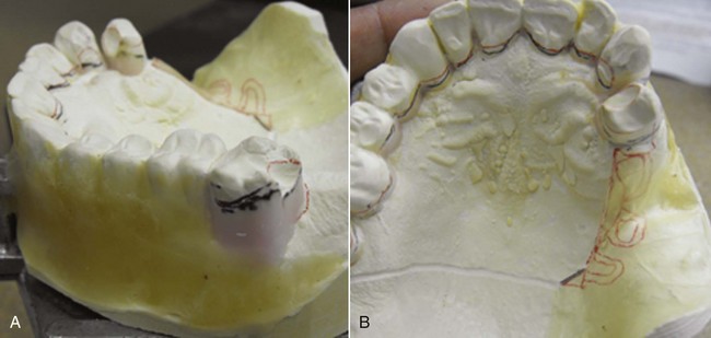
Figure 11-21 Parallel blockout (A, labial surfaces of all teeth and gingivae to the retentive clasp on tooth #2) and relief (B, marginal gingivae of palatal surfaces of teeth and at distal minor connector) in preparation for framework casting. These spaces allow planned seating of the framework without tissue trauma while accommodating the addition of acrylic-resin beneath the distal extension minor connector for base support without metal contact.
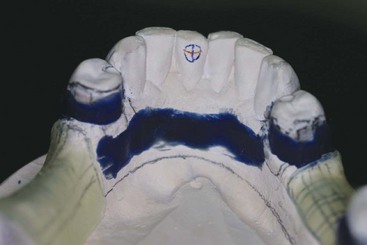
Figure 11-22 Relief and blockout of the master cast before duplication. All undercuts involved in the denture design have been blocked out parallel to the path of placement, except the retentive tips of the retainer clasps. Residual ridges have been provided 20-gauge relief for denture base material.
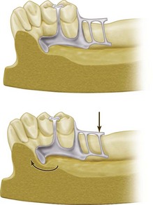
Figure 11-23 Sagittal section of the cast and denture framework. The lingual alveolar ridge slopes inferiorly and posteriorly (upper figure). When the force is directed to displace the denture base downward, the lingual bar rotates forward and upward but does not impinge on the soft tissue of the alveolar ridge (lower figure). Therefore in such instances, adequate relief to avoid impingement is gained when the tissue side of the lingual bar is highly polished during the finishing process.
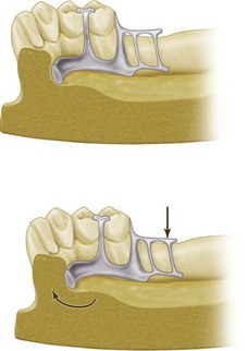
Figure 11-24 An undercut alveolar ridge was blocked out parallel to the path of placement in fabricating the lingual bar (upper figure). Application of vertical force to cause rotation of the lingual bar upward can cause impingement of lingual tissue on the alveolar ridge (lower figure). To avoid impingement in these instances, not only should the master cast be blocked out parallel to the path of placement, but an additional relief of 32-gauge sheet wax should be used to block out the cast in such undercut areas.
Horizontal rotational tendencies of mandibular distal extension removable partial dentures account for many of the tissue irritations seen adjacent to a lingual mandibular major connector. These irritations can usually be avoided by blocking out all undercuts adjacent to the bar parallel to the path of placement and then including adequate stabilizing components in the design of the framework to resist horizontal rotation. Judicious relief of the tissue side of the lingual bar with rubber wheels at the site of the irritation most often will correct the discrepancy. Under no circumstances should the rigidity of the major connector be jeopardized by grinding any portion of it.
Still other areas requiring relief are the areas where component parts cross the gingiva and gingival crevices. All gingival areas bridged by the denture framework should be protected from possible impingement resulting from rotation of the denture framework. Hard inlay wax may be used to block out gingival crevices (see Figure 11-21).
Paralleled Blockout, Shaped Blockout, Arbitrary Blockout, and Relief
Table 11-1 differentiates between paralleled blockout, shaped blockout, arbitrary blockout, and relief. The same factors apply to both maxillary and mandibular arches, except that relief is ordinarily not used beneath palatal major connectors, as it is with mandibular lingual bar connectors, except when maxillary tori cannot be circumvented, or when resistive median palatal raphes are encountered.
Table 11-1 Differentiation Between Parallel Blockout, Shaped Blockout, Arbitrary Blockout, and Relief
| Site | Material | Thickness |
|---|---|---|
| Parallel Blockout | ||
| Proximal tooth surfaces to be used as guiding planes | Hard baseplate wax or blockout material | Only undercut remaining below contact of the surveyor blade with tooth surface |
| Beneath all minor connectors | Hard baseplate wax or blockout material | Only undercut remaining below contact of the surveyor blade with tooth surface |
| Tissue undercuts to be crossed by rigid connectors | Hard baseplate wax or blockout material | Only undercut remaining below contact of the surveyor blade with surface of the cast |
| Tissue undercuts to be crossed by the origin of bar clasps | Hard baseplate wax or blockout material | Only undercut remaining below contact of the surveyor blade with surface of the cast |
| Deep interproximal spaces to be covered by minor connectors or linguoplates | Hard baseplate wax or blockout material | Only undercut remaining below contact of the surveyor blade with surface of the cast |
| Beneath bar clasp arms to gingival crevice | Hard baseplate wax or blockout material | Only undercut area involved in attachment of the clasp arm to the minor connector |
| Shaped Blockout | ||
| On buccal and lingual surfaces to locate plastic or wax patterns for clasp arms | Hard baseplate wax | Ledges for location of reciprocal clasp arms to follow height or convexity so that they may be placed as cervical as possible without becoming retentive |
| Ledges for location of retentive clasp arms to be placed as cervical as tooth contour permits; point of origin of clasp to be occlusal or incisal to height of the convexity, crossing the survey line at fourth terminal, and to include undercut area previously selected in keeping with flexibility of the clasp type being used | ||
| Arbitrary Blockout | ||
| All gingival crevices | Hard baseplate wax | Enough to just eliminate gingival crevice |
| Gross tissue undercuts situated below areas involved in the design of denture framework | Hard baseplate wax or oil-based clay | Leveled arbitrarily with a wax spatula |
| Tissue undercuts distal to the cast framework | Hard baseplate wax or oil-based clay | Smoothed arbitrarily with a wax spatula |
| Labial and buccal tooth and tissue undercuts not involved in denture design | Hard baseplate wax or oil-based clay | Filled and tapered with spatula to within the upper third or crown |
| Relief | ||
| Beneath lingual bar connectors or the bar portion of the linguoplates when indicated (see text) | Adhesive wax sealed to the cast; should be wider than the major connector to be placed on it | 32-Gauge wax if the slope of the lingual alveolar ridge is parallel to the path of placement; 32-gauge wax after parallel blockout of undercuts if the slope of the lingual alveolar ridge is undercut to the path of placement |
| Areas in which major connectors will contact thin tissue, such as hard areas so frequently found on lingual or mandibular ridges and elevated palatal raphes | Hard baseplate wax | Thin layer flowed on with hot wax spatula; however, if the maxillary torus must be covered, the thickness of the relief must represent the difference in the degree of displacement of the tissues covering the torus and the tissues covering the residual ridges |
| Beneath framework extensions onto ridge areas for attachment of resin bases | Adhesive wax, well adapted to and sealed to the cast beyond the involved area | 20-Gauge wax |