CHAPTER 7 Direct Retainers
Direct Retainer’s Role in Control of Prosthesis Movement
Retention of a removable prosthesis is a unique concern when compared with other prostheses. When one is dealing with a crown or fixed partial denture, the combined use of preparation geometry (i.e., resistance and retention form) and a luting agent can fix the prosthesis to the tooth in a manner that resists all forces to which the teeth are subjected. As was mentioned in Chapter 4, the direction of forces can be toward, across, or away from the tissue. In general, the forces acting to move prostheses toward and across the supporting teeth and/or tissue are the greatest in intensity. This is because most often they are forces of occlusion.
Forces acting to displace the prosthesis from the tissue can consist of gravity acting against a maxillary prosthesis, the action of adherent foods acting to displace the prosthesis on opening of the mouth in chewing, or functional forces acting across a fulcrum to unseat the prosthesis. The first two of these forces are seldom at the magnitude of functional forces, and the latter is minimized through the use of adequate support. The component part applied to resist this movement away from the teeth and/or tissue provides retention for the prosthesis and is called the direct retainer. A direct retainer is any unit of a removable dental prosthesis that engages an abutment tooth or implant to resist displacement of the prosthesis away from basal seat tissue. The direct retainer’s ability to resist this movement is greatly influenced by the stability and support of the prosthesis provided by major and minor connectors, rests, and tissue bases. This relationship of the supportive and retentive components highlights the relative importance of these component parts. Although the forces working against a removable partial denture to move it away from the tissue generally are not as great as the functional forces causing stress toward the tissue, the removable partial denture must have retention appropriate to resist reasonable dislodging forces. Too often retention concerns are given greater importance than is appropriate, especially if such a focus detracts from more serious consideration of the resistance of typical functional forces.
Sufficient retention is provided by two means. Primary retention for the removable partial denture is accomplished mechanically by placing retaining elements (direct retainers) on the abutment teeth. Secondary retention is provided by the intimate relationship of the minor connector contact with the guiding planes and denture bases, and of the major connector (maxillary) with underlying tissue. The latter is similar to the retention of a complete denture. It is proportionate to the accuracy of the impression registration, the accuracy of the fit of the denture bases, and the total involved area of contact. Retention can also be provided through engagement of an attachment mechanism on a dental implant.
Basic Principles of Clasp Design
The clasp assembly serves a similar function for a removable partial denture that a retainer crown serves for a fixed partial denture. Both must encircle the prepared tooth in a manner that prevents movement of the tooth separate from the retainer. To borrow from a fixed prosthodontic term, limiting the freedom of displacement refers to the effect of one cylindrical surface (the framework encircling the tooth) on another cylindrical surface (the tooth). It implies that the curve that defines the framework is properly shaped if it prevents movement at right angles to the tooth axis. This basic principle of clasp design offers a two-way benefit. First, it ensures the stability of the tooth position because of the restraint from encirclement, and second, it ensures stability of the clasp assembly because of the controlled position of the clasp in three dimensions.
Therefore the basic principle of clasp design, referred to as the principle of encirclement, means that more than 180 degrees in the greatest circumference of the tooth, passing from diverging axial surfaces to converging axial surfaces, must be engaged by the clasp assembly (Figure 7-1). The engagement can occur in the form of continuous contact, such as in a circumferential clasp, or discontinuous contact, such as in the use of a bar clasp. Both provide tooth contact in at least three areas encircling the tooth: the occlusal rest area, the retentive clasp terminal area, and the reciprocal clasp terminal area.
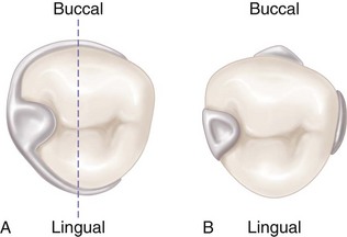
Figure 7-1 A, Line drawn through the illustration represents 180 degrees of greatest circumference of abutment from the occlusal rest. Unless portions of the lingual reciprocal arm and the retentive buccal arm are extended beyond the line, the clasp would not accomplish its intended purpose. If respective arms of the retainer were not extended beyond the line, the abutment tooth could be forced away from the retainer through torquing action of the clasp, or the removable partial denture could move away from the abutment. B, Bar-type clasp assembly engagement of more than 180 degrees of circumference of the abutment is realized by the minor connector for the occlusal rest, the minor connector contacting the guiding plane on the distal proximal surface, and the retentive bar arm.
In addition to encirclement, other basic principles of clasp design are as follows:
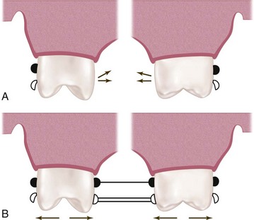
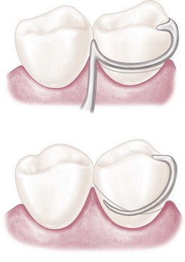
Figure 7-2 A, Flexing action of the retentive clasp arm initiates medially directed pressure on the abutment teeth as its retentive tip springs over the height of contour. B, Reciprocation to medially directed pressure is counteracted by rigid lingually placed clasp arms contacting the abutments simultaneously with the buccal arms, or by rigid stabilizing components of the framework contacting the lingual guiding planes when the buccal arms begin to flex.
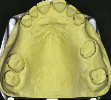
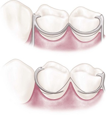
Figure 7-3 Retentive clasps should be bilaterally opposed. This means bilateral buccal or bilateral lingual undercuts should be used, as shown on this Class III, modification 2 arch, in which the retention may be (a) bilaterally buccal or (b) bilaterally lingual.
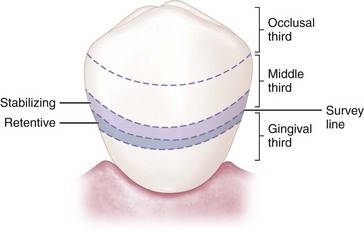
Figure 7-4 Simple mechanical laws demonstrate that the nearer stabilizing-reciprocal and retentive elements of direct retainer assemblies are located horizontal to the axis of rotation of the abutment, the less likely it is that physiologic tolerance of the periodontal ligament will be exceeded. The horizontal axis of rotation of the abutment tooth is located somewhere in its root.
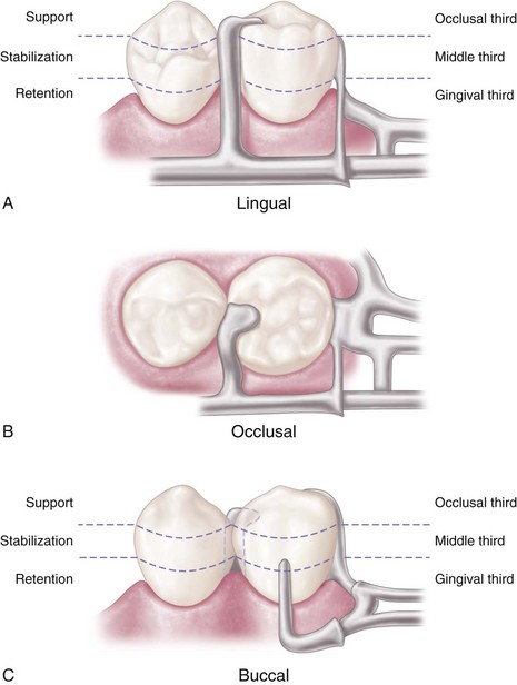
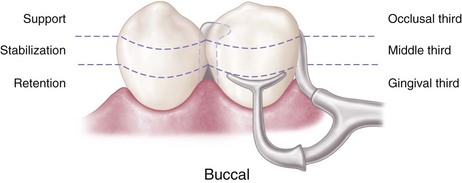
Figure 7-5 A bar-type clasp on the mandibular premolar. A, Support is provided by the occlusal rest. B, Stabilization is provided by the occlusal rest and the mesial and distal minor connectors. C, Retention is provided by the buccal I-bar. Reciprocation is obtained through the location of the minor connectors. Engagement of more than 180 degrees of circumference of the abutment is accomplished by proper location of components contacting the axial surfaces. (The minor connector supports the occlusal rest, the proximal plate minor connector, and the buccal I-bar.)
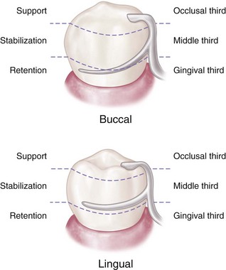
Figure 7-6 Circumferential clasp on the mandibular premolar. Support is provided by the occlusal rest; stabilization is provided by the occlusal rest, proximal minor connector, lingual clasp arm, and rigid portion of the buccal retentive clasp arm occlusal to the height of contour; retention is realized by the retentive terminal of the buccal clasp arm; reciprocation is provided by the nonflexible lingual clasp arm. Assembly engages more than 180 degrees of the abutment tooth’s circumference.
Reciprocal Arm Functions
As was mentioned earlier, reciprocal arms are intended to resist tooth movement in response to deformation of the retainer arm as it engages a tooth height of contour. The opposing clasp arm reciprocates the effect of this deformation as it prevents tooth movement. For this to occur, the reciprocal arm must be in contact during the time of retainer arm deformation. Unless the abutment tooth has been specifically contoured, the reciprocal clasp arm will not come into contact with the tooth until the denture is fully seated and the retentive clasp arm has again become passive. When this happens, a momentary tipping force is applied to the abutment teeth during each placement and removal. This may not be a damaging force—because it is transient—so long as the force does not exceed the normal elasticity of the periodontal attachments. True reciprocation during placement and removal is possible only through the use of crown surfaces made parallel to the path of placement. The use of cast restorations permits the parallel surfaces to be contacted by the reciprocal arm in such a manner that true reciprocation is made possible. This is discussed in Chapter 14.
Reciprocal arms can have additional functions as well. The reciprocal clasp arm should be located so that the denture is stabilized against horizontal movement. Stabilization is possible only through the use of rigid clasp arms, rigid minor connectors, and a rigid major connector. Horizontal forces applied on one side of the dental arch are resisted by the stabilizing components on the opposite side, providing cross-arch stability. Obviously the greater the number of such components, within reason, the greater will be the distribution of horizontal stresses.
The reciprocal clasp arm also may act to a minor degree as an indirect retainer. This is true only when it rests on a suprabulge surface of an abutment tooth lying anterior to the fulcrum line (see Figure 8-8). Lifting of a distal extension base away from the tissue is thus resisted by a rigid arm, which is not easily displaced cervically. The effectiveness of such an indirect retainer is limited by its proximity to the fulcrum line, which gives it a relatively poor leverage advantage, and by the fact that slippage along tooth inclines is always possible. The latter may be prevented by the use of a ledge on a cast restoration; however, enamel surfaces are not ordinarily so prepared.
Types of Direct Retainers
Mechanical retention of removable partial dentures is accomplished by means of direct retainers of one type or another. Retention is accomplished by using frictional means, by engaging a depression in the abutment tooth, or by engaging a tooth undercut lying cervically to its height of contour. Two basic types of direct retainers are available: the intracoronal retainer and the extracoronal retainer. The extracoronal (clasp-type) retainer is the most commonly used retainer for removable partial dentures.
The intracoronal retainer may be cast or may be attached totally within the restored natural contours of an abutment tooth. It is typically composed of a prefabricated machined key and keyway with opposing vertical parallel walls, which serve to limit movement and resist removal of the partial denture through frictional resistance (Figure 7-7). The intracoronal retainer is usually regarded as an internal, or precision, attachment. The principle of the internal attachment was first formulated by Dr. Herman E.S. Chayes in 1906.
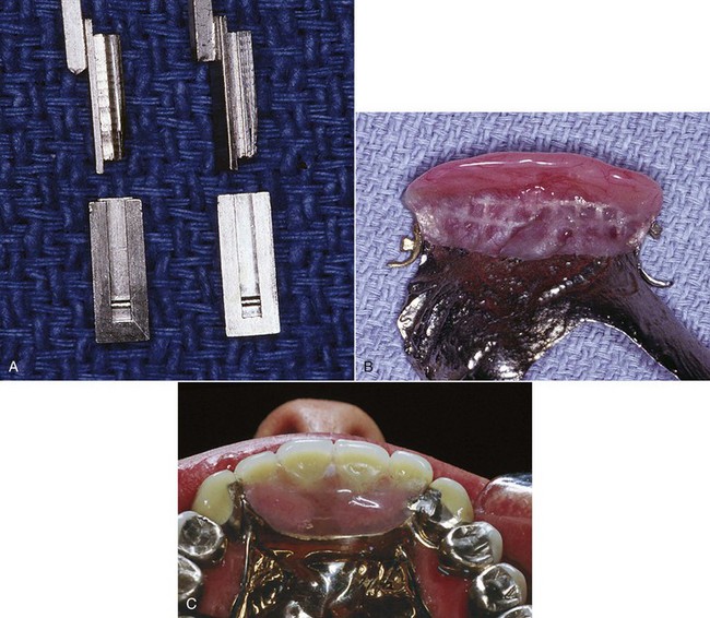
Figure 7-7 A, The intracoronal retainer consists of a key and keyway with extremely small tolerance. Keyways are contained within abutment crowns, and (B) keys are attached to the removable partial denture framework. C, Frictional resistance to removal and placement and limitation of movement serve to retain and stabilize the prosthesis.
The extracoronal retainer uses mechanical resistance to displacement through components placed on or attached to the external surfaces of an abutment tooth. The extracoronal retainer is available in three principal forms. The clasp-type retainer (Figures 7-8 and 7-9), the form used most commonly, retains through a flexible clasp arm. This arm engages an external surface of an abutment tooth in an area cervical to the greatest convexity of the tooth, or it engages a depression prepared to receive the terminal tip of the arm. The other forms both involve manufactured attachments and include interlocking components or the use of a spring-loaded device that engages a tooth contour to resist occlusal displacement. Another type is a manufactured attachment, which uses flexible clips or rings that engage a rigid component that is cast or attached to the external surface of an abutment crown.
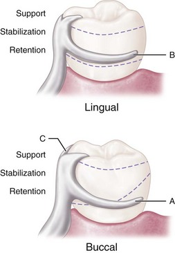
Figure 7-8 Extracoronal circumferential direct retainer. Assembly consists of (A) the buccal retentive arm; (B) the rigid lingual stabilizing (reciprocal) arm; and (C) the supporting occlusal rest. The terminal portion of the retentive arm is flexible and engages measured undercut. Assembly remains passive until activated by placement or removal of the restoration, or when subjected to masticatory forces that tend to dislodge the denture base.
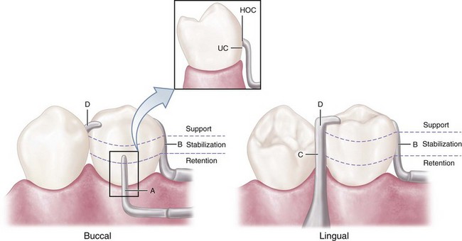
Figure 7-9 Extracoronal bar-type direct retainer. Assembly consists of (A) the buccal retentive arm engaging the measured undercut (with slight occlusal extension for stabilization, see insert where HOC is height of contour and UC is undercut); (B) the stabilizing (reciprocal) elements, with the proximal plate minor connector on the distal; (C) the lingually placed mesial minor connector for the occlusal rest, which also serves as a stabilizing (reciprocal) component; and (D) the mesially placed supporting occlusal rest. Assembly remains passive until activated.
In situations where support requirements are adequately met by available teeth and/or oral tissues, dental implants can be used for retention and provide the advantage of elimination of a visible clasp.
Criteria for Selecting a Given Clasp Design
When a particular clasp design is selected for a given situation, its function and limitations must be carefully evaluated. Extracoronal direct retainers, as part of the clasp assembly, should be considered as components of a removable partial denture framework. They should be designed and located to perform the specific functions of support, stabilization, reciprocation, and retention. It does not matter whether the direct retainer-clasp assembly components are physically attached to each other, or originate from major and minor connectors of the framework (see Figures 1-2 and 1-3, B-E). If attention is directed to the separate function of each component of the direct retainer-clasp assembly, then selection of a direct retainer is simplified.
Although some rather complex designs are used for clasp arms, they all may be classified into one of two basic categories. One is the circumferential clasp arm, which approaches the retentive undercut from an occlusal direction. The other is the bar clasp arm, which approaches the retentive undercut from a cervical direction. A clasp assembly may comprise various retentive arms (i.e., a cast circumferential, a bar clasp arm, or a wrought-wire retainer), depending on the specific requirement for retainer construction, given the necessary adjustability, clasp approach position, and survey line location.
A clasp assembly should consist of four component parts. First, one or more minor connectors should be present, from which the clasp components originate. Second, a principal rest should be designed to direct stress along the long axis of the tooth. Third, a retentive arm should engage a tooth undercut. For most clasps, the retentive region is only at its terminus. Fourth, a nonretentive arm (or other component) should be present on the opposite side of the tooth for stabilization and reciprocation against horizontal movement of the prosthesis (rigidity of this clasp arm is essential to its purpose).
No confusion should exist between the choice of clasp arm and the purpose for which it is used. Either type of cast clasp arm (bar or circumferential) may be made tapered and retentive, or nontapered (rigid) and nonretentive. The choice depends on whether it is used for retention, stabilization, or reciprocation. An occlusal rest, such as in the RPI (rest, proximal plate, and I-bar component parts of the clasp assembly) concept, may be used rather than a reciprocal clasp arm to satisfy the need for encirclement, provided it is located in such a way that it can accomplish the same purpose (Figure 7-10; see also Figure 7-9). The addition of a lingual apron to a cast reciprocal clasp arm alters neither its primary purpose nor the need for proper location to accomplish that purpose.
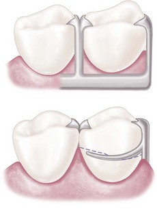
Figure 7-10 The auxiliary occlusal rest (mirror view) may be used rather than the reciprocal clasp arm without violating any principle of clasp design. Its greatest disadvantages are that the second rest seat must be prepared, and that enclosed tissue space at the gingival margin can result in a food trap. The auxiliary occlusal rest is also sometimes used to prevent slippage when the principal occlusal rest seat cannot be inclined apically from the marginal ridge. Minor connectors used to close the interproximal space most often require rests on adjacent teeth to avoid a wedging effect when force is placed on the denture.
Types of Clasp Assemblies
A wide variety of clasp assemblies are available for clinicians to use. This variety exists largely because of the imagination of clinicians and technicians who provided prostheses when tooth modification was not or could not be provided. To simplify clasp design and to improve the functional predictability of prostheses, today’s clinician must realize the need for tooth modification.
Some clasp assemblies are designed to accommodate prosthesis functional movement (as mentioned in the basic principles above), and others do not incorporate such design features. Although it has been demonstrated by Kapur and others that adverse outcomes are not always associated with the use of rigid clasp assemblies in distal extension classifications, the following clasp assemblies will be described as clasps designed to accommodate distal extension functional movement and clasps designed without movement accommodation. The clinician should not interpret these categories as mutually exclusive because most any clasp assembly can be used to retain a well-supported and maintained prosthesis.
Clasps Designed to Accommodate Functional Movement
RPI, RPA, and Bar Clasp
Clasp assemblies that accommodate functional prosthesis movement are designed to address the concern of a Class I lever. The concern is that the distal extension acts as a long “effort arm” across the distal rest “fulcrum” to cause the clasp tip “resistance arm” to engage the tooth undercut. This results in harmful tipping or torquing of the tooth, which is greater with stiff clasps and increased denture base movement. Two strategies may be adopted to change the fulcrum location and subsequently the “resistance arm” engaging effect (mesial rest concept clasp assemblies), or to minimize the effect of the lever through the use of a flexible arm (wrought-wire retentive arm).
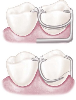
Mesial rest concept clasps have been proposed to accomplish movement accommodation by changing the fulcrum location. This concept includes the RPI and RPA [rest, proximal plate, Akers] clasps. The RPI is a current concept of bar clasp design that refers to the rest, proximal plate, and I-bar component parts of the clasp assembly. Basically, this clasp assembly consists of a mesio-occlusal rest with the minor connector placed into the mesiolingual embrasure, but not contacting the adjacent tooth (Figure 7-11, A). A distal guiding plane, extending from the marginal ridge to the junction of the middle and gingival thirds of the abutment tooth, is prepared to receive a proximal plate (Figure 7-11, B). The buccolingual width of the guiding plane is determined by the proximal contour of the tooth (Figure 7-11, A and C). The proximal plate, in conjunction with the minor connector supporting the rest, provides the stabilizing and reciprocal aspects of the clasp assembly. The I-bar should be located in the gingival third of the buccal or labial surface of the abutment in a 0.01-inch undercut (Figure 7-11, D). The whole arm of the I-bar should be tapered to its terminus, with no more than 2 mm of its tip contacting the abutment. The retentive tip contacts the tooth from the undercut to the height of contour (Figure 7-11, E). This area of contact, along with the rest and proximal plate contact, provides stabilization through encirclement (see Figure 7-11, C). The horizontal portion of the approach arm must be located at least 4 mm from the gingival margin and even farther if possible.
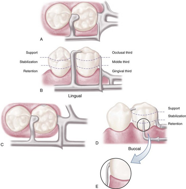
Figure 7-11 Bar-type clasp assembly. A, Occlusal view. Component parts (proximal plate minor connector, rest with minor connector, and retentive arm) tripod the abutment to prevent its migration. B, The proximal plate minor connector extends just far enough lingually so that it combines with the mesial minor connector to prevent lingual migration of the abutment. C, On narrow or tapered abutments (mandibular first premolars), the proximal plate should be designed to be as narrow as possible but still sufficiently wide to prevent lingual migration. D, I-bar retainer located at greatest prominence of tooth in the gingival third. E, Mesial view of I-bar illustrating the retentive tip relationship to the undercut and a region superior to the height of contour, which serves a stabilization function in encirclement.
Three basic approaches to the application of the RPI system may be used. The location of the rest, the design of the minor connector (proximal plate) as it relates to the guiding plane, and the location of the retentive arm are factors that influence how this clasp system functions. Variations in these factors provide the basis for differences among these approaches. All advocate the use of a rest located mesially on the primary abutment tooth adjacent to the extension base area. One approach recommends that the guiding plane and the corresponding proximal plate minor connector should extend the entire length of the proximal tooth surface, with physiologic tissue relief eliminating impingement of the free gingival margin (Figure 7-12). A second approach suggests that the guiding plane and the corresponding proximal plate minor connector should extend from the marginal ridge to the junction of the middle and gingival thirds of the proximal tooth surface (Figure 7-13). Both approaches recommend that the retaining clasp arm should be located in the gingival third of the buccal or labial surface of the abutment in a 0.01-inch undercut. Placement of the retaining clasp arm generally occurs in an undercut located at the greatest mesiodistal prominence of the tooth or adjacent to the extension base area (Figure 7-14, A and B). The third approach favors a proximal plate minor connector that contacts approximately 1 mm of the gingival portion of the guiding plane (Figure 7-15, A) and a retentive clasp arm located in a 0.01-inch undercut in the gingival third of the tooth at the greatest prominence or toward the mesial away from the edentulous area (Figure 7-14, C). If the abutment teeth demonstrate contraindications for a bar-type clasp (i.e., exaggerated buccal or lingual tilts, severe tissue undercut, or a shallow buccal vestibule) and the desirable undercut is located in the gingival third of the tooth away from the extension base area, a modification should be considered for the RPI system (the RPA clasp) (Figure 7-15, B). Application of each approach is predicated on the distribution of load to be applied to the tooth and edentulous ridge.
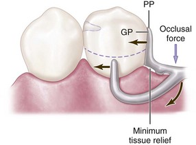
Figure 7-12 Bar clasp assembly in which the guiding plane (GP) and the corresponding proximal plate (PP) extend the entire length of the proximal tooth surface. Physiologic relief is required to prevent impingement of the gingival tissues during function. Extending the proximal plate to contact a greater surface area of the guide plane directs functional forces in a horizontal direction, thus the teeth are loaded to a greater extent than the edentulous ridge.
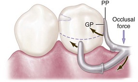
Figure 7-13 Bar clasp assembly in which the guiding plane (GP) and the corresponding proximal plate (PP) extend from the marginal ridge to the junction of the middle and gingival thirds of the proximal tooth surface. This decrease (compared with Figure 7-23) in amount of surface area contact of the proximal plate on the guiding plane more evenly distributes functional force between the tooth and the edentulous ridge.
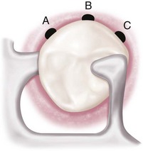
Figure 7-14 Occlusal view of the RPI (rest, proximal plate, and I-bar component parts) bar clasp assembly. Placement of the I-bar in a 0.01-inch undercut (A) on the distobuccal surface; (B) at the greatest mesiodistal prominence; and (C) on the mesiobuccal surface.
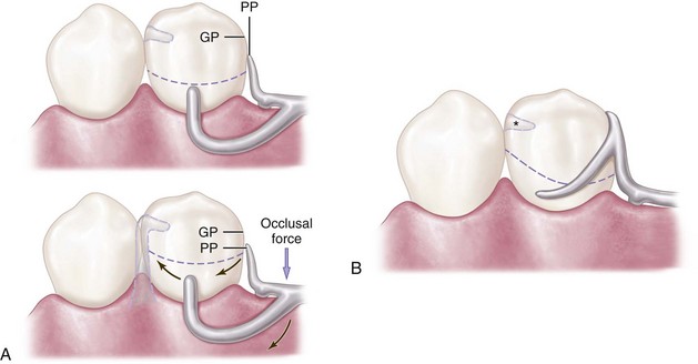
Figure 7-15 A, Bar clasp assembly in which the proximal plate (PP) contacts approximately 1 mm of the gingival portion of the guiding plane (GP). During function, the proximal plate and the I-bar clasp arm are designed to move in a mesiogingival direction, disengaging the tooth. Lack of sustained contact between the proximal plate and the guiding plane distributes increased functional force to the edentulous ridge. Asterisk (*) indicates center of rotation. B, Modification of the RPI (rest, proximal plate, and I-bar component parts) system (rest, proximal plate, Akers or RPA clasp) is indicated when a bar-type clasp is contraindicated and a desirable undercut is located in the gingival third of the tooth away from the extension base area.
The bar clasp, which gave rise to the RPI, is discussed here because of this association. It may not be configured to allow functional movement, but it can be. The term bar clasp is generally preferred over the less descriptive term Roach clasp arm. Reduced to its simplest term, the bar clasp arm arises from the denture framework or a metal base and approaches the retentive undercut from a gingival direction (see Figure 7-11). The bar clasp arm has been classified by the shape of the retentive terminal. Thus it has been identified as a T, modified T, I, or Y. The form the terminal takes is of little significance as long as it is mechanically and functionally effective, covers as little tooth surface as possible, and displays as little metal as possible.
In most situations, the bar clasp arm can be used with tooth-supported partial dentures, with tooth-supported modification areas, or when an undercut that can be logically approached with a bar clasp arm lies on the side of an abutment tooth adjacent to a distal extension base (Figure 7-16). If a tissue undercut prevents the use of a bar clasp arm, a mesially originating ring clasp, a cast, or a wrought-wire clasp or reverse-action clasp may be used. Preparation of adjacent abutments (natural teeth) to receive any type of interproximal direct retainer, traversing from lingual to buccal surfaces, is most difficult to adequately accomplish. Inevitably the relative size of the occlusal table is increased, contributing to undesirable and additional functional loading.
Figure 7-16 Bar clasp arm properly used on the terminal abutment. The combination of rest, proximal plate, and bar clasp contacting the abutment tooth provides more than 180 degrees encirclement. A uniform taper to the bar ensures proper flexibility and internal stress distribution. Taper can originate from the minor connector junction or at a finishing line indicating the anterior extent of the denture base. Encirclement does not require that retentive tip modification (in the form of a T) be provided, and such a modification adds little to the clasp assembly.
Specific indications for use of a bar clasp arm include (1) when a small degree of undercut (0.01 inch) exists in the cervical third of the abutment tooth, which may be approached from a gingival direction; (2) on abutment teeth for tooth-supported partial dentures or tooth-supported modification areas (Figure 7-17); (3) in distal extension base situations; and (4) in situations in which esthetic considerations must be accommodated and a cast clasp is indicated. Thus use of the bar clasp arm is contraindicated when a deep cervical undercut exists or when a severe tooth and/or tissue undercut exists, either of which must be bridged by excessive blockout. When severe tooth and tissue undercuts exist, a bar clasp arm usually is an annoyance to the tongue and cheek and may traps food debris. Other limiting factors in the selection of a bar clasp assembly include a shallow vestibule or an excessive buccal or lingual tilt of the abutment tooth (Figure 7-18). Some common errors in the design of bar-type clasps are illustrated in Figure 7-19.
Figure 7-17 A bar retainer is used on the anterior abutment of the modification space, and its terminus engages the distobuccal undercut. The denture is designed to rotate around the terminal abutments when force is directed toward the basal seat on the left. Such rotation would impart force on the right premolar directed superiorly and anteriorly. However, this direction of force is resisted in great part by mesial contact with the canine. A direct retainer on the right premolar engaging the mesiobuccal undercut would tend to force the tooth superiorly and posteriorly.
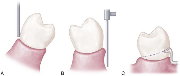
Figure 7-18 Contraindications for selection of bar-type clasps. A, Severe buccal or lingual tilts of abutment teeth. B, Severe tissue undercuts. C, Shallow buccal or labial vestibules.
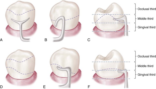
Figure 7-19 Common errors and recommended corrections in the design of bar-type clasp assemblies. A, Survey line unsuitable for the bar clasp (too high). B, Retentive portion of the bar clasp arm improperly contoured to resist dislodging force in the occlusal direction. C, Retentive tip not located in the gingival third of the abutment. D, Contour of abutment correctly altered to receive bar clasp. E and F, Correct position of bar clasp assembly.
The bar clasp arm is not a particularly flexible clasp arm because of the effects of its half-round form and its several planes of origin. Although the cast circumferential clasp arm can be made more flexible than the bar clasp arm, the combination clasp is preferred for use on terminal abutments when torque and tipping are possible, because of engagement of an undercut away from the distal extension base. Situations often exist, however, in which a bar clasp arm may be used to advantage without jeopardizing a terminal abutment. A bar clasp arm swinging distally into the undercut may be a logical choice, because movement of the clasp on the abutment as the distal extension base moves tissue-ward is minimized by the distal location of the clasp terminal.
Some advantages attributed to the infrabulge clasp are (1) its interproximal location, which may be used to esthetic advantage; (2) increased retention without tipping action on the abutment; and (3) less chance of accidental distortion resulting from its proximity to the denture border. The wearer should be meticulous in the care of a denture so made, not only for reasons of oral hygiene but also to prevent cariogenic debris from being held against tooth surfaces.
The T and Y clasp arms are the most frequently misused. It is unlikely that the full area of a T or Y terminal is ever necessary for adequate clasp retention. Although the larger area of contact would provide greater frictional resistance, this is not true clasp retention, and only that portion engaging an undercut area should be considered retentive. Only one terminal of such a clasp arm should be placed in an undercut area (Figure 7-20). The remainder of the clasp arm may be superfluous unless it is needed as part of the clasp assembly to encircle the abutment tooth by more than 180 degrees at its greatest circumference. If the bar clasp arm is made to be flexible for retentive purposes, any portion of the clasp above the height of contour will provide only limited stabilization, because it is also part of the flexible arm. Therefore in many instances, this suprabulge portion of a T or Y clasp arm may be removed, and the retentive terminal of the bar clasp should be designed to be biologically and mechanically sound rather than to conform to any alphabetical configuration.
Combination Clasp
Another strategy that may be used to reduce the effect of the Class I lever in distal extension situations includes a flexible component in the “resistance arm”; this strategy is employed in the combination clasp. The combination clasp consists of a wrought-wire retentive clasp arm and a cast reciprocal clasp arm (Figure 7-21). Although the latter may be seen in the form of a bar clasp arm, it is usually a circumferential arm. The retentive arm is almost always circumferential, but it also may be used in the manner of a bar, originating gingivally from the denture base.
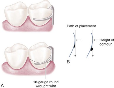
Figure 7-21 A, A combination clasp consists of a cast reciprocal arm and a tapered, round wrought-wire retentive clasp arm. The latter is cast to, or soldered to, a cast framework. This design is recommended for the anterior abutment of the posterior modification space in a Class II partially edentulous arch, where only a mesiobuccal undercut exists, to minimize the effects of a first-class lever system. B, In addition to the advantages of flexibility, adjustability, and appearance, a wrought-wire retentive arm makes only line contact with the abutment tooth, rather than broader contact with the cast clasp.
Advantages of the combination clasp include its flexibility and adjustability and the appearance of the wrought-wire retentive arm. It is used when maximum flexibility is desirable, such as on an abutment tooth adjacent to a distal extension base or on a weak abutment when a bar-type direct retainer is contraindicated. It may be used for its adjustability when precise retentive requirements are unpredictable and later adjustment to increase or decrease retention may be necessary. A third justification for its use is its esthetic advantage over cast clasps. Wrought in structure, it may be used in smaller diameters than a cast clasp, with less danger of fracture. Because it is round, light is reflected in such a manner that the display of metal is less noticeable than with the broader surfaces of a cast clasp.
The most common use of the combination clasp is on an abutment tooth adjacent to a distal extension base where only a mesial undercut exists on the abutment or where a large tissue undercut contraindicates a bar-type retainer (Figure 7-22). When a distal undercut exists that may be approached with a properly designed bar clasp arm or with a ring clasp (despite its several disadvantages), a cast clasp can be located so that it will not cause abutment tipping as the distal extension base moves tissue-ward. When the undercut is on the side of the abutment away from the extension base, the tapered wrought-wire retentive arm offers greater flexibility than does the cast clasp arm and therefore better dissipates functional stresses. For this reason, the combination clasp is preferred (see Figure 7-22, D).
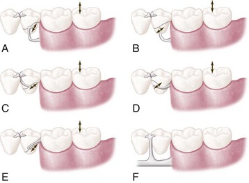
Figure 7-22 Five types of extracoronal direct retainer assemblies that may be used on abutments adjacent to the distal extension base to avoid or minimize the effects of the cantilever design. Arrows indicate the general direction of movement of retentive tips of retainer arms when the denture base rotates toward and away from the edentulous ridge. A, Distobuccal undercut engaged by one-half T-type bar clasp. The portion of the clasp arm on and above the height of contour might afford some stabilization against horizontal rotation of the denture base. B, I-bar placed in undercut at the middle (anteroposteriorly) of the buccal surface. This retainer contacts the tooth only at its tip. Note that the guiding plane on the distal aspect of the abutment is contacted by the metal of the denture framework, and that a mesial rest is used. C, Interproximal ring clasp engaging the distobuccal undercut. Bar-type retainer cannot be used because of tissue undercuts inferior to the buccal surface of the abutment. D, Round, uniformly tapered 18-gauge wrought-wire circumferential retainer arm engaging the mesiobuccal undercut. A wrought-wire arm, instead of a cast arm, should be used in this situation because of the ability of wrought wire to flex omnidirectionally. A cast half-round retainer arm would not flex edgewise, which could result in excessive stress on the tooth when rotation of the denture base occurs. E, A hairpin clasp may be used when the undercut lies cervical to the origin of the retainer arm. Both hairpin and interproximal ring clasps may be used to engage the distobuccal undercut on the terminal abutment of the distal extension denture. However, the distobuccal undercut on the terminal abutment should be engaged by a bar-type clasp in the absence of a large buccal tissue undercut cervical to the terminal abutment. Hairpin and interproximal ring clasps are the least desirable of the clasping situations illustrated here. F, Lingual view shows the use of double occlusal rests, connected to the lingual bar by the minor connector in illustrated designs. This design eliminates the need for a lingual clasp arm, places the fulcrum line anteriorly to make better use of the residual ridge for support, and provides stabilization against horizontal rotation of the denture base.
The combination clasp has several disadvantages: (1) it involves extra steps in fabrication, particularly when high-fusing chromium alloys are used; (2) it may be distorted by careless handling on the part of the patient; (3) because it is bent by hand, it may be less accurately adapted to the tooth and therefore may provide less stabilization in the suprabulge portion; and (4) it may distort with function and not engage the tooth. The disadvantages of the wrought-wire clasp are offset by its several advantages, which include (1) its flexibility; (2) its adjustability; (3) its esthetic advantage over other retentive circumferential clasp arms; (4) coverage of a minimum of tooth surface as a result of its line contact with the tooth, rather than having the surface contact a cast clasp arm; and (5) a less likely occurrence of fatigue failure in service with the tapered wrought-wire retentive arm versus the cast, half-round retentive arm.
The disadvantages listed previously should not prevent its use regardless of the type of alloy that is used for the cast framework. Technical problems are minimized by selecting the best wrought wire for this purpose, then casting to it or soldering it to the cast framework. Selection of wrought wire, attachment of it to the framework, and subsequent laboratory procedures to maintain its optimum physical properties are presented in Chapter 12.
The patient may be taught to avoid distortion of the wrought wire by the explanation that to remove a partial denture, the fingernail should always be applied to its point of origin, where it is held rigid by the casting, rather than to the flexible terminal end. Often, lingual retention may be used rather than buccal retention, especially on a mandibular abutment, so that the patient never touches the wrought-wire arm during removal of the denture. Instead, removal may be accomplished by lifting against the cast reciprocal arm located on the buccal side of the tooth. This may negate the esthetic advantage of the wrought-wire clasp arm, and esthetics should be given preference when the choice must be made between buccal and lingual retention. In most situations, however, retention must be used where it is possible, and the clasp designed accordingly.
Clasps Designed Without Movement Accommodation
Circumferential Clasp
Although a thorough knowledge of the principles of clasp design should lead to a logical application of those principles, it is better when some of the more common clasp designs are considered individually. The circumferential clasp will be considered first as an all-cast clasp.
The circumferential clasp is usually the most logical clasp to use with all tooth-supported partial dentures because of its retentive and stabilizing ability (Figure 7-23). Only when the retentive undercut may be approached better with a bar clasp arm or when esthetics will be enhanced should the latter be used. The circumferential clasp arm has the following disadvantages:
Figure 7-23 Cast circumferential retentive clasp arms properly designed. They originate on or occlusal to the height of contour, which they then cross in their terminal third, and engage retentive undercuts progressively as their taper decreases and their flexibility increases.
Despite its disadvantages, the cast circumferential clasp arm may be used effectively, and many of these disadvantages may be minimized by mouth preparation. Adequate mouth preparation will permit its point of origin to be placed far enough below the occlusal surface to avoid poor esthetics and increased tooth dimension (see Figure 7-23). Although some of the disadvantages listed imply that the bar-type clasp may be preferable, the circumferential clasp is actually superior to a bar clasp arm that is improperly used or poorly designed.
Experience has shown that faulty application and design too often negate the possible advantages of the bar clasp arm, whereas the circumferential clasp arm is not as easily misused.
The basic form of the circumferential clasp is a buccal and lingual arm originating from a common body (Figure 7-24). This clasp is used improperly when two retentive clasp arms originate from the body and occlusal rest areas and approach bilateral retentive areas on the side of the tooth away from the point of origin. The correct form of this clasp has only one retentive clasp arm, opposed by a nonretentive reciprocal arm on the opposite side. A common error is to use this clasp improperly by making both clasp terminals retentive. This not only is unnecessary but also disregards the need for reciprocation and bilateral stabilization. Other common errors in the design of circumferential clasps are illustrated in Figure 7-25.
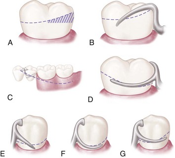
Figure 7-25 Some improper applications of circumferential clasp design and their recommended corrections. A, Tooth with undesirable height of contour in its occlusal third. B, Unsuitable contour and location of retentive clasp arm on an unmodified abutment. C, More favorable height of contour achieved by modification of the abutment. D, Retentive clasp arm properly designed and located on a modified abutment. E, Unsuitable contour and location of the retentive arm in relation to the height of contour (straight arm configuration provides poor approach to the retentive area and is less resistant to dislodging force). F, Terminal portion of the retentive clasp arm located too close to the gingival margin. G, Clasp arm that is properly designed and located.
Ring Clasp
The circumferential type of clasp may be used in several forms. It appears as though many of these forms of the basic circumferential clasp design were developed to accommodate situations in which corrected tooth modifications could not be or were not accomplished by the dentist. One is the ring clasp, which encircles nearly all of a tooth from its point of origin (Figure 7-26). It is used when a proximal undercut cannot be approached by other means. For example, when a mesiolingual undercut on a lower molar abutment cannot be approached directly because of its proximity to the occlusal rest area and cannot be approached with a bar clasp arm because of lingual inclination of the tooth, the ring clasp encircling the tooth allows the undercut to be approached from the distal aspect of the tooth.
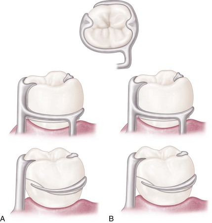
Figure 7-26 Ring clasp(s) encircling nearly all of the tooth from its point of origin. A, Clasp originates on the mesiobuccal surface and encircles the tooth to engage the mesiolingual undercut. B, Clasp originates on the mesiolingual surface and encircles the tooth to engage the mesiobuccal undercut. In either example, a supporting strut is used on the nonretentive side (drawn both as direct view of near side of tooth and as mirror view of opposite side).
The clasp should never be used as an unsupported ring (Figure 7-27) because if it is free to open and close as a ring, it cannot provide reciprocation or stabilization. Instead the ring-type clasp should always be used with a supporting strut on the nonretentive side, with or without an auxiliary occlusal rest on the opposite marginal ridge. The advantage of an auxiliary rest is that further movement of a mesially inclined tooth is prevented by the presence of a distal rest. In any event, the supporting strut should be regarded as a minor connector from which the flexible retentive arm originates. Reciprocation then comes from the rigid portion of the clasp lying between the supporting strut and the principal occlusal rest.
Figure 7-27 Improperly designed ring clasp lacking necessary support. Such a clasp lacks any reciprocating or stabilizing action because the entire circumference of the clasp is free to open and close. A supporting strut should always be added on the nonretentive side of the abutment tooth, which then becomes, in effect, a minor connector from which a tapered and flexible retentive clasp arm originates.
The ring-type clasp should be used on protected abutments, whenever possible, because it covers such a large area of tooth surface. Esthetics need not be considered on such a posteriorly located tooth.
A ring-type clasp may be used in reverse on an abutment located anterior to a tooth-bounded edentulous space (Figure 7-28). Although potentially an effective clasp, this clasp covers an excessive amount of tooth surface and can be esthetically objectionable. The only justification for its use is when a distobuccal or distolingual undercut cannot be approached directly from the occlusal rest area and/or tissue undercuts prevent its approach from a gingival direction with a bar clasp arm.
Embrasure Clasp
In the fabrication of an unmodified Class II or Class III partial denture, no edentulous spaces are available on the opposite side of the arch to aid in clasping. Mechanically, this is a disadvantage. However, when the teeth are sound and retentive areas are available, or when multiple restorations are justified, clasping can be accomplished by means of an embrasure clasp (Figure 7-29).
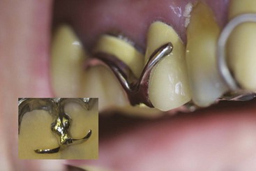
Figure 7-29 Embrasure clasps extend through occlusal embrasures to engage facial undercuts when no modification spaces are present.
Sufficient space must be provided between the abutment teeth in their occlusal third to make room for the common body of the embrasure clasp (Figure 7-30), yet the contact area should not be eliminated entirely. Historically, this clasp assembly demonstrates a high percentage of fracture caused by inadequate tooth preparation in the contact area. Because vulnerable areas of the teeth are involved, abutment protection with inlays or crowns is recommended. The decision to use unprotected abutments must be made at the time of oral examination and should be based on the patient’s age, caries index, and oral hygiene, as well as on whether existing tooth contours are favorable or can be made favorable by tooth modification. Preparation of adjacent, contacting, uncrowned abutments to receive any type of embrasure clasp of adequate interproximal bulk is difficult, especially when it is opposed by natural teeth.
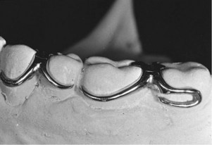
Figure 7-30 Embrasure and hairpin circumferential retentive clasp arms. The terminus of each engages a suitable retentive undercut. Use of a hairpin-type clasp on the second molar is made necessary by the fact that the only available undercut lies directly below the point of origin of the clasp arm.
The embrasure clasp always should be used with double occlusal rests, even when definite proximal shoulders can be established (Figure 7-31). This is done to avoid interproximal wedging by the prosthesis, which could cause separation of the abutment teeth, resulting in food impaction and clasp displacement. In addition to providing support, occlusal rests serve to shunt food away from contact areas. For this reason, occlusal rests should always be used whenever food impaction is possible.
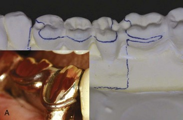
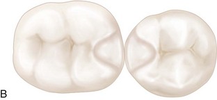
Figure 7-31 A, Example of the use of an embrasure clasp for a Class II partially edentulous arch. Embrasure clasp on the two left molar abutments was used in the absence of posterior modification space. B, Occlusal and proximal surfaces of adjacent molar and premolar prepared for embrasure clasp. Note that rest seat preparations are extended both buccally and lingually to accommodate the retentive and reciprocal clasp arms. Adequate preparation confined to the enamel can rarely be accomplished for such a clasp, especially when clasped teeth are opposed by natural teeth.
Embrasure clasps should have two retentive clasp arms and two reciprocal clasp arms that are bilaterally or diagonally opposed. An auxiliary occlusal rest or a bar clasp arm can be substituted for a circumferential reciprocal arm, as long as definite reciprocation and stabilization result. A lingually placed retentive bar clasp arm may be substituted if a rigid circumferential clasp arm is placed on the buccal surface for reciprocation, provided lingual retention is used on the opposite side of the arch. Other less commonly used modifications of the cast circumferential clasp that are of historical interest are the multiple clasp, the half-and-half clasp, and the reverse-action clasp.
Back-action Clasp
The back-action clasp is a modification of the ring clasp; it has all of the same disadvantages and no apparent advantages (Figure 7-32). Its use is difficult to justify. The undercut can usually be approached just as well by using a conventional circumferential clasp, with less tooth coverage and less display of metal. With the circumferential clasp, the proximal tooth surface can be used as a guiding plane, as it should be, and the occlusal rest can have the rigid support it requires. An occlusal rest always should be attached to some rigid minor connector and should never be supported by a clasp arm alone. If the occlusal rest is part of a flexible assembly, it cannot function adequately as an occlusal rest.
Multiple Clasp
The multiple clasp simply consists of two opposing circumferential clasps joined at the terminal end of the two reciprocal arms (Figure 7-33). It is used when additional retention and stabilization are needed, usually on tooth-supported partial dentures. It may be used for multiple clasping in instances in which the partial denture replaces an entire half of the dental arch. It may be used rather than an embrasure clasp when the only available retentive areas are adjacent to each other. Its disadvantage is that two embrasure approaches are necessary rather than a single common embrasure for both clasps.
Half-and-half Clasp
The half-and-half clasp consists of a circumferential retentive arm arising from one direction and a reciprocal arm arising from another (Figure 7-34). The second arm must arise from a second minor connector, and this arm is used with or without an auxiliary occlusal rest. Reciprocation arising from a second minor connector usually can be accomplished with a short bar or with an auxiliary occlusal rest, thereby avoiding so much tooth coverage. There is little justification for the use of the half-and-half clasp in bilateral extension base partial dentures. Its design was originally intended to provide dual retention, a principle that should be applied only to unilateral partial denture design.
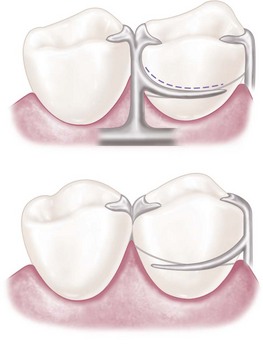
Figure 7-34 Half-and-half clasp consists of one circumferential retentive arm arising from the distal aspect and a second circumferential arm arising from the mesial aspect on the opposite side, with or without a secondary occlusal rest. Broken line illustrates a nonretentive reciprocal clasp arm used without a secondary occlusal rest (mirror view).
Reverse-action Clasp
The reverse-action, or hairpin, clasp arm is designed to allow a proximal undercut to be engaged from an occlusal approach (Figure 7-35). Other methods of accomplishing the same result involve use of a ring clasp originating on the opposite side of the tooth or a bar clasp arm originating from a gingival direction. However, when a proximal undercut must be used on a posterior abutment, and when tissue undercuts, tilted teeth, or high tissue attachments prevent the use of a bar clasp arm, the reverse-action clasp may be used successfully. Although the ring clasp may be preferable, lingual undercuts may prevent the placement of a supporting strut without tongue interference. In this limited situation, the hairpin clasp arm serves adequately, despite its several disadvantages. The clasp covers considerable tooth surface and may trap debris; its occlusal origin may increase the functional load on the tooth, and its flexibility is limited. Esthetics usually need not be considered when the clasp is used on a posterior abutment, but the hairpin clasp arm does have the additional disadvantage of displaying too much metal for use on an anterior abutment.
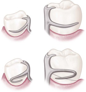
Figure 7-35 A reverse-action, or hairpin, clasp arm may be used on abutments of tooth-supported dentures when the proximal undercut lies below the point of origin of the clasp (mirror view). It may be esthetically objectionable and covers considerable tooth surface. It should be used only when a bar-type retentive arm is contraindicated because of a tissue undercut, a tilted tooth, or a shallow vestibule.
When properly designed, the reverse-action clasp should make a hairpin turn to engage an undercut below the point of origin (see Figure 7-35). The upper part of the arm of this clasp should be considered a minor connector, giving rise to the tapered lower part of the arm. Therefore only the lower part of the arm should be flexible. With the retentive portion beginning beyond the turn, only the lower part of the arm should flex over the height of contour to engage a retentive undercut. The bend that connects the upper and lower parts of the arm should be rounded to prevent stress accumulation and fracture of the arm at the bend. The clasp should be designed and fabricated with this in mind.
These are the various types of cast circumferential clasps. As was mentioned previously, they may be used in combination with bar clasp arms as long as differentiation is made between retention and reciprocation by their form and location. Circumferential and bar clasp arms may be made flexible (retentive) or rigid (reciprocal) in any combination, as long as each retentive clasp arm is opposed by a rigid reciprocal component.
Use of many of the less desirable clasp forms can be avoided by changing the crown forms of the abutments through tooth modification within the enamel or with restorations. When abutment coverage is fabricated, tooth contours should be established that will permit the use of the most desirable clasp forms, rather than a form that makes it necessary to use a less desirable clasp design. This is best accomplished by first altering the crown contour of abutment teeth not designated for restoration to meet the requirements of guiding planes and survey line location. This is followed by the prescribed crown preparations. Before tooth reduction is performed for the prescribed crown preparations, the requirements of guiding planes and survey line location should be met.
Analysis of Tooth Contours for Retentive Clasps
Although the extracoronal, or clasp-type, direct retainer is used more often than the internal attachment, it is commonly misused. It is hoped that a better understanding of the principles of clasp design will lead to more intelligent use of this retainer. To best gain this understanding, it is vitally important for the clinician to consider how tooth contour and removable partial denture components must interact (be related) to allow stable prosthetic function. Just as unaltered natural teeth are not appropriately contoured to receive fixed partial dentures without preparation, the teeth that are engaged by a removable partial denture must be contoured to support, stabilize, and retain the functioning prosthesis. Analysis and accomplishment of tooth modification when it is required for optimum stability and retention are necessary for the success of the prosthesis.
Critical areas of an abutment that provide for retention and stabilization (reciprocation) can be identified only with the use of a dental cast surveyor (Table 7-1). To enhance the understanding of direct retainers, an introduction of the dental cast surveyor is appropriate at this time. Surveying will be covered in detail in Chapter 11.
Table 7-1 Function and Position of Clasp Assembly Parts
| Component Part | Function | Location |
|---|---|---|
| Rest | Support | Occlusal, lingual, incisal |
| Minor connector | Stabilization | Proximal surfaces extending from a prepared marginal ridge to the junction of the middle and gingival one third of the abutment crown |
| Clasp arms | Stabilization (reciprocation) | Middle one third of crown |
| Retention | Gingival one third of crown in measured undercut |
The cast surveyor (Figure 7-36) is a simple instrument that is essential for planning partial denture treatment. Its main working parts are the vertical arm and the adjustable table, which hold the cast in a fixed relation to the vertical arm. This relationship of the vertical arm to the cast represents the path of placement that the partial denture will ultimately take when inserted or removed from the mouth (Figure 7-37).
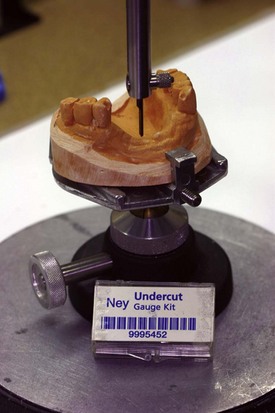
Figure 7-36 Essential parts of a dental surveyor (Ney Parallelometer, Dentsply Ceramco, Burlington, NJ), showing the vertical spindle in relation to an adjustable table.
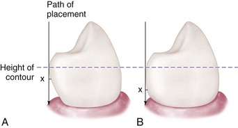
Figure 7-37 Angle of cervical convergence on two teeth presenting dissimilar contours. A greater angle of cervical convergence on tooth A necessitates placement of a clasp terminus, X, nearer the height of contour than when a lesser angle exists, as in B. It is apparent that uniform clasp retention depends on depth (amount) of the tooth undercut rather than on distance below the height of the contour at which the clasp terminus is placed.
The adjustable table may be tilted in relation to the vertical arm of the surveyor until a path can be found that best satisfies all involved factors (Figure 7-38). A cast in a horizontal relationship to the vertical arm represents a vertical path of placement; a cast in a tilted relationship represents a path of placement toward the side of the cast that is on an upward slant. The vertical arm, when brought in contact with a tooth surface, identifies the location on the clinical crown where the greatest convexity exists. This line, called the height of contour (specific to the surveyor-defined path), is the boundary between (1) an occlusal or incisal region of the tooth that is freely accessible to a prosthesis and (2) a gingival region of the tooth that can be accessed only when a portion of the prosthesis elastically deforms and recovers to contact the tooth. This surveyor-defined path and the subsequent tooth height of contour will indicate the areas available for retention and those available for support and stabilization, as well as the existence of tooth and other tissue interference with the path of placement.
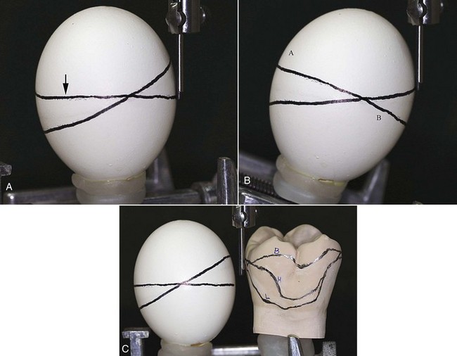
Figure 7-38 Relationship of height of contour, suprabulge, and infrabulge. A, When an egg is placed with its long axis parallel to the surveying tool, the height of contour is found at its greatest circumference, here designated by the arrow. In this example, the second line is diagonal to the line outlining the height of contour and is either above the height of contour (right side of egg), referred to as the suprabulge region, or below the height of contour (left side of egg), referred to as the infrabulge region. B, If the long axis of the egg is reoriented so that the previous diagonal line is now at the greatest circumference, the original “height of contour line” no longer is at the greatest circumference. The line segment at A is in the suprabulge region, and the line segment B is in the infrabulge region. Changing the orientation alters the relationship of surfaces relative to the greatest circumference and consequently alters suprabulge and infrabulge locations. C, Just as the height of contour changes as orientation changes for the egg, when a tooth orientation changes, the height of contour is altered. For this molar, the line H was produced with a horizontal orientation. When the tooth was inclined buccally, the height of contour moved to B, relative to the horizontal location. Alternatively, when the tooth was inclined lingually, the height of contour moves to L, relative to the horizontal location.
When the surveyor blade contacts a tooth on the cast at its greatest convexity, a triangle is formed. The apex of the triangle is at the point of contact of the surveyor blade with the tooth, and the base is the area of the cast representing the gingival tissue (see Figure 11-18). The apical angle is called the angle of cervical convergence (see Figure 7-37). This angle may be measured as described in Chapter 11, or it may be estimated by observing the triangle of light visible between the tooth and the surveyor blade. For this reason, a wide surveyor blade rather than a small cylindrical tool is used so it is easier to see the triangle of light. The importance of this angle lies in its relationship to the amount of retention.
Amount of Retention
Clasp retention is based on resistance to deformation of the metal. For a clasp to be retentive, it must be placed in an undercut area of the tooth, where it is forced to deform upon application of a vertical dislodging force (Figure 7-39). It is this resistance to deformation along an appropriately selected path that generates retention (Figure 7-40). Such resistance to deformation is dependent on several factors and is also proportionate to the flexibility of the clasp arm.
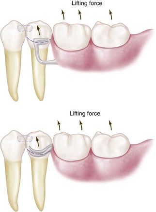
Figure 7-39 Retention is provided primarily by the flexible portion of the clasp assembly. Retentive terminals are ideally located in measured undercuts in the gingival third of abutment crowns. When force acts to dislodge the restoration in an occlusal direction, the retentive arm is forced to deform as it passes from the undercut location over the height of contour. The amount of retention provided by the clasp arm is determined by its length, diameter, taper, cross-sectional form, contour, type of alloy, and location and depth of undercut engaged.
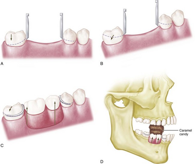
Figure 7-40 A, Retentive areas are not sufficient to resist reasonable dislodging forces when a cast is surveyed at its most advantageous position (occlusal plane parallel to the surveyor table), even though guide planes could be established with minor tooth modification. B, Tilting cast creates functionally ineffective tooth contours, which are present only in relation to the surveying rod and do not exist when compared with the most advantageous position (position in which restoration will be subject to dislodging forces in an occlusal direction). C-D, Clasps designed at tilt are ineffective without the development of corresponding guide planes to resist displacement when the restoration is subject to dislodging forces in the occlusal direction.
The interaction of a number of factors under the control of the clinician combines to produce retention. These include both tooth (planned and executed by the clinician) and prosthesis (to be planned by the dentist and executed by the laboratory technician) factors.
Tooth factors include the size of the angle of cervical convergence (depth of undercut) and how far the clasp terminal is placed into the angle of cervical convergence. Prosthesis factors include the flexibility of the clasp arm. Clasp flexibility is the product of clasp length (measured from its point of origin to its terminal end), clasp relative diameter (regardless of its cross-sectional form), clasp cross-sectional form or shape (whether it is round, half-round, or some other form), and the material used in making the clasp. The retention characteristics of gold alloy, chrome alloy, titanium, or titanium alloy depend on whether it is in cast or wrought form.
Size of and Distance Into the Angle of Cervical Convergence
To be retentive, a tooth must have an angle of convergence cervical to the height of contour. When it is surveyed, any single tooth will have a height of contour or an area of greatest convexity. Areas of cervical convergence may not exist when the tooth is viewed in relation to a given path of placement. Also, certain areas of cervical convergence may not be usable for the placement of retentive clasps because of their proximity to gingival tissue.
This is best illustrated by mounting a spherical object, such as an egg, on the adjustable table of a dental surveyor (see Figure 7-38). The egg now represents the cast of a dental arch or, more correctly, one tooth of a dental arch. The egg first is placed perpendicular to the base of the surveyor and is surveyed so the height of contour can be determined. The vertical arm of the surveyor represents the path of placement that a denture would take, and conversely its path of removal.
With a carbon marker, a circumferential line has been drawn on an egg at its greatest circumference, as shown by the arrow in Figure 7-38, A. This line, which Kennedy called the height of contour, is its greatest convexity. Cummer spoke of it as the guideline because it is used as a guide in the placement of retentive and nonretentive clasps. To this, DeVan added the terms suprabulge, denoting the surfaces sloping superiorly, and infrabulge, denoting the surfaces sloping inferiorly.
Any areas cervical to the height of contour may be used for the placement of retentive clasp components, whereas areas occlusal to the height of contour may be used for the placement of nonretentive, stabilizing, or reciprocating components. Obviously, only flexible components may be placed gingivally to the height of contour because rigid elements would not flex over the height of contour or contact the tooth in the undercut area.
With the original height of contour marked on the egg, the egg is now tilted from the perpendicular to an angular relation with the base of the surveyor (see Figure 7-38, B). Its relation to the vertical arm of the surveyor has now been changed, just as a change in the position of a dental cast would bring about a different relationship with the surveyor. The vertical arm of the surveyor still represents the path of placement. However, its relation to the egg is totally different.
Again, the carbon marker is used to delineate the height of contour or the greatest convexity. It will be seen that areas that were formerly infrabulge are now suprabulge, and vice versa. A retentive clasp arm placed below the height of contour in the original position may now be excessively retentive or totally nonretentive, whereas a nonretentive stabilizing or reciprocal arm that is located above the height of contour in the first position may now be located in an area of undercut. Figure 7-35 C illustrates this principle compared with a tooth example showing that changes in tilt can significantly alter heights of contour.
The location and depth of a tooth undercut available for retention are therefore relative only to the path of placement and removal of the partial denture. At the same time, nonretentive areas on which rigid components of the clasp may be placed exist only for a given path of placement (see Figure 7-39).
If conditions are found that are not favorable for the particular path of placement under consideration, a study should be conducted for a different path of placement. The cast is merely tilted in relation to the vertical arm until the most suitable path is found. The most suitable path of placement is generally considered to be the path of placement that will require the least amount of mouth preparation necessary to place the components of the partial denture in their ideal position on the tooth surfaces and in relation to the soft tissue. Then mouth preparations are planned with a definite path of placement in mind.
It is important to remember that tooth surfaces can be recontoured through selective grinding or the placement of restorations (mouth preparations) to achieve a more suitable path of placement. The path of placement also must take into consideration the presence of tissue undercuts that would interfere with the placement of major connectors, the location of vertical minor connectors, the origin of bar clasp arms, and the denture bases.
When the theory of clasp retention is applied to the abutment teeth in a dental arch during surveying of the dental cast, each tooth may be considered individually and in relation to the other abutment teeth as far as the designs of retentive and stabilizing (reciprocating) components are concerned. This is necessary because the relationship of each tooth to the entire arch and to the design of the whole prosthesis has been considered previously when teeth were selected or modified to achieve the most suitable path of placement. Once this relationship of the cast to the surveyor has been established, the height of contour on each abutment tooth becomes fixed, and the clasp design for each must be considered separately.
A positive path of placement and removal is made possible by the contact of rigid parts of the denture framework with parallel tooth surfaces, which act as guiding planes. Because guiding planes control the path of placement and removal, they can provide additional retention for the partial denture by limiting the possibilities that exist for its dislodgment. The more vertical are the walls (guiding planes) that are prepared parallel to the path of insertion, the fewer the possibilities that exist for dislodgment. If some degree of parallelism does not exist during placement and removal, trauma to the teeth and supporting structures and strain on the denture parts are inevitable. This ultimately results in damage to the teeth and their periodontal support or to the denture itself, or both. Therefore without guiding planes, clasp retention will be detrimental or practically nonexistent. If clasp retention is frictional only because of an active relationship of the clasp to the teeth, then orthodontic movement or damage to periodontal tissue, or both, will result. Instead a clasp should bear a passive relationship to the teeth, except when a dislodging force is applied. In addition to the degree of the angle of cervical convergence and the distance a clasp is placed into the angle of cervical convergence, the amount of retention generated by a clasp depends on its flexibility. This is a function of clasp length, diameter, taper, cross-sectional form, and material.
The amount of retention also depends on the flexibility of a clasp arm. This is a function of clasp length, diameter, cross-sectional form, and material.
Length of Clasp Arm
The longer the clasp arm is, the more flexible it will be, all other factors being equal. The length of a circumferential clasp arm is measured from the point at which a uniform taper begins. Tooth modification providing increased length to a suprabulge retentive clasp by allowing the retentive tip to approach the undercut from a gingival direction optimizes clasp retention (see Figure 7-8). The retentive circumferential clasp arm should be tapered uniformly from its point of origin through the full length of the clasp arm (Figure 7-41).
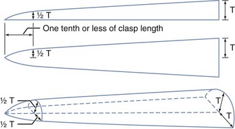
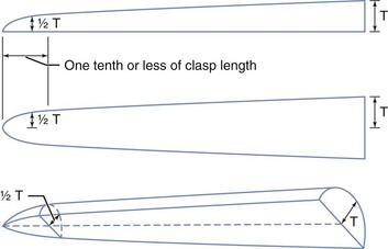
Figure 7-41 The retentive cast clasp arm should be tapered uniformly from its point of attachment at the clasp body to its tip. Dimensions at the tip are about half those at the point of attachment. The clasp arm so tapered is approximately twice as flexible as one without any taper. T, Clasp thickness.
(Courtesy The Argen Corporation, New York, NY.)
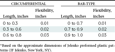
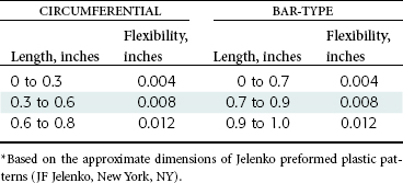
The length of a bar clasp arm also is measured from the point at which a uniform taper begins. Generally the taper of a bar clasp arm should begin at its point of origin from a metal base, or at the point at which it emerges from a resin base (Figure 7-42). Although a bar clasp arm usually will be longer than a circumferential clasp arm, its flexibility will be less because its half-round form lies in several planes; this prevents its flexibility from being proportionate to its total length. Tables 7-2 and 7-3 give an approximate depth of undercut that may be used for the cast gold and chromium-cobalt retentive clasp arms of circumferential and bar-type clasps. Based on a proportional limit of 60,000 psi and on the assumption that the clasp arm is properly tapered, the clasp arm should be able to flex repeatedly within the limits stated without hardening or rupturing because of fatigue. It has been estimated that alternate stress applications of the fatigue type are placed on a retainer arm during mastication and other force-producing functions about 300,000 times a year.
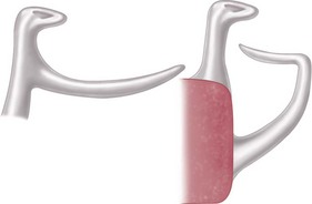
Figure 7-42 Length of the tapered cast retentive clasp arm is measured along the center portion of the arm until it joins the clasp body (circumferential) or becomes part of the denture base or is embedded in the base (bar-type clasp).
Diameter of Clasp Arm
The greater the average diameter of a clasp arm is, the less flexible it will be, all other factors being equal. If its taper is absolutely uniform, the average diameter will be at a point midway between its origin and its terminal end. If its taper is not uniform, a point of flexure—and therefore a point of weakness—will exist; this then will be the determining factor in its flexibility, regardless of the average diameter of its entire length.
Cross-sectional Form of the Clasp Arm
Flexibility may exist in any form, but it is limited to one direction in the case of the half-round form. The only universally flexible form is the round form, which is practically impossible to obtain by casting and polishing.
Because most cast clasps are essentially half-round in form, they may flex away from the tooth, but edgewise flexing (and edgewise adjustment) is limited. For this reason, cast retentive clasp arms are more acceptable in tooth-supported partial dentures in which they are called on to flex only during placement and removal of the prosthesis. A retentive clasp arm on an abutment adjacent to a distal extension base not only must flex during placement and removal but also must be capable of flexing during functional movement of the distal extension base. It must have universal flexibility to avoid transmission of tipping stresses to the abutment tooth, or it must be capable of disengaging the undercut when vertical forces directed against the denture are toward the residual ridge. A round clasp is the only circumferential clasp form that may be safely used to engage a tooth undercut on the side of an abutment tooth away from the distal extension base. The location of the undercut is perhaps the single most important factor in selection of a clasp for use with distal extension partial dentures.
Material Used for the Clasp Arm
Although all cast alloys used in partial denture construction possess flexibility, their flexibility is proportionate to their bulk. If this were not true, other components of the partial denture could not have the necessary rigidity. A disadvantage of a cast gold partial denture is that its bulk must be increased to obtain needed rigidity at the expense of added weight and increased cost. It cannot be denied that greater rigidity with less bulk is possible through the use of chromium-cobalt alloys.
Although cast gold alloys may have greater resiliency than do cast chromium-cobalt alloys, the fact remains that the structural nature of the cast clasp does not approach the flexibility and adjustable nature of the wrought-wire clasp. Because it was formed by being drawn into a wire, the wrought-wire clasp arm has toughness exceeding that of a cast clasp arm. The tensile strength of a wrought structure is at least 25% greater than that of the cast alloy from which it was made. It may therefore be used in smaller diameters to provide greater flexibility without fatigue and ultimate fracture.
Relative Uniformity of Retention
Now that the factors inherent to a determination of the amount of retention from individual clasps have been reviewed, it is important to consider the coordination of relative retention between various clasps in a single prosthesis.
The size of the angle of convergence will determine how far a given clasp arm should be placed into that angle. By disregarding—for the time being—variations in clasp flexibility, the relative uniformity of retention will depend on the location of the retentive part of the clasp arm, not in relation to the height of contour, but in relation to the angle of cervical convergence.
The retention on all principal abutments should be as equal as possible. Although esthetic placement of clasp arms is desirable, it may not be possible to place all clasp arms in the same occlusocervical relationship because of variations in tooth contours. However, retentive surfaces may be made similar by altering tooth contours or by using cast restorations with similar contours.
Retentive clasp arms must be located so that they lie in the same approximate degree of undercut on each abutment tooth. In Figure 7-37, this is seen at point X on both teeth—A and B—despite variation in the distance below the height of contour. Should both clasp arms be placed equidistant below the height of contour, the higher location on tooth B would have too little retention, whereas the lower location on tooth A would be too retentive.
Measurement of the degree of undercut by mechanical means with the use of a surveyor is important. However, undercut identification is only one factor that is important to consider when one is providing appropriate retention for a removable partial denture.
Stabilizing-Reciprocal Cast Clasp Arm
When the direct retainer comes into contact with the tooth, the framework must be stabilized against horizontal movement for the required clasp deformation to occur. This stabilization is derived from cross-arch framework contacts or from a stabilizing or reciprocal clasp in the same clasp assembly. To provide true reciprocation, the reciprocal clasp must be in contact during the entire period of retentive clasp deformation. This is best provided with lingual-palatal, guide-plane surfaces.
A stabilizing (reciprocal) clasp arm should be rigid. Therefore it is shaped somewhat differently than is the cast retentive clasp arm, which must be flexible. Its average diameter must be greater than the average diameter of the opposing retentive arm, to increase desired rigidity. A cast retentive arm is tapered in two dimensions, as illustrated in Figure 7-41, whereas a reciprocal arm should be tapered in one dimension only, as shown in Figure 7-43. Achieving such a form for the arm requires freehand waxing of patterns.
Implants as Direct Retainers
As was stated earlier, in situations where support requirements are adequately met by available oral tissues, dental implants can be used for retention and provide the advantage of eliminating a visible clasp. The unique aspect of implant use with removable partial dentures (RPDs) is that their location generally can be prescribed, meaning that the clinician selects the best location. The location within the modification space must first consider anatomic characteristics of bone availability. It would not be a great advantage to a patient if extensive augmentation procedures were required to allow implant placement in conjunction with an RPD.
If anatomic needs are met, placement of an implant within a modification space to the advantage of retentive needs requires consideration of anterior, mid, or distal placement. Because retainers utilizing teeth have always been restricted to tooth locations at either end of a span, the mid-span location typically is not considered. However, the application of implants allows consideration of where the most beneficial location of retention can be provided, which forces consideration of where the most efficient resistance to movement away from the denture base can be provided. Placement at either extreme of the denture base may allow greater movement than placement at a mid-point, and should be taken into consideration.
Other Types of Retainers
Lingual Retention in Conjunction With Internal Rests
The internal rest is covered in Chapter 6. It is emphasized that the internal rest is not used as a retainer, but that its near-vertical walls provide for reciprocation against a lingually placed retentive clasp arm. For this reason, visible clasp arms may be eliminated, thus avoiding one of the principal objections to the extracoronal retainer.
Such a retentive clasp arm, terminating in an existing or prepared infrabulge area on the abutment tooth, may be of any acceptable design. It is usually a circumferential arm arising from the body of the denture framework at the rest area. It should be wrought because the advantages of adjustability and flexibility make the wrought clasp arm preferable. It may be cast with gold or a low-fusing, chromium-cobalt alloy, or it may be assembled by being soldered to one of the higher-fusing, chromium-cobalt alloys. In any event, future adjustment or repair is facilitated.
The use of lingual extracoronal retention avoids much of the cost of the internal attachment, yet disposes of a visible clasp arm when esthetics must be considered. Often it is employed with a tooth-supported partial denture only on the anterior abutments, and when esthetics is not a consideration, the posterior abutments are clasped in the conventional manner.
One of the dentist’s prime considerations in clasp selection is the control of stress transferred to the abutment teeth when the patient exerts an occluding force on the artificial teeth. The location and design of rests, the clasp arms, and the position of minor connectors as they relate to guiding planes are key factors in controlling transfer of stress to abutments. Errors in the design of a clasp assembly can result in uncontrolled stress to abutment teeth and their supporting tissues. Some common errors and their corrections are illustrated in Figures 7-44 and 7-45.
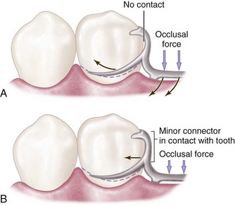
Figure 7-44 A, Minor connector supporting the distal rest does not contact the prepared guiding plane, resulting in uncontrolled stress to the abutment tooth. B, A minor connector contacts the prepared guiding plane and directs stresses around the arch through the proximal contacts.
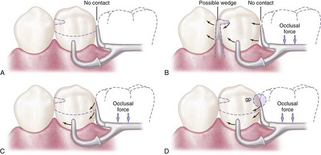
Figure 7-45 A, Clasp assembly designed so that the vertical occlusal force results in movement of the proximal plate cervically and out of contact with the guiding plane, as illustrated in (B). This lack of contact may contribute to a possible wedging effect. C, Extending contact of the proximal plate on the prepared guiding plane or, as in (D), eliminating space between the artificial tooth and the guiding plane (gp) will help direct stresses around the arch through proximal contacts.
The choice of clasp design should be based on biological and mechanical principles. The dentist responsible for the treatment being rendered must be able to justify the clasp design used for each abutment tooth in keeping with these principles.
Internal Attachments
As was mentioned earlier in the chapter, the principle of the internal attachment was first formulated by Dr. Herman E.S. Chayes in 1906. One such attachment manufactured commercially still carries his name. Although it may be fabricated by the dental technician as a cast dovetail fitting into a counterpart receptacle in the abutment crown, the alloys used in manufactured attachments and the precision with which they are constructed make the ready-made attachment preferable to any of this type that can be fabricated in the dental laboratory. Much credit is due the manufacturers of metals used in dentistry for continued improvements in the design of internal attachments.
The internal attachment has two major advantages over the extracoronal attachment: elimination of visible retentive and support components, and better vertical support through a rest seat located more favorably in relation to the horizontal axis of the abutment tooth. For these reasons, the internal attachment may be preferable in selected situations. It provides horizontal stabilization similar to that of an internal rest. However, additional extracoronal stabilization is usually desirable. It has been claimed that stimulation to the underlying tissue is greater when internal attachments are used because of intermittent vertical massage. This is probably no more than is possible with extracoronal retainers of similar construction.
Some of the disadvantages of internal attachments include the following: (1) they require prepared abutments and castings; (2) they require somewhat complicated clinical and laboratory procedures; (3) they eventually wear, with progressive loss of frictional resistance to denture removal; (4) they are difficult to repair and replace; (5) they are effective in proportion to their length and are therefore least effective on short teeth; (6) they are difficult to place completely within the circumference of an abutment tooth because of the size of the pulp; and (7) they are considered more costly.
Because the principle of the internal attachment does not permit horizontal movement, all horizontal, tipping, and rotational movements of the prosthesis are transmitted directly to the abutment tooth. The internal attachment therefore should not be used in conjunction with extensive tissue-supported distal extension denture bases unless some form of stress-breaker is used between the movable base and the rigid attachment. Although stress-breakers may be used, they do have some disadvantages—which are discussed later—and their use adds to the cost of the partial denture.
Numerous other types of retainers for partial dentures have been devised that cannot be classified as primarily of the intracoronal or extracoronal type. Neither can they be classified as relying primarily on frictional resistance or placement of an element in an undercut to prevent displacement of the denture. However, all of these use some type of locking device, located intracoronally or extracoronally, for providing retention without visible clasp retention. Although the motivation behind the development of other types of retainers has usually been a desire to eliminate visible clasp retainers, the desire to minimize torque and tipping stresses on the abutment teeth has also been given consideration.
All of the retainers that are discussed herein have merit, and much credit is due to those who have developed specific devices and techniques for the retention of partial dentures. The use of patented retaining devices and other techniques falls in the same limited category as the internal attachment prosthesis and is for economic and technical reasons available to only a small percentage of those patients who need partial denture service.
Internal attachments of the locking or dovetail type unquestionably have many advantages over the clasp-type denture in tooth-supported situations. However, it is questionable whether the locking type of internal attachment is indicated for distal extension removable partial dentures, with or without stress-breakers and with or without splinted abutments, because of inherent excessive leverages most often associated with these attachments.
The nonlocking type of internal attachment, in conjunction with sound prosthodontic principles, can be advantageously used in many instances in Class I and Class II partially edentulous situations. However, unless the cross-arch axis of rotation is common to the bilaterally placed attachments, torque on the abutments may be experienced (Figure 7-46). Excellent textbooks devoted to the use of manufactured intracoronal and extracoronal retainer systems are available. For this reason, this text concerns itself primarily with the extracoronal type of direct retainer assembly (clasps). Numerous well-designed internal attachments are available in the dental market that may be used in situations requiring special retention. Descriptive literature and technique manuals are available from the manufacturers.
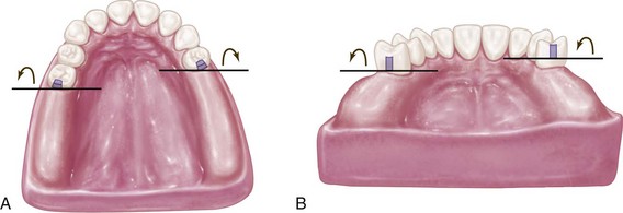
Figure 7-46 A, Axes of rotation, although parallel, are not common because one axis is located anterior to the other axis. B, When one nonlocking internal attachment is elevated farther from the residual ridge than its cross-arch counterpart, the axes of rotation do not fall on a common line; thus some torquing of abutments should be anticipated. However, in many instances, the effect produced by this situation will not exceed physiologic tolerance of the supporting structures of the abutments—all other torquing factors being equal.
Other conservative treatment of partially edentulous arches with removable partial dentures can be accomplished in a variety of ways. Treatment is still contingent on the location and condition of the remaining teeth and the contour and quality of the residual ridges. Basic principles and concepts of design relative to support and stability must be respected even though a variety of retaining devices can be incorporated. Examples of some of these retaining devices are illustrated in Figures 7-47 through 7-50.
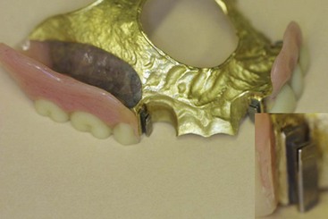
Figure 7-47 Classification II, modification 1 maxillary removable partial denture with three internal attachments. Gold framework with soldered attachments that gain retention through activation of the gingival region of the male component (see inset picture).
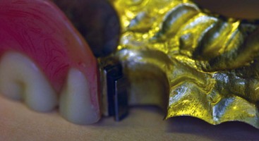
Figure 7-48 Same prosthesis as Figure 7-47, showing the attachment position relative to the framework palatal and distal minor connector components.
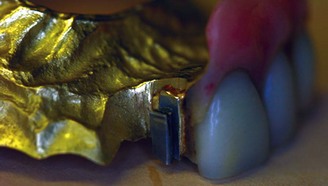
Figure 7-49 Similar photo as in Figure 7-48, showing the attachment at the anterior modification space. Careful arrangement of the components is required to maximize the esthetic advantage of attachment use in such a region.