28 CONNECTORS FOR PARTIAL FIXED DENTAL PROSTHESES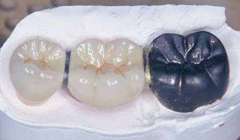
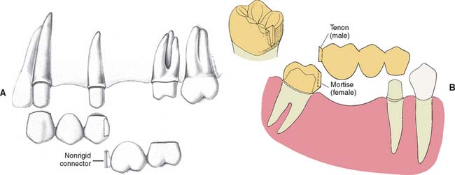
Connectors are the components of a partial fixed dental prosthesis (FDP) or splint that join the individual retainers and pontics together. Usually this is accomplished with rigid connectors (Fig. 28-1), although nonrigid connectors are occasionally used. The latter are usually indicated when it is impossible to prepare a common path of placement for the abutment preparations for a partial FDP (Fig. 28-2A and B). Their use has been reported to be associated with significantly reduced failure rates.1
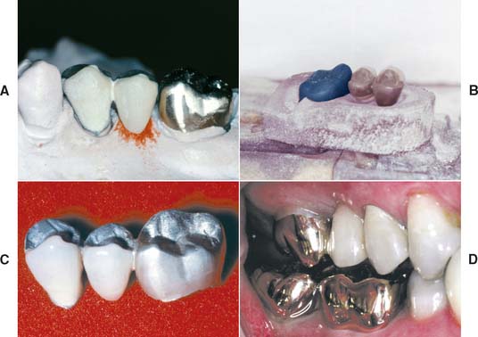
Fig. 28-1 Rigid connectors: A three-unit partial fixed dental prosthesis (FDP) replacing the maxillary second premolar. A, The anterior abutment and the pontic are connected with a rigid cast connector. These two partial FDP components are fabricated separately from the posterior abutment, which is cast in gold. B, The components are related to one another by a soldering assembly. C, The connected components. D, The fixed prosthesis in place.
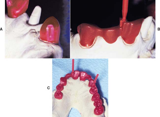
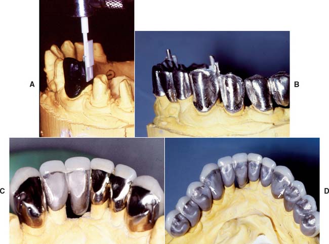
Fig. 28-2 Partial fixed dental prosthesis (FDP) with nonrigid connector. A, Mortise pattern (female) positioned on the distal aspect of the canine retainer. B, Partial FDP assembled with prefabricated resin tenon (male) on the mesial aspect of the pontic. C, Nonrigid connectors used to allow the fabrication of an extensive fixed prosthesis having abutments prepared with divergent paths of placement.
(Courtesy of Dr. M. Chen.)
RIGID CONNECTORS
Rigid connections in metal can be made by casting, soldering, or welding. Cast connectors are shaped in wax as part of a multiunit wax pattern. Cast connectors are convenient and minimize the number of steps involved in the laboratory fabrication. However, the fit of the individual retainers may be adversely affected because distortion more easily results when a multiunit wax pattern is removed from the die system. Soldered connectors involve the use of an intermediate metal alloy whose melting temperature is lower than that of the parent metal (Fig. 28-3). The parts being joined are not melted during soldering but must be thoroughly wettable by liquefied solder.2 Dirt or surface oxides on the connector surfaces can reduce wetting and impede successful soldering; for example, the solder may melt but does not flow into the soldering gap. Welding is another method of rigidly joining metal parts. In welding, the connection is created by melting adjacent surfaces with heat or pressure. A filler metal whose melting temperature is about the same as that of the parent metal can be used during welding.
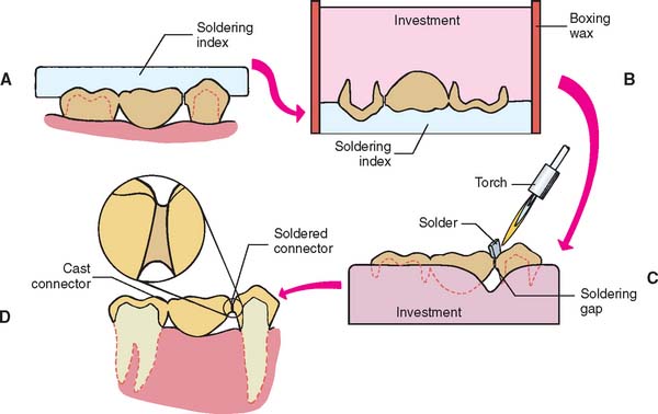
Fig. 28-3 The soldering process. A, Occlusal soldering index. B, Fixed dental prosthesis components invested. C, Torch soldering. D, Clinical evaluation.
In industrial metalworking, a distinction is made between soldering, in which the filler metal has a melting point below 450°C (842°F), and brazing, in which the filler has a melting point above 450°C.3 Rigid connections in dentistry are generally fabricated above 450°C, but the process has almost always been referred to in the dental literature as soldering. However, in a proposed international standard, the term brazing is used. With time, the latter term may become more generally accepted. In this text, however, the term soldering is used.
NONRIGID CONNECTORS
Nonrigid connectors are indicated when it is not possible to prepare two abutments for a partial FDP with a common path of placement. Segmenting the design of large, complex FDPs into shorter components that are easier to replace or repair individually is advisable. This can be helpful if there is uncertainty about an abutment’s prognosis. If the abutment fails, only a portion of the FDP may need to be remade. In the mandibular arch, nonrigid connectors are indicated when a complex FDP consists of anterior and posterior segments. During the mandibular opening and closing stroke, the mandible flexes mediolaterally.4 Rigid FDPs have been shown to inhibit mandibular flexure, and extensive splints have been shown to flex during forced opening.5 The associated stresses can cause dislodgment of complex FDPs. Segmenting complex mandibular FDPs can minimize this risk (Fig. 28-4).
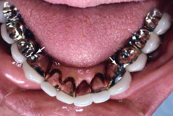
Fig. 28-4 To accommodate the stresses that potentially result from mandibular flexure, this complex fixed dental prosthesis has been segmented through the use of nonrigid connectors on the distal of the two canines (arrows).
(Courtesy of Dr. F. Hsu.)
Nonrigid connectors are generated through incorporation of prefabricated inserts in the wax pattern or through custom milling procedures after the first casting has been obtained. The second part is then custom-fitted to the milled retainer and cast. They are often made with prefabricated plastic patterns. The retainers are then cast separately and fitted to each other in metal.
CONNECTOR DESIGN
The size, shape, and position of connectors all influence the success of the prosthesis. Connectors must be sufficiently large to prevent distortion or fracture during function but not too large; otherwise, they interfere with effective plaque control and contribute to periodontal breakdown over time. Adequate access (i.e., embrasure space) must be available for oral hygiene aids cervical to the connector. If a connector is too large incisocervically, hygiene is impeded, and over time, periodontal failure will occur (Fig. 28-5A). For esthetic FDPs, a large connector or inappropriate shaping of the individual retainers may result in display of the metal connector, which may compromise the appearance of the restoration and lead to patient dissatisfaction (Fig. 28-5B).
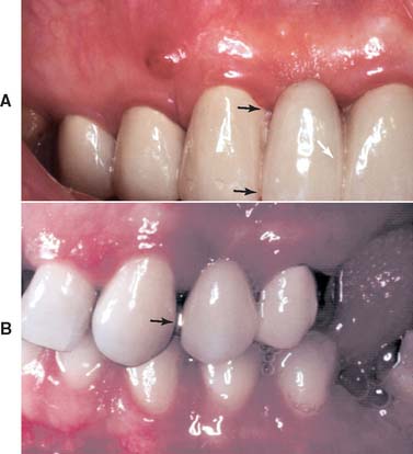
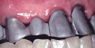
Fig. 28-5 Restorative failure. A, Incisocervically an excessively large connector (arrows) impedes proper plaque control and has led to periodontal breakdown. B, Although it may be acceptable from a biologic and mechanical perspective, a connector (arrow) that displays metal can prove to be esthetically unacceptable.
In addition to being highly polished, the tissue surface of connectors is curved faciolingually to facilitate cleansing. Mesiodistally, it is shaped to create a smooth transition from one partial FDP component to the next. A properly shaped connector has a configuration similar to a meniscus formed between the two parts of the prosthesis.
In a buccolingual cross-section, most connectors have a somewhat elliptical shape. Such an elliptical connector is strongest if the major axis of the ellipse parallels the direction of the applied force. Unfortunately, because of anatomic considerations, this cannot always be achieved. In fact, because of space constraints, the greatest dimension of most connectors is perpendicular to the direction of applied force, which tends to result in a weaker connector. For ease of plaque control, the connectors should occupy the normal anatomic interproximal contact areas, because encroaching on the buccal, gingival, or lingual embrasure restricts access. However, to improve appearance without significantly affecting plaque control, anterior connectors are normally placed toward the lingual embrasure. Figure 28-6 depicts typical locations for connectors on selected teeth.
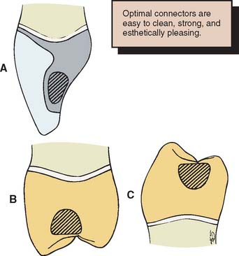
Fig. 28-6 Cross-sections through fixed dental prosthesis connectors. A, Maxillary anterior. B, Maxillary posterior. C, Mandibular posterior. Note the convexity of the gingival aspect of the connectors. To prevent excessive display of metal, anterior connectors should be placed toward the lingual embrasure.
Pulp size and clinical crown height can be limiting factors in the design of nonrigid connectors. Most prefabricated patterns require the preparation of a fairly sizable box. This allows incorporation of the mortise (see p. 843; Fig. 28-9B) in the cast restoration without overcontouring of the interproximal emergence profile. Short clinical crowns do not provide adequate occlusocervical space to ensure adequate strength. Most manufacturers recommend 3 to 4 mm of vertical height.
TYPES OF CONNECTORS
Rigid Connectors
Rigid connectors must be shaped and incorporated into the wax pattern after the individual retainers and pontics have been completed to final contour but before reflowing of the margins for investing (see Chapter 18).
Cast connectors
Connectors to be cast are also waxed on the definitive cast before reflowing and investing of the pattern. The presence of a cast connector makes the latter somewhat more awkward. Access to the proximal margin is impeded, and the pattern cannot be held proximally during removal from the die. Restricting cast connectors to complete coverage restorations, which can be gripped buccolingually, is therefore advisable. Partial-coverage wax patterns are easily distorted when they are part of a single-cast partial FDP. One-piece castings often appear to simplify fabrication but tend to create more problems than do soldered connectors, especially as pattern complexity increases.
Soldered connectors
As with cast connectors, connectors to be soldered are waxed to final shape but are then sectioned with a thin ribbon saw (Fig. 28-7A and B); therefore, when the components are cast, the surfaces to be joined are flat, parallel, and a controlled distance apart. This allows accurate soldering with a minimum of distortion.6 Molten solder flows toward the location where the temperature is highest. In metal, the two flat surfaces previously created in wax retain heat, ensuring that the highest temperature is in the connector area.
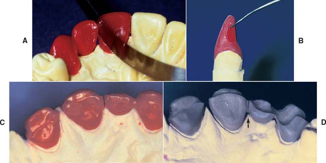
Fig. 28-7 Connector design. A, A ribbon saw is used to section the wax pattern. B, The sectioned surface should be flat and located sufficiently far incisally and lingually to allow adequate hygiene and esthetics of the completed partial fixed dental prosthesis (FDP). C, A three-unit FDP after sectioning. D, Framework ready for porcelain application. Note the uniform gap width (arrow).
Soldering gap width
As gap width increases, soldering accuracy decreases.7 Extremely small gap widths can prevent proper solder flow and lead to an incomplete or weak joint.8 An even soldering gap of about 0.25 mm is recommended. If a connector area has an uneven soldering gap width, obtaining a connector of adequate cross-sectional dimension without resulting distortion is more difficult.
Loop connectors
Although they are rarely used, loop connectors (Fig. 28-8) are sometimes required when an existing diastema is to be maintained in a planned fixed prosthesis. The connector consists of a loop on the lingual aspect of the prosthesis that connects adjacent retainers and/or pontics.
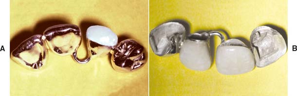
Fig. 28-8 In the presence of a diastema that is to be maintained, a loop connector may be indicated. Incisal (A) and labial (B) views of a four-unit fixed dental prosthesis with a loop connector. Note that the diastema between the lateral and central incisors is maintained.
(Courtesy of Dr. M. T. Barco.)
The loop may be cast from sprue wax that is circular in cross-section or shaped from a platinum-gold-palladium (Pt-Au-Pd) alloy wire. Meticulous design is important for enabling plaque control.
Nonrigid Connectors
The design of nonrigid connectors that are incorporated in the wax pattern stage consists of a mortise (also referred to as the female component) prepared within the contours of the retainer and a tenon (male component) attached to the pontic (Fig. 28-9). The mortise is usually placed on the distal aspect of the anterior retainer. Accurate alignment of the dovetail or cylindrically shaped mortise is crucial; it must parallel the path of placement of the distal retainer (see Fig. 28-2). Paralleling is normally accomplished with a dental surveyor. When the cast is aligned, the path of placement of the retainer that will be contiguous with the tenon is identified. The mortise in the other retainer is then shaped so that its path of placement allows concurrent seating of the tenon and its corresponding retainer.
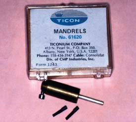
The mortise can be prepared freehand in the wax pattern or with a precision milling machine. Another approach is to use prefabricated plastic components for the mortise and tenon of a nonrigid connector (Fig. 28-10). As an alternative, a special mandrel can be embedded in the wax pattern (Fig. 28-11) and the abutment retainer can be cast, with refinement of the female component as necessary; the male key is then fabricated with autopolymerizing acrylic resin and attached to the pontic.
MATERIALS SCIENCE
Solder
Dental gold solders are given a fineness designation to indicate the proportion of pure gold contained in 1000 parts of alloy. For example, a 650-fine solder contains 65% gold. In an earlier designation,9 the solder was assigned a carat number, which indicated the gold content of the castings that were to be joined with the solder; an 18-carat solder could be used to solder castings fabricated of an alloy containing 75% gold. Because numerous alloys other than type IV gold are available today, many of which contain platinum-group metals, the carat designation is of little value.
Modern casting alloys have become so metal-lurgically complex that most manufacturers now recommend specifically formulated solders. One manufacturer (Heraeus Kulzer) classifies traditional gold-containing solders as group I and others (termed special solders) as group II. Most of these have the brand name with a “pre” or “post” designation to indicate whether the solder is to be used for joining the components before or after porcelain application. The preceramic solders are obviously high-fusing alloys, sometimes fusing only slightly beneath the softening point of the parent alloy to be joined. Ideally, they flow well above the fusion range of the subsequently applied porcelain. Postceramic solders must flow well below the pyroplastic range of the porcelain. For example, one popular silver-palladium (Ag-Pd) casting alloy has a specified melting range between 1232° and 1304°C (2280° to 2384° F). The recommended special presolder melts at 1110°C to 1127°C (2030°F to 2061°F), whereas the postsolder melts at 710°C to 743°C (1310°F to 1369°F). The porcelain fuses at about 982°C (1800°F), depending on time and temperature.
The composition of the solder determines its melting range, among other things. Some typical compositions and melting ranges are given in Table 28-1. Solder’s main requirement is to fuse safely below the sag or creep temperature of the casting to be soldered. Newer palladium casting alloys, by virtue of their higher melting ranges, have somewhat increased the reliability of the preceramic application soldering technique.10

However, preceramic soldering is relatively difficult and can be structurally hazardous (Fig. 28-12). This may be because of the volatilization of base metal solder constituents that occurs with overheating.11 Volatilization then results in microporosity or pitting. The melting range of presolders is quite narrow, because silver and copper (the usual modifiers of temperature range) cannot be used in the alloy; these elements discolor porcelain on contact. Another consideration is the oxide necessary for the chemical adherence of porcelain. Porcelain does not chemically bond equally well to all solders.
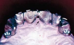
Fig. 28-12 Metal substructure for an anterior prosthesis. The preceramic soldering procedure has led to partial melting of the framework (arrow), which can result in distortion and/or premature failure.
Other requirements of solders are their ability to resist tarnish and corrosion, to be free flowing, to match the color of the units that will be joined, and to be strong. These factors also depend on the chemical composition of the solder.
Resistance to tarnish and corrosion is determined by a solder’s noble or precious metal content and its silver/copper (Ag/Cu) ratio.12 In addition, if the compositions of the solder and work piece differ, galvanic corrosion may occur.
During the soldering procedure, the solder must flow freely over clean and smooth surfaces. These surfaces should be smoothed with abrasive disks, not with rubber wheels or polishing compounds. The phenomenon of free flow is termed wetting, during which remelting or realloying of the surface of the units to be joined must not occur.13 Solder flow is increased by the addition of silver and decreased by the presence of copper. Figure 28-13 demonstrates a properly made solder joint. Note that the filler metal has joined the surfaces of the two castings without penetrating either one.
Lower-fineness gold solders are often more fluid and are generally chosen for joining castings. If necessary, proximal contacts with a solder of higher fineness can also be added, because this tends to flow less freely. However, the exact minimally acceptable fineness necessary for resisting tarnish and corrosion has not been conclusively established; 615 or 580 fineness is probably the lower limit of clinical acceptability.
The last requirement, strength, is easily satisfied by most solders and is usually greater than that of the soldered parent metal, provided that the procedure is followed carefully.8 In addition, most solders harden during cooling because of the “order-disorder” transformation and the formation of other intermetallic phases, which occur at grain boundaries. Brittleness is frequently encountered with gold-based copper-containing solders. As with type III and type IV gold casting alloys, the gold-copper order-disorder (or discontinuous phase-hardening) mechanism causes similar changes in the solder’s microstructure.14 Simply stated, with these solders, cooling to room temperature results in a brittle joint. The joints are strong but have no ductility. Some solder joints are weakened by notches.15 This means that soldered connectors should be well-polished to prevent fracture.
Partial FDPs fabricated with type III gold alloys and joined interproximally with traditional gold-based solders are usually water quenched 4 to 5 minutes after soldering is complete. Quenching immediately after soldering causes the partial FDP to warp; failure to quench leads to creation of a joint with little or no ductility. A brittle joint may easily fracture. Thus, a disadvantage of postceramic soldering is the loss of joint ductility. Because the components are partially porcelain, quenching is not done, because porcelain fracture will occur.
Soldering Flux and Antiflux
Soldering flux
This substance is applied to a metal surface to remove oxides or prevent their formation. When the oxides are removed, the solder is free to wet the clean metal surface.
Borax glass (Na2B4O7) is frequently used with gold alloys because of its affinity for copper oxides. An often-cited soldering flux formula16 is borax glass (55 parts), boric acid (35 parts), and silica (10 parts). These ingredients are fused together and then ground into a powder.
Fluxes are available in powder, liquid, or paste form. The paste is popular because it can be easily placed and confined. Pastes are made by mixing the flux powder with petrolatum. The petrolatum excludes oxygen during heating and eventually carbonizes and then vaporizes.
New fluxes are available for use with non–gold-based alloys. Their formulas are not generally published. At present, none of the new fluxes are totally capable of preventing oxide formation during heating of the base metal or nonnoble alloys. An example of a rapidly forming oxide on a base metal occurring during a simulated postceramic application soldering can be seen in Figure 28-14. Soldering of base metal alloys is still unpredictable.17
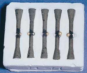
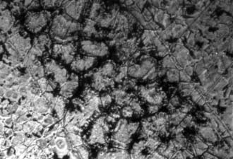
Fig. 28-14 Simulated base metal-to-base metal postceramic soldering procedure. Excessive oxide formation has prevented wetting by the solder.
(From Sloan RH, et al: Post-ceramic soldering of various alloys. J Prosthet Dent 48:686, 1982.)
All fluxes should be kept from contacting porcelain-veneered surfaces. The contact causes pitting and porcelain discoloration.
Soldering antiflux
Antiflux is used to limit the spreading of solder. It is placed on a casting before the flux application to limit the flow of molten solder. When the metal surfaces are clean, any excess solder introduced into the work gap tends to flow into undesirable areas. The antiflux helps prevent this.
Graphite (from a pencil) is often used as an antiflux. However, the carbon easily evaporates at higher temperature, leaving the work piece unprotected. A more reliable antiflux is iron oxide (rouge) in a suitable solvent such as turpentine, which can be painted on the casting with a small brush.
Soldering Investment
Soldering investments are similar in composition to casting investments (see Chapter 22). Casting investments, both gypsum and phosphate bonded, mixed with water only, have been used for soldering. However, the refractory component in casting investments usually creates unwanted thermal expansion and therefore excessively separates the units to be joined. Soldering investments ideally contain fused quartz (the lowest thermally expanding form of silica) as their refractory component.
Invested units expand during heating, and they should do so at the same rate as the castings. The units must be correctly gapped so that they do not touch. When the work units are allowed to touch, distortion and porous inadequate joints result.9 Alternatively, excessive gap spaces cause undersized mesiodistal partial FDP widths because of solder solidification shrinkage. However, Ryge9 showed that the gap space closes somewhat during heating, and so it is doubtful that the alloy and investment truly expand equally or at the same rates. Several commercial soldering investments are available; these should be used whenever possible. A list of reliable investments appears in Appendix A.
Joining Base Metals
Titanium and titanium alloys
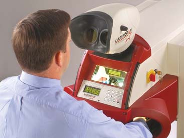
The advent of titanium and its alloys, as with cobalt-chromium-nickel, has brought a new challenge to joining cast units. Titanium also responds to high heat with an increased oxide formation, which results in a poor union between components to be joined. A reasonable solution has proved to be welding, by either laser or plasma. Advantages include less heat distortion and a compositionally uniform joint. Thus, joining with the same chemical element or elements minimizes detrimental galvanic degradation. Figure 28-15 shows a “stepped” laser weld. Much work yet remains to render titanium a suitable replacement for noble casting alloys.
SELECTION OF SOLDERING TECHNIQUE
When partial FDPs are assembled by soldering, the relative position of the components is recorded with a soldering index on the definitive cast or intraorally. If pontics are made individually, they can be difficult to position properly in relation to the abutment teeth. Although a positioning index made previously upon completion of the wax pattern can be helpful (Fig. 28-16), the pontics should be connected to one of the retainers with a cast connector because this stabilizes them and makes accurate positioning in relation to the other retainer much easier. To understand the selection of soldering technique, a thorough knowledge of the fusing ranges of all materials involved in the FDP is essential (Fig. 28-17).
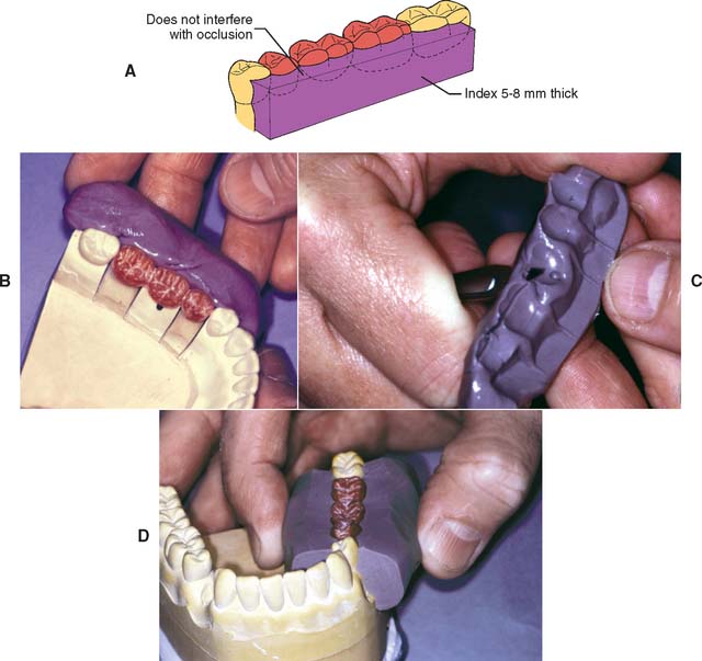
Fig. 28-16 Once the fixed dental prosthesis has been waxed to anatomic contour, a silicone putty buccal index (A) can be made. This can be helpful when relating the castings. B, Putty is applied to the buccal aspect of the completed waxing. C, Excess is trimmed away with a scalpel blade. D, The flat surface makes verification of accurate reseating of the index much easier.

Fig. 28-17 A, Casting metal-ceramic alloys. B, Presoldering. C, Porcelain firing. D, Casting type III and type IV gold alloy. E, Postceramic soldering. F, Conventional soldering.
Soldering of all-metal FDPs consisting of type III or IV gold units requires the use of a low-fusing solder. The procedure is referred to as conventional soldering. Through the use of the same low-fusing solder, regular gold retainers can also be connected with metal-ceramic components. A gas-air torch is used for either of these procedures.
For FDPs consisting of metal-ceramic units, the soldered connectors may be made either before the ceramic application with high-fusing solder (approximately 1100°C [2012°F]) or after the ceramic application with lower-fusing solder (750°C [1382°F]). Soldering before ceramic application is called pre-ceramic application soldering or pre-soldering. Soldering of metal-ceramic crowns after their completion is referred to as post-soldering. Many alloys can be combined by using either pre-ceramic or post-ceramic soldering. However, pre-soldering has been found to be less reliable,8 with a number of apparently sound connectors exhibiting negligible tensile strength. Considerable variation in solder joint strength has also been recorded after laboratory testing,18 which emphasizes the special care needed to avoid defective connectors.
Base metal alloys can be difficult to solder because they oxidize; oxidation must be controlled with special fluxes, although excessive fluxing can lead to undesirable inclusions and weak connectors. In one study,19 investigators found that 20% of post-ceramic soldered joints involving base metal alloys had to be resoldered because they were so weak that they broke with finger pressure. Another study20 showed great variability in solder joint quality with these alloys, with no consistent relationship of strength to gap width. Those authors found that most failures occurred through the solder and were attributable to voids caused by gas entrapment or localized shrinkage. With experience and careful adherence to the manufacturer’s recommended techniques and materials, reliable base metal alloy soldered connectors are possible.21 However, because of the problems of soldering base metal alloys, various alternative procedures have been advocated. These include making the soldered joint through the center of the pontic to increase the area soldered22 and connecting the parts by a second casting procedure, with the molten metal flowing into undercuts in the sectioned pontic.23
Soldering All-Metal Partial Fixed Dental Prostheses
Type III and type IV gold retainers of partial FDPs are soldered with gold solder ranging from 615 to 650 fineness. An occlusal plaster index or autopolymerizing resin index is fabricated intraorally or in the dental laboratory; after investing, a gas-air torch can be used to solder the components. A disadvantage of the soldering procedure is that it requires an additional step, in comparison with a one-piece casting. However, soldering simplifies the manipulation of wax patterns. For instance, when a three-abutment FDP with two splinted abutments (e.g., two premolars) is fabricated, access to the interproximal margins of the two splinted abutments is often very difficult during the reflowing and finishing steps. Soldering such retainers enables the retainers to be shaped and adjusted individually with improved access for finishing procedures. Conventional soldering requires a gas-air torch; soldering can also be performed in a furnace.
Soldering Metal-Ceramic Partial Fixed Dental Prostheses
Pre-ceramic soldering
Once a metal-ceramic framework has been assembled by pre-ceramic application soldering, the subsequent procedures are the same as if it had been cast in one piece. This has the advantage of allowing the connected prosthesis to be tried in the mouth in the unglazed state. Any necessary adjustments can be made to the porcelain, which fuses at a lower temperature than does the pre-ceramic soldered connector. However, with pre-ceramic soldering, contouring the proximal embrasures so that the units resemble natural teeth may be more difficult. A very thin diamond disk is helpful for this.
A disadvantage results from having to apply the porcelain to a longer structure, which needs support during firing to prevent high-temperature deformation or sag. Sag can be a particular problem with the high-gold content ceramic alloys because they have a lower melting range. High–palladium content or base metal alloys exhibit little sag during firing. Pre-soldering requires a gas-oxygen torch.
Post-ceramic soldering
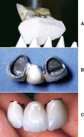
Post-ceramic soldering is necessary when regular gold and metal-ceramic units are being combined in a partial FDP. The regular gold melts if it is subjected to the high temperatures needed for porcelain application; therefore, all porcelain adjustment and firing, including that for the final characterization and glazing, must be completed before the soldering. If further corrective adjustment is needed after soldering, the porcelain must be polished, or the joint must be separated, after which additional porcelain can be added as needed, the restorations can be reglazed, a new index can be made, and the FDP resoldered.
Because the proximal areas are shaped before soldering, a postsoldered connector can often be made to look more natural than a presoldered or cast connector (Fig. 28-18). In addition, customized firing supports are not needed because sag is not a problem (the lengths of the individual components are shorter). Postsoldering is performed either in a porcelain furnace or with a gas-air torch.
HEAT SOURCES
Torch Soldering
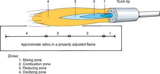
When a gas-air torch is used as the heat source to melt the solder, metal-ceramic restorations are preheated in an oven to minimize the risk of cracking of the porcelain veneer. Oxidization of the joint surfaces is prevented by using the reducing portion of the flame (Fig. 28-19) and by applying an appropriate flux (some soldering fluxes are unsuitable because they discolor the porcelain). To prevent uneven heat distribution, which could result in fracture, the flame is never concentrated in one area but is kept in constant motion.
Some dentists believe that the flow of solder is more controllable during torch soldering because a slight temperature differential can be created and the solder always flows toward the hotter point. This makes torch soldering useful when the connector has not been well designed in wax, and a minor temperature difference can deliberately be created in the assembly to help direct the flow of the molten solder to ensure an adequate connector.
Oven Soldering
Furnace or oven soldering is performed under vacuum or in air. A piece of solder is placed at the joint space, and the casting and solder are heated simultaneously.
Criticism of this technique has been based on earlier observations24 that less porosity resulted when castings were brought to soldering temperature before the solder was applied. The method does not allow the moment of solder fusion to be observed.* This may be important, because the longer the solder remains molten, the more it dissolves the parent metal and consequently weakens the joint.9 Nevertheless, joints with strength similar or superior to that of the parent metal have been demonstrated8 when oven soldering was used.
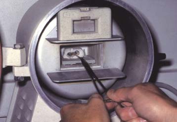
A different technique may be appropriate if the porcelain furnace has a horizontal muffle with a fixed floor. The soldering assembly is heated above the fusion point of the solder, the muffle door is opened, and the solder is fed into the joint space (Fig. 28-20).
Laser Welding
Laser energy is extensively used for welding (Fig. 28-21) in many industries and has been described in dentistry since the 1970s.25,26 Interest has continued in laser assembly of fixed prostheses with reportedly higher strength27 and reduced corrosion28 compared with conventional soldering, although laser-welded connectors seem as susceptible to fatigue failure.29 Laser welding may be a practical way to join cast titanium components (e.g., if these are to be used for implant-supported prosthesis frameworks30,31).
SOLDERING ACCURACY
Controversy exists as to the relative accuracy of partial FDPs that are cast in one piece, preceramic soldered, or postceramic soldered. Individual laboratory technicians often obtain consistently better results with one particular technique, but scientific evidence is conflicting.32,33 In evaluating clinical work to determine whether cast or soldered connectors provide better results, the determining factor should be the fit of the individual retainers. This should be optimized through the investing and casting process (see Chapter 22) to minimize the risks of incomplete seating or excessive luting agent space. In some situations, it may be impossible to cast a long-span FDP with ideal retainer dimensions and ideal interabutment dimensions; the challenge lies in obtaining enough interabutment expansion without making the retainers too loose. In such circumstances, a soldered connector may provide better accuracy. The situation is reversed for fabricating frameworks for implant-supported prostheses (see Chapter 13). Here the fit of the individual units is determined by the implant manufacturer. Only the overall abutment-to-abutment fit is under the control of the technician. However, an accurate, passively fitting implant-supported framework is crucial for avoiding damaging forces. It is not yet clear whether accurate implant-supported frameworks are most effectively made with one-piece castings or as sectioned and soldered units.34
SOLDERING TECHNIQUE
Step-by-Step Procedure
Occlusal soldering index
An intraoral plaster or ZOE impression is made of the occlusal surfaces of the partial FDP to capture the relative relationship of the individual FDP components and transfer this to the laboratory. This procedure can also be performed in the laboratory if the technician is satisfied that the individual components are seated completely on an accurate definitive cast. An advantage of an occlusal index (Fig. 28-22; see Fig. 28-3) is that after the soldering procedure has been completed, the FDP can be reseated in the index and soldering accuracy can be verified (sometimes a small amount of plaster must be removed in the area where the solder has been added, to ensure seating).
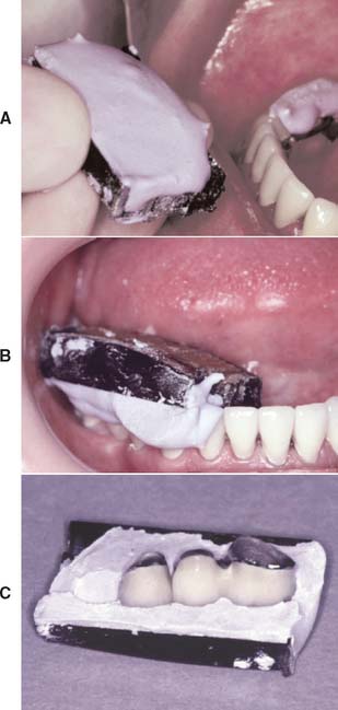
Fig. 28-22 Soldering index (plaster) for posterior fixed dental prostheses. A, A suitable carrier (e.g., baseplate wax) is trimmed to proper shape before a registration is made with impression plaster (B). C, The plaster occlusal registration.
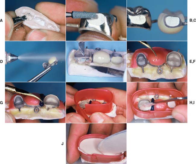
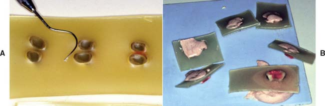
Fig. 28-23 Investing procedure (occlusal index). A, The index is trimmed to ensure complete seating of the castings. B and C, The connector area is ground with a noncontaminating stone. D, The restorations are steam cleaned. (Alternatively, an ultrasonic can be used.) E, The castings are seated firmly and luted to place with sticky wax. F, Glazed porcelain is damaged by contact with the investment; the porcelain is therefore protected with a layer of wax. G, The wax is flowed into the connector areas and is adapted below each connector to create an airway. H, The soldering assembly is boxed. I and J, When the assembly is filled with soldering investment, great care is taken to ensure that there are no air bubbles in the investment.
Investing
Autopolymerizing resin soldering index
A plaster or ZOE occlusal index is less suitable for the registration of anterior restorations. The thinness of the incisal edges of these units makes them less stable, and accurate repositioning is more difficult. For this reason, autopolymerizing resin (Fig. 28-24) is recommended, although the resin burns off during the procedure. Therefore, the accuracy of the soldering procedure can be verified only intraorally.
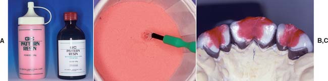
Fig. 28-24 Soldering index (autopolymerizing resin). A, Armamentarium. B, A small brush dipped in resin monomer is touched to the polymer powder. This forms a bead. C, The restorations are thus connected, with resin extending onto the incisal edges of all the retainers.
Investing (Fig. 28-25)
Wax removal and preheating (Fig. 28-26).
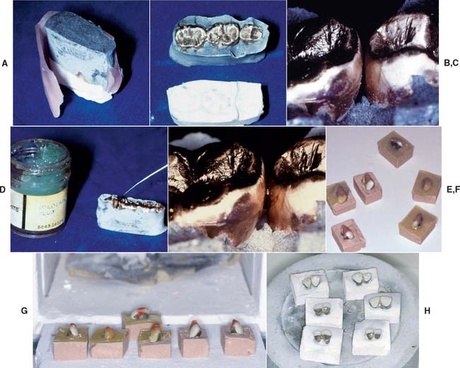
Fig. 28-26 Wax removal and preheating. A and B, Boxing material removed and the wax residue flushed out with boiling water. C, The connector area must be free of contaminants. D, A small amount of soldering flux is applied while the assembly is still warm. E, The flux is carried into the connector area by capillary action. Then the assembly is placed in the burnout furnace. F and G, Autopolymerizing resin indexes. These are burned off directly in the furnace after wax elimination. H, The soldered restorations.
Torch soldering (low heat) (Fig. 28-27)
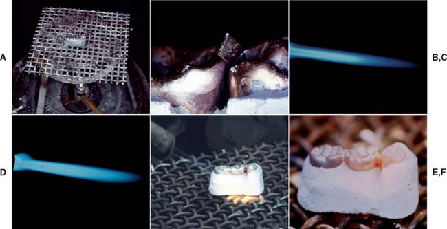
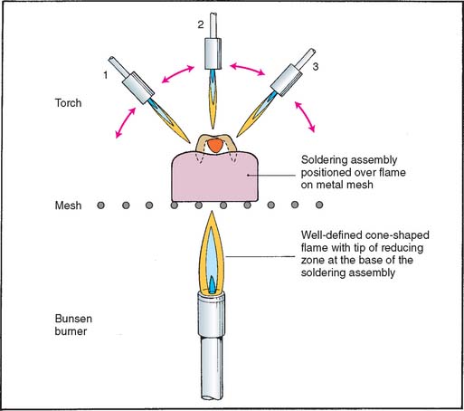
Fig. 28-27 Low-heat torch soldering. A, The assembly positioned on a wire mesh over a Bunsen burner. B, A flexed piece of solder placed into the connector area. C, A sharply defined flame is preferable for casting procedures. D, A brush flame is more suitable for soldering. This can be obtained by slightly reducing the amount of air. E, The assembly is heated evenly until the solder melts. The solder must “spin” in the connector area to form a complete connection (F).
Torch soldering (high heat) (Fig. 28-28)
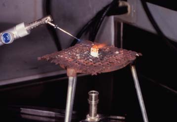
Fig. 28-28 High-heat (pre-ceramic application) torch soldering with a gas-oxygen torch and a miniature needle tip.
Oven soldering (Fig. 28-31)
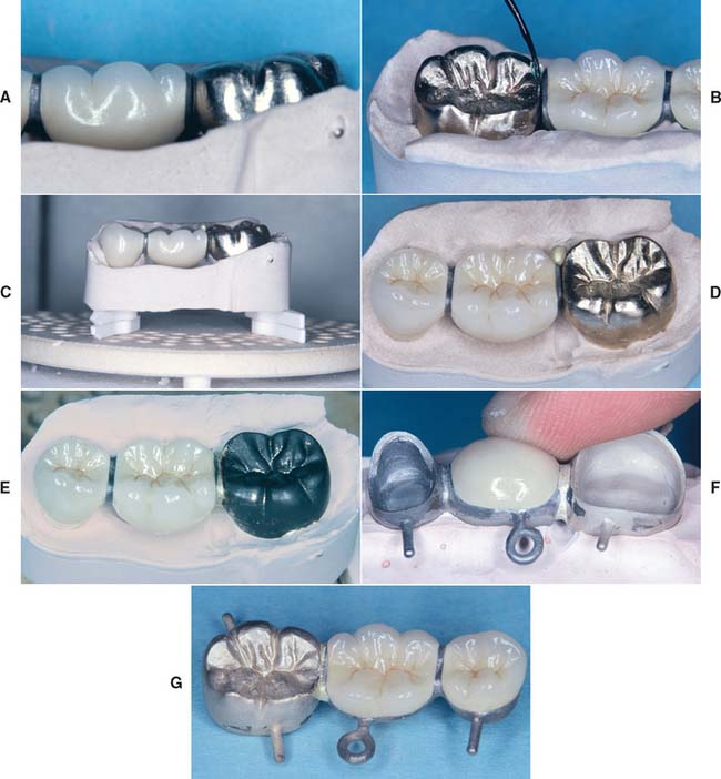
Fig. 28-31 Oven soldering procedure. A, The invested partial fixed dental prosthesis (FDP) before soldering. B, A small amount of flux is added to the clean joint area. C and D, Solder is added, and the assembly placed in the oven. E, The soldered FDP. F, The soldering index is used to assess soldering accuracy. G, Oven-soldered connector before finishing.
Evaluation
If the solder fails to flow during torch soldering but forms a ball above the joint area, heating should be discontinued. The solder has oxidized, and further heating will melt the castings. If the solder has flowed properly, the completed joint can be evaluated for size before removal of the investment and, if necessary, reheated while still hot, with additional solder added. Excessive solder must be ground away during the finishing procedure (Fig. 28-32).
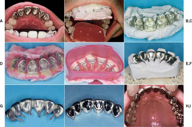
Fig. 28-32 A, A fixed splint was indicated for this patient to prevent drifting of teeth with compromised periodontal support. B and C, Plaster soldering index. D and E, Splint before investing. F, The soldering assembly. G, The assembled prosthesis after soldering. H, Note that the connectors have been considerably reduced in size during the finishing procedure. Splinted teeth do not require as large connectors as do fixed dental prostheses. I, The completed prosthesis.
If the connector has been designed properly and the solder has been properly positioned, no solder should run onto the occlusal surface or cover the margins. To prevent stray flow, a small amount of antiflux (rouge dissolved in turpentine) can be painted on critical areas before the assembly is heated. After bench cooling for about 5 minutes, the assembly is quenched (not porcelain) and the investment broken away (Fig. 28-33). The connector is then carefully inspected. If signs of an incomplete joint are evident (e.g., visible porosity in the solder), they are removed by grinding with a fine disk; the units are then reinvested and resoldered.
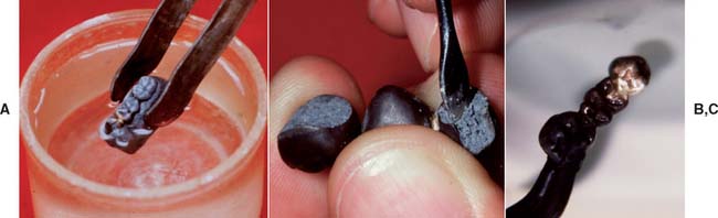
Fig. 28-33 A, The assembly is quenched after bench cooling for approximately 5 minutes. B, Investment removed from the castings. C, Surface oxides dissolved in a pickling solution.
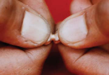
The joints must be tested for strength (Fig. 28-34). Any connector that can be broken by force of hand will not serve adequately in the mouth. Because broken connectors cannot be easily repaired intraorally once the prosthesis has been cemented, the entire restoration usually must be remade.
REVIEW OF TECHNIQUE
Figure 28-35 summarizes the steps involved in partial FDP connector fabrication and should be referred to when the material is reviewed.
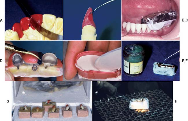
Fig. 28-35 Technique review. A, The design of connectors is determined in the wax pattern. B, All soldered connections require clean parallel surfaces. Gap width should be 0.25 mm. C, The units are indexed either from the definitive cast or in the mouth. D, Wax is added to the indexed restorations to shape the soldering assembly. For metal-ceramic restorations, it is added to protect the porcelain. E, The units are invested, and the investment is allowed to bench set. F, If a plaster or zinc oxide–eugenol index is used, wax is eliminated with boiling water, the joint is fluxed, and the assembly is preheated in a burnout furnace. G, If a resin index has been used, it is placed directly in the burnout furnace. H, The connectors are soldered with a torch or in a porcelain furnace.
SUMMARY
Connectors join individual retainers and pontics. Rigid or nonrigid connectors can be used. Connector size, shape, and position influence the success of a partial FDP. The use of soldered connectors can simplify the fabrication of larger fixed prostheses, which may be cast separately in groups of one or two units and assembled after their individual fit has been verified. The technical procedures involved in soldering are not difficult. If the joint surfaces have been correctly designed and soldering gap width has been carefully controlled, the procedures are routine. All debris must be removed from the connector area because it interferes with surface wetting.
Conventional soldering involves the assembly of type II, III, or IV gold castings. Pre-soldering is the assembly of metal ceramic substructures before porcelain application. Post-soldering is the assembly of metal ceramic units after porcelain application. Heat sources used for soldering procedures include gas-air torches, gas-oxygen torches, furnaces, and laser units.
If the basic principles are understood and the technique has been mastered, these procedures are entirely reliable.
 GLOSSARY*
1abra·sive \uh-brā′ siv, -ziv\ n (1853): a substance used for abrading, smoothing, or polishing
airborne-particle abrasion \âr′bôrn′ pär′t -kal a-brā′zhun\: the process of altering the surface of a material through the use of abrasive particles propelled by compressed air or other gases
antiflux \ăn′tē-flŭks′\ n: materials that prevent or confines solder attachment or flow
bees’ wax n (1676): a low-melting wax obtained from honeycomb and used as an ingredient of many dental impression waxes
brazing investment \brā′zing n-v st′ment\: an investment having a binding system consisting of acidic phosphate such as monoammonium phosphate and a basic oxide such as magnesium oxide
brazing material \brā′zing ma-tîr′ē-al\: an alloy suitable for use as a filler material in operations with which dental alloy(s) is/are joined to form a dental restoration
cast connector: a cast metal union between the retainer(s) and pontic(s) in a fixed dental prosthesis
1con·nec·tor \ka-nk′tor\ n (15c): in removable denture prosthodontics, the portion of a removable dental prosthesis that unites its components—usage: see BAR C., CONTINUOUS BAR C., MAJOR C., MINOR C.
di·a·ste·ma \dī′a-stē′ma\ n, pl -ma·ta \-ma-ta\ (1854): a space between two adjacent teeth in the same dental arch
fine \fīn\ adj (13c) 1: free from impurities 2: of a metal: having a stated proportion of pure metal in its composition, expressed in parts per thousand > a gold coin 0.9265
fine·ness \fīn′ns′\ n: the proportion of pure gold in a gold alloy; the parts per 1000 of gold
flux \flŭks\ n (14c) 1: in physics, the rate of flow of a liquid, particles or energy 2: in ceramics, an agent that lowers the fusion temperature of porcelain 3: in metallurgy, a substance used to increase fluidity and to prevent or reduce oxidation of a molten metal 4: any substance applied to surfaces to be joined by brazing, soldering or welding to clean and free them from oxides and promote union
in·dex \n′dks′\ n (1571): a core or mold used to record or maintain the relative position of a tooth or teeth to one another, to a cast, or to some other structure
infrared radiation \n′fra-rd\: electromagnetic radiation of wavelengths between 760 nm and 1000 nm
laser welding \lā′zer wl′dng\: the joining of metal components through the use of heat generated with a laser beam
nonrigid connector \n n-rj′d ka-nk′tor\: any connector that permits limited movement between otherwise independent members of a fixed dental prosthesis
rigid connector \rj′d ka-nk′tar\: a cast, soldered, or fused union between the retainer(s) and pontic(s)
1sol·der \sd′ar\ n (15c): a fusible metal alloy used to unite the edges or surfaces of two pieces of metal; something that unites or cements
2sol·der \sd′ar\ v, sol·der·ed \sd′ard\ sol·der·ing \sd′ar-ng\ sol·der·a·bil·i·ty \sd′ar-ă-bl′-tē\ n—sol·der·er \sd′ar-er\ n: to unite, bring into, or restore to a firm union; the act of uniting two pieces of metal by the proper alloy of metals
soldering antiflux: a material, such as iron oxide (rouge) dissolved in a suitable solvent such as turpentine placed on a metal surface to confine the flow of molten solder
sta·b·i·li·za·tion \stā′ba-l-zā′shun\ n, obs: the seating of a fixed or removable denture so that it will not tilt or be displaced under pressure (GPT-1)
stab·il·ize \stā′ba-līz′\ vb -liz·ed \līzd\ -liz·ing \lī-zng\ vt, stabilization \stā′ba-l-zā′shun\ v (1861) 1: to make firm, steadfast, stable 2: to hold steady, as to maintain the stability of any object by means of a stabilizer
subocclusal connector \sŭb′a-klōō′zal ka-nk′tar\: an interproximal nonrigid connector positioned apical to and not in communication with the occlusal plane
2weld \wld\ vb: to unite or fuse two pieces by hammering, compression, or by rendering soft by heat with the addition of a fusible material
STUDY QUESTIONS
1 Walton TR. An up to 15-year longitudinal study of 515 metal-ceramic FPDs: Part 2. Modes of failure and influence of various clinical characteristics. Int J Prosthodont. 2003;16:177.
2 Anusavice KJ. Phillips’ Science of Dental Materials, 11th ed., Philadelphia: WB Saunders; 2003:608.
3 British Standard Institute. British Standard Glossary of Dental Terms. London: British Standard Institute, 1983.
4 Goodkind RJ, Heringlake CB. Mandibular flexure in opening and closing movements. J Prosthet Dent. 1973;30:134.
5 Fischman BM. The influence of fixed splints on mandibular flexure. J Prosthet Dent. 1976;35:643.
6 Steinman RR. Warpage produced by soldering with dental solders and gold alloys. J Prosthet Dent. 1954;4:384.
7 Willis LM, Nicholls JI. Distortion in dental soldering as affected by gap distance. J Prosthet Dent. 1980;43:272.
8 Stade EH, et al. Preceramic and postceramic solder joints. J Prosthet Dent. 1975;34:527.
9 Ryge G. Dental soldering procedures. Dent Clin North Am. 1958;2:747.
10 Rasmussen EJ, et al. An investigation of tensile strength of dental solder joints. J Prosthet Dent. 1979;41:418.
11 Craig RG, Powers J. Restorative Dental Materials, 11th ed. St. Louis: Mosby, 2002.
12 Tucillo JJ. Compositional and functional characteristics of precious metal alloys for dental restorations. In: Valega TM, editor. Alternatives to Gold Alloys in Dentistry [U.S. DHEW Publication No. (NIH) 77–1227]. Washington, DC: Deptartment of Health, Education, and Welfare, Public Health Service, National Institutes of Health; 1977:40.
13 El-Ebrashi MK, et al. Electron microscopy of gold soldered joints. J Dent Res. 1968;47:5.
14 Leinfelder KF, et al. Hardening of dental gold-copper alloys. Dent Res. 1972;51:900.
15 Chaves M, et al. Effects of three soldering techniques on the strength of high-palladium alloy solder. J Prosthet Dent. 1998;79:677.
16 Phillips RW. Skinner’s Science of Dental Materials, 8th ed. Philadelphia: WB Saunders, 1982.
17 Sloan RM, et al. Postceramic soldering of various alloys. J Prosthet Dent. 1982;48:686.
18 Beck DA, et al. A quantitative study of preporcelain soldered connector strength with palladium-based porcelain bonding alloys. J Prosthet Dent. 1986;56:301.
19 Staffanou RS, et al. Strength properties of soldered joints from various ceramic-metal combinations. J Prosthet Dent. 1980;43:31.
20 Anusavice KJ, et al. Flexure test evaluation of presoldered base metal alloys. J Prosthet Dent. 1985;54:507.
21 Sobieralski JA, et al. Torch versus oven precer-amic soldering of a nickel-chromium alloy. Quintessence Int. 1990;21:753.
22 Ferencz JL. Tensile strength analysis of midpontic soldering. J Prosthet Dent. 1987;57:696.
23 Fehling AW, et al. Cast connectors: an alternative to soldering base metal alloys. J Prosthet Dent. 1986;55:195.
24 Saxton PL. Post-soldering of nonprecious alloys. J Prosthet Dent. 1980;43:592.
25 Gordon TE, Smith DL. Laser welding of prostheses—an initial report. J Prosthet Dent. 1970;24:472.
26 Preston JD, Reisbick MH. Laser fusion of selected dental casting alloys. J Dent Res. 1975;54:232.
27 Kasenbacher A, Dielert E. Tests on laser-welded or laser-soldered gold and Co/Cr/Mo dental alloys. Dtsch Zahnarztl Z. 1988;43:400.
28 Van Benthem H, Vahl J. Corrosion behavior of laser-welded dental alloys. Dtsch Zahnarztl Z. 1988;43:569.
29 Wiskott HW, et al. Mechanical and elemental characterization of solder joints and welds using a gold-palladium alloy. J Prosthet Dent. 1997;77:607.
30 Sjögren G, et al. Laser welding of titanium in dentistry. Acta Odontol Scand. 1988;46:247.
31 Ortorp A, et al. Clinical experiences with laser-welded titanium frameworks supported by implants in the edentulous mandible: a 5-year follow-up study. Int J Prosthodont. 1999;12:65.
32 Gegauff AG, Rosenstiel SF. The seating of one-piece and soldered fixed partial dentures. J Prosthet Dent. 1989;62:292.
33 Sarfati E, Harter J-C. Comparative accuracy of fixed partial dentures made as one-piece castings or joined by solder. Int J Prosthodont. 1992;5:377.
34 Wee AG, et al. Strategies to achieve fit in implant prosthodontics: a review of the literature. Int J Prosthodont. 1999;12:167.
35 Lynch CD, McConnell RJ. Accurately locating the components of a fixed partial denture prior to soldering the connector: an intraoral technique. J Prosthet Dent. 2002;87:460.
36 Harper RJ, Nicholls JI. Distortions in indexing methods and investing media for soldering and remount procedures. J Prosthet Dent. 1979;42:172.
37 Moon PC, et al. Comparison of accuracy of soldering indices for fixed prostheses. J Prosthet Dent. 1978;40:35.
38 McDonnell T, et al. The effect of time lapse on the accuracy of two acrylic resins used to assemble an implant framework for soldering. J Prosthet Dent. 2004;91:538.