18 WAX PATTERNS
A large percentage of time and effort spent in fabricating fixed prostheses is devoted to producing a very accurate wax pattern. From this pattern, the finished cast restoration is duplicated by using the lost-wax process as part of the indirect procedure.
This technique consists of obtaining an accurate impression of the prepared tooth (Fig. 18-1A) and making a cast from the impression (Fig. 18-1B) on which a wax pattern that resembles the shape of the final restoration is shaped (Fig. 18-1C). A mold is then made around the wax pattern with a refractory investment material (Fig. 18-1D). When the investment has set, the wax is vaporized in an electric furnace. The hollow mold is then filled with molten casting alloy, reproducing every detail of the wax pattern (Fig. 18-1E). The metal casting is retrieved, excess metal is removed, and after polishing, the cast restoration is ready for clinical evaluation (Fig. 18-1F).
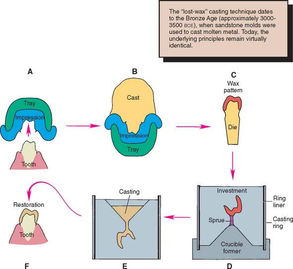
Fig. 18-1 Most dental castings are made indirectly by the lost-wax process. A, Impression. B, Cast. C, Wax pattern on die. D, The pattern is attached with sprue to a rubber crucible former and invested. E, Casting. F, Luted restoration.
As the solidifying metal (casting) cools to room temperature, it shrinks. Dimensional accuracy of the casting is achieved by balancing this shrinkage against precisely controlled expansion of the mold (see Chapter 22). Wax is used to make the patterns because it can be conveniently manipulated and precisely shaped. By heating, it can be completely eliminated from the mold after investing.
The lost-wax technique is widely used in industrial and jewelry manufacturing. The first bronze castings reportedly were made in the third millennium B.C.E. with beeswax and clay refractory materials. Ancient lost-wax castings such as Chinese bronzes, Egyptian deities, and Greek statues have withstood the centuries, yielding information about ancient societies and cultures. The lost-wax method may have been used in Sumer as early as the Second Early Dynastic Period for figurines and even larger body parts.1
In dentistry, successful results depend on careful handling of the wax. The practitioner must understand that every defect or void in the wax will appear in the casting. Most defects can be corrected easily in wax, but not in a metal casting. More often than not, compensating for an error in waxing technique is impossible once the metal casting has been formed. Careful evaluation of the pattern, preferably under magnification, is crucial for obtaining a good casting.
This chapter approaches the waxing procedure in a logical sequence. As with most aspects of fixed prosthodontics, a successful restoration is possible only if each step is carefully followed and evaluated before the dentist moves on to the next.
PREREQUISITES
The definitive die and cast may require small modifications before waxing is started. Depending on the procedure, the size of the die can be slightly increased by applying a thin layer of painted-on spacer, which helps obtain a slightly larger internal diameter of the restoration.
Correction of Defects
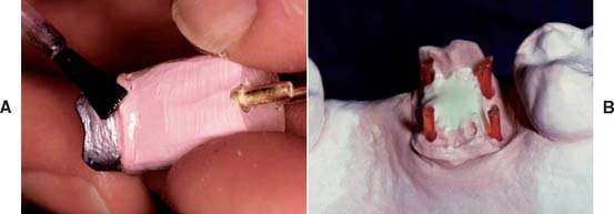
Even a very small undercut on the die of a tooth preparation results in an inability to remove the wax pattern. There may be small dimples in the die (resulting from caries removal or loss of a previous restoration) that are undercut in relation to the path of placement of the new restoration. Normally such areas are blocked out intraorally with glass ionomer or restored with amalgam or another suitable foundation material as part of the mouth preparation phase (see Chapter 6). On occasion, however, blocking them out on the working die may be more practical and convenient, as long as the defect does not extend to within 1 mm of the cavity margin. Zinc phosphate cement is a suitable material (see Chapter 31), but other commercial products (e.g., resin) are available for this purpose (Fig. 18-2).
Provision of Adequate Luting Agent Space
Since the 1920s,2 practitioners have recognized that a space should exist between the internal surface of the casting and the prepared surface of the tooth everywhere except immediately adjacent to the margin. The space provides room for the luting agent (a material that on hardening fills the space and binds the tooth and crown together) and allows complete seating of the restoration during cementation (see Chapters 7 and 31). At the preparation margin, there should be a band of close adaptation (about 1 mm wide) to prevent disintegration and dissolution of the luting agent. The ideal dimension3-5 for the luting agent space has been suggested at 20 to 40 μm for each wall, which implies that a complete crown should have an internal diameter between 40 and 80 μm larger than the diameter of the prepared tooth. Through the use of available techniques in an appropriately standardized manner, such a degree of casting adaptation can routinely be obtained, independent of the geometry of the finish line.6,7
If the luting agent space is too narrow, the casting does not seat properly during cementation because of hydraulic pressure that develops when the viscous mass of luting agent cannot escape through the narrow gap between crown and preparation as the restoration is seated. Conversely, if the luting agent space is too wide, the casting is loose on the tooth, resistance form (see Chapter 7) is reduced, and the position of the casting is difficult to maintain accurately during evaluation and occlusal adjustment. In addition, the risk of the crown loosening during function increases considerably, and its longevity is adversely affected. The precise amount of luting agent space obtained depends on the materials and techniques used in the indirect process, particularly the choice of impression material (see Chapter 14), die material (see Chapter 17), investment (see Chapter 22), and casting alloy (see Chapters 19 and 22 and Fig. 18-1). These factors directly affect the size of the cement space.
Increasing the luting agent space
A number of factors increase the luting agent space for a complete crown:
All other factors remaining equal, each of these factors individually results in an increased distance between the internal surface of the casting and the surface of the prepared tooth. Although the dentist has little control over the polymerization shrinkage of impression materials, die system selection has a direct influence on the size of the wax pattern. With some impression materials, using a multiple-pour system for fabrication of a solid definitive cast and a separate die yields a die that is slightly larger than the prepared tooth. The pattern is, in effect, stretched during manipulation, which results in a proportionally larger internal casting diameter. An internal layer of soft wax is subject to slightly more compression by the setting refractory investment material, leading to a looser fit. Spacers enlarge the die by coating the occlusal surface and vertical axial walls with a thin layer of rapidly drying paint. The expansion of the investment mold can be increased by heating the mold to a slightly higher temperature during the wax elimination phase, and metal can be removed from the internal surface of a cast crown through air abrasion, etching, or milling procedures.
Reduction of the luting agent space
A number of factors reduce the cement space:
Resin and electroplated dies are slightly smaller than stone dies and therefore result in a smaller casting. As alloys cool over a larger temperature range, the additional shrinkage that takes place also results in a smaller casting. There are multiple ways in which to reduce investment expansion. Technique selection, burnout temperature, and water/powder ratio are the most convenient (see Chapter 22). If the investment is mixed with an adjusted water/powder ratio, which results in less setting expansion, the size of the resulting casting is again reduced. When problems routinely surface with castings that are either too loose or too tight, any of the previously mentioned variables may be altered, leading to more predictable results.
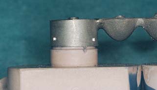
Problems with fitting castings become apparent at two stages of the indirect procedure: when the casting is evaluated on the die and when it is cemented. Recognizing problems at each stage and correcting them before proceeding is crucial. Difficulty with seating the casting on the die is generally caused by wax distortion, the presence of flash extending cervical to the preparation margin (excess wax that was not removed before the investing and casting procedure), improper investment expansion (underexpansion) (Fig. 18-3), or a casting nodule. Modification of the investing and casting protocol solves these problems (see Chapter 22). Consistent problems with castings that do not seat completely when evaluated on the prepared tooth may be corrected by changing just one variable in the protocol. Although many technicians advocate the routine use of die spacer, this is just one of many options to influence the size of the resulting cement space.
Die spacer
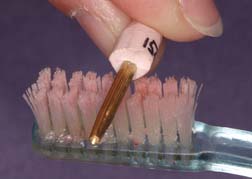
This material (Fig. 18-4) (similar to model airplane paint8) is applied to the die to increase the cement space between axial walls of the prepared tooth and the restoration. It is formulated to maintain constant thickness when painted on the die. However, it should not coat the entire preparation. For adequate marginal adaptation, a band of about 1 mm immediately adjacent to the preparation margin must be left unpainted.9 Thinner is provided to replace the solvent, which tends to evaporate, resulting in an excessive thickness of spacer.
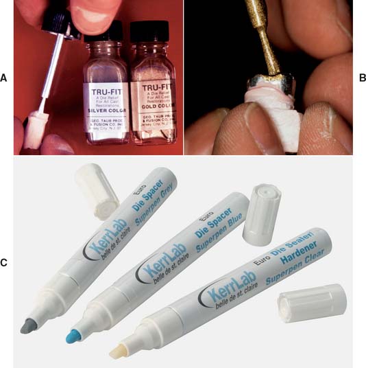
Fig. 18-4 Applying die spacer. A, The material is available in contrasting colors to facilitate applying the required number of coats. B, Care must be taken to keep the material at least 1 mm from the margin. C, Some technicians prefer a pen-application product.
(C, Courtesy of Kerr Lab Corporation, Orange, California.)
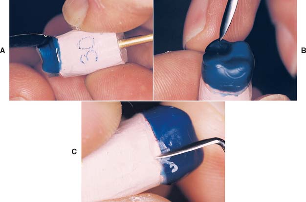
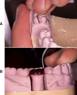
Marking the Margins
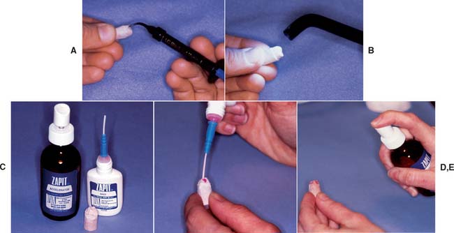
The technician’s awareness of the precise location of the preparation margin is crucial. By marking it with colored pencil, the technician can pinpoint this location (Fig. 18-5). The color should contrast with that of the wax that will be used (e.g., a red pencil can be used for a green wax). An ordinary lead pencil is not recommended, because it can abrade the die, its darker color can interfere with efforts to verify that the wax has been properly adapted at the margin, and traces of the graphite (an antiflux) can prevent complete casting of the margins. The marked margins can be coated with low-viscosity cyanoacrylate resin and immediately blown dry. If performed properly, this procedure adds no more than a micrometer10 to the die. Although removing the excess with acetone is sometimes possible, care must be taken not to create a thick layer of cyanoacrylate, which can result in an unacceptable fit of the final cast restoration. For this reason, higher viscosity resins must be avoided.

MATERIALS SCIENCE
Inlay casting wax (the name given all wax used in forming the pattern for cast restorations) is actually composed of several waxes. Paraffin is usually the main constituent (40% to 60%). The remaining balance consists of dammar resin (to reduce flaking) plus carnauba, ceresin, or candelilla wax (to raise the melting temperature) or beeswax. Sometimes a synthetic wax is substituted for the natural material. Dyes are added to provide color contrasts. Exact formulations are trade secrets, but Coleman11 published the formula for an experimental compound.
The American National Standards Institute (ANSI) and the American Dental Association (ADA)12 have categorized waxes into two types:
Waxes used with direct techniques must not flow appreciably at mouth temperature. Those used with indirect techniques must resist flow at room temperature to maintain their newly shaped forms.
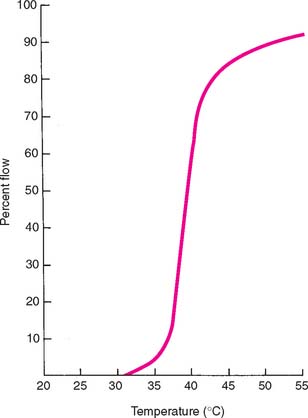
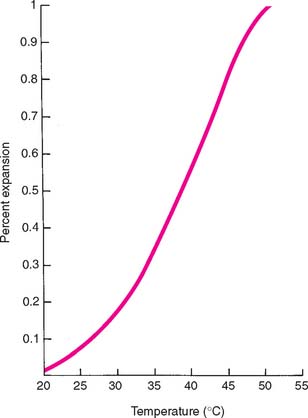
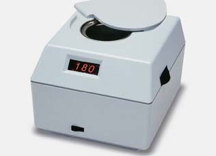
Specifications of the ANSI and ADA govern use of the important properties of residue, flow, and expansion. Because the mold must burn out cleanly to allow the escape of gases and the complete entry of molten alloy, there can be no residual ash. However, the specifications allow a 0.1% residue, which apparently is effectively negligible. Flow requirements, as previously stated, are necessary to control the stability of the wax once it has reached the temperature at which it is carved, burnished, and polished (37° C [99° F] for type I waxes, 25° C [77° F] for type II waxes). In addition, the wax must flow well at typi-cal forming temperatures. Curves of temperature plotted against percentage flow (Fig. 18-6) are furnished by reputable manufacturers and should be consulted when a casting wax is chosen. All waxes expand and contract when heated and cooled, respectively. Manufacturers’ curves of percentage expansion and contraction at various working temperatures (Fig. 18-7) are helpful when methods to use in the investing and casting process are considered. For example, a wax that solidifies at a higher temperature shrinks more and therefore requires more compensation to control fit than does a wax that solidifies at a lower temperature (a reason for not interchanging type I and type II waxes within an established technique). These properties can be adversely affected by repeated heating of the wax, which drives off the more volatile components.13 When waxes are selected for optimal casting accuracy, the use of waxes with different properties for the margin and occlusal portions may be necessary.14 If a casting is to be accurate, the wax pattern must not become significantly distorted. One reason for distortion is that wax has “memory,” which means that it exhibits some elasticity unless it is thoroughly liquefied. This problem can be overcome by applying the initial layer of wax in melted increments or drops. As an alternative, the initial coping can be made by dipping the die into thoroughly melted wax.
However, a serious problem exists when the added wax incorporates strain within the pattern as each increment solidifies. This strain tends to be released with time and subsequently distorts the wax pattern. The rate of wax change is temperature dependent, which means that it increases at higher ambient temperatures. Because wax has a relatively high coefficient of thermal expansion and changes dimension subject to air temperature changes, and because the pattern tends to release its incorporated strain, the margins must be remelted, readapted, and resmoothed immediately before investing. The internal fit of the remelted portion is then closer to the prepared surface of the tooth than is the rest of the casting and therefore may help obtain the necessary space for the luting agent.
TECHNIQUE
A step-by-step waxing technique is recommended. Each step is evaluated before the dentist proceeds to the next, which allows corrections and minimizes extra work. The finished wax patterns should be an accurately shaped anatomic replica of the original teeth. Information needed to shape the restoration correctly is derived from the contours of the unprepared tooth surface, adjacent tooth surfaces, and the opposing occlusal surfaces; however, additional input is needed. This stems from a thorough knowledge of tooth anatomy and the ability to copy three-dimensional structures accurately.
When making a drawing or painting, artists constantly refer to the real-life scene they are trying to reproduce. Similarly, when waxing a restoration, the dentist or technician should refer to a suitable model (e.g., diagnostic casts, unworn extracted teeth, a contralateral tooth) or casts of the unworn natural teeth. It is unwise to copy reproductions of natural teeth (plastic teeth or casts of restored mouths), no matter how skillfully they are made. This would be like an artist trying to render a scene from another artist’s painting, rather than from real life.
Evaluating a three-dimensional shape with accuracy is difficult. The finished wax pattern for a tooth may be too bulbous or too flat. Although it appears “wrong,” pinpointing and correcting the exact problem is a skill achieved only after in-depth study of what constitutes “normal” anatomic form and after learning how to interpret that shape. To evaluate occlusal structure, breaking down the complex surfaces into individual components is helpful. When evaluating axial contours, the practitioner should assess a series of two-dimensional outlines by rotating the wax pattern. These can easily be compared with an appropriate model, and any aberrations can be corrected. It is helpful to recognize that the human eye excels at interpreting even very small differences in height and width of objects (two dimensional), but is not as adept at interpreting similarly subtle differences in depth. Therefore, assessment is facilitated by systematically looking at cross-sections through the pattern and evaluating its silhouette (Fig. 18-8). Rotation of the pattern and repeating this process from all angles of observation speeds up this intricate process.
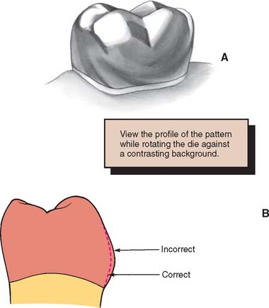
Fig. 18-8 A, Incorrect midfacial contour is difficult to determine by looking directly at a three-dimensional object. B, It is more easily seen by sequential evaluation of the profile of the pattern as it is rotated.
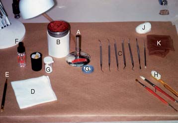
Armamentarium (Fig. 18-9)
Waxing Instruments
Waxing instruments can be categorized by the intent of their design: wax addition, carving, or burnishing. Of the popular PKT instruments (Fig. 18-10A to F) (designed by Dr. Peter K. Thomas specifically for the additive waxing technique), No. 1 and No. 2 are wax addition instruments, No. 3 is a burnisher for refining occlusal anatomy, and Nos. 4 and 5 are wax carvers.
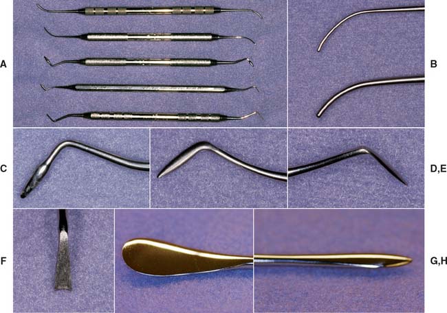
Fig. 18-10 Waxing instruments. A, Top to bottom: PKT Nos. 1 to 5. B, Top to bottom: PKT Nos. 1 and 2. C, PKT No. 3. D and E, PKT No. 4. F, PKT No. 5. G and H, The No. 7 waxing spatula.
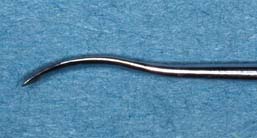
Wax is added by heating the instrument in the Bunsen flame, touching it to the wax, and quickly reheating its shank in the flame. Wax flows away from the hottest part of the instrument, so that if the shank is heated, a bead of wax flows off the tip (Fig. 18-11). However, if the tip is heated, the wax flows up the shank of the instrument (to the considerable annoyance of inexperienced operators). The PKT No. 1 instrument is used for large increments; the smaller No. 2 is used for lesser additions. A No. 7 or 7A waxing spatula (see Fig. 18-10G and H) is useful for adding large amounts of wax, particularly in forming the initial coping (the thimble-like layer of wax that covers all prepared surfaces). Electric waxing instruments (Fig. 18-12) are preferred by some technicians because they allow precise temperature control of the wax, which is important for proper manipulation. Another advantage is that carbon buildup can be kept to a minimum, which easily results from overheating a waxing instrument in a Bunsen flame.
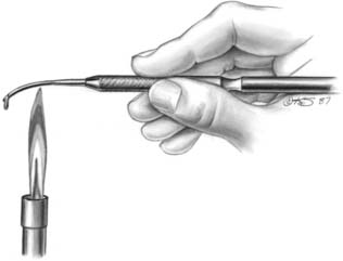
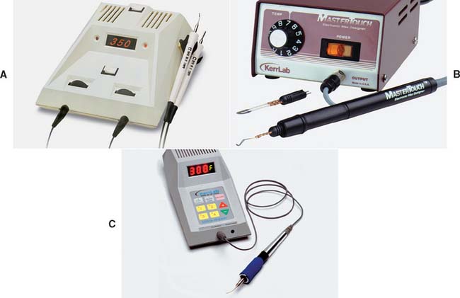
Fig. 18-12 A to C, Electric waxing instruments.
(Courtesy of Kerr Lab Corporation, Orange, California.)
Wax carvers should be kept sharp and should never be heated. In addition to the PKT instruments, the Nos. ½ and 3 Hollenback and the No. 2 Ward carvers (Fig. 18-13) are popular. When carving wax, light pressure should be used to obtain the desired smooth surface.
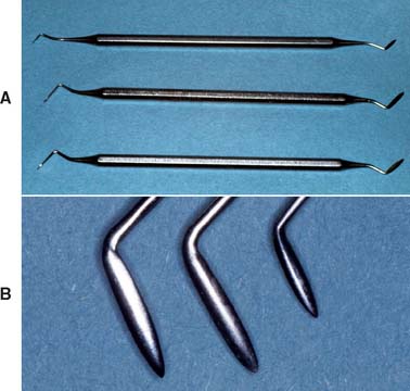
Fig. 18-13 Wax carvers. A, Top to bottom, No. 2 Ward and Nos. ½ and 3 Hollenback. B, Left to right, closer view of these three instruments.
Burnishing is an alternative to carving for obtaining a smooth wax pattern of the desired contour. Burnishing consists of slightly warming a blunt instrument and rubbing the wax. The instrument should not be so hot that it melts the wax surface. The PKT No. 3 instrument is useful for burnishing the occlusal surfaces. The PKT Nos. 1 and 2 can be used for burnishing as well as for wax addition. Another popular burnisher is based on the DPT6 Darby Perry trimmer* (Fig. 18-14).
For removing wax, burnishing is less effective than carving, but it is probably easier to control. It leaves a smoother surface, which can be particularly important when excess wax is trimmed near the margin. Careless (excessive) carving in this area can result in abrasion of the die, resulting in a ledge at the margin of the finished casting.
Posterior Teeth
The following sequence is recommended for waxing posterior teeth:
Internal surface
Forming a closely adapted internal surface is the first step in waxing. The wax must reproduce all retention features of the restoration.
Step-by-step procedure
Wax pattern removal
The wax should be allowed to cool thoroughly before the coping is removed from the die (Fig. 18-18). This is done by maintaining a constant light grip on the pattern by the thumb and forefinger of one hand while applying pressure against them with the thumb and forefinger of the other hand, which also holds the die (see Fig. 18-18B). A small square of washed rubber dam increases friction between the fingers and the pattern. If the pattern fails to move, there may be excess wax beyond the margin, locking the pattern in place.
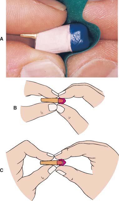
Fig. 18-18 Wax pattern removal. A, A sheet of washed rubber dam increases friction and aids removal. B, The fingers of the left hand hold the die. The right hand holds the pattern. C, The die is pulled from the pattern by bending the fingers of the left hand.
Evaluation
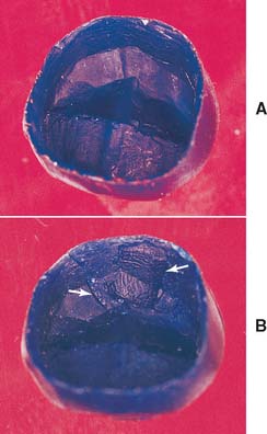
The objective of the first waxing step is a perfectly adapted reproduction of the prepared tooth surfaces. Identifying defects may take some practice. The examiner rotates the pattern under a bright light and looks for shadows formed by folds or creases (Fig. 18-19). A binocular microscope or high-quality magnifying loupe is helpful not only for this step but also throughout the laboratory phase. Ten-power magnification is practical and helpful. Using higher power interferes with maintaining orientation.
Proximal surfaces
The proximal surfaces of natural teeth are not convex (Fig. 18-20). They tend to be flat or slightly concave from the contact area to the cementoenamel junction, and any restoration must reproduce this feature. Overcontouring often makes maintaining good periodontal health difficult, particularly if drifting of teeth has led to increased root proximity.15 Excessively concave or undercontoured proximal surfaces also make flossing ineffective and must be avoided.16
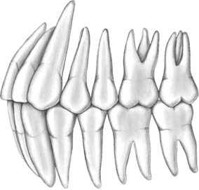
Fig. 18-20 Proximal surfaces gingival to the contact area are normally flat or concave. Note the triangular shape of the posterior embrasures.
Contact areas
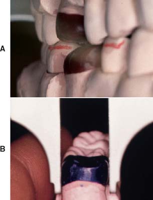
The size and location of the contact areas should be established before the remainder of the proximal surfaces are waxed. Reference is made to contacts between the contralateral teeth and knowledge of anatomic form.
Abnormally large proximal contact areas make plaque control more difficult and can lead to periodontal disease. Very small (point) contacts may be unstable and cause drifting. Deficient contacts can also lead to food impaction; although this is not a direct cause of chronic periodontal disease, it can be very uncomfortable and painful to the patient.
Most posterior contact areas (Fig. 18-21) are located in the occlusal third of the crown. However, contact between the maxillary first and second molar occurs in the middle third.17 The contact areas between mandibular teeth and maxillary molars are generally central. Between maxillary premolars and molars, the contact areas are usually toward the buccal surface (which makes the lingual embrasure larger than the buccal).
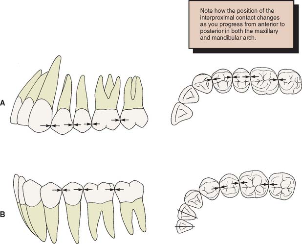
Fig. 18-21 Location of the proximal contact areas. A, On maxillary teeth: progressively more occlusal and buccal the more anterior the tooth. B, On mandibular posterior teeth: central.
Step-by-step procedure
Evaluation
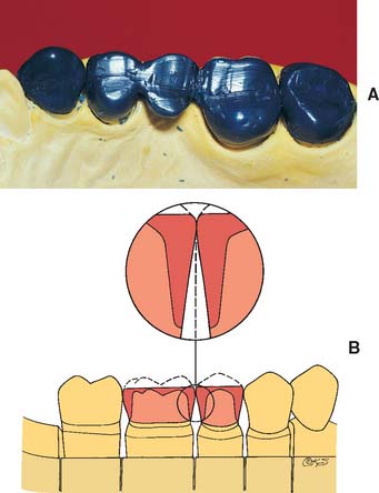
The location of the contact area is checked once again. Where multiple restorations are being made, the proximal embrasure is shaped symmetrically to provide adequate room for the free gingival tissues of adjacent teeth (Fig. 18-24). The proximal surfaces should be flat or slightly concave and should be shaped to eliminate any directional change between the root surface and the finished restoration. The cervical contour of the restoration should be continuous, with the contour of the unprepared tooth structure immediately cervical to the preparation margin.
Axial surfaces
The buccal and lingual surfaces should be shaped to follow the contours of the adjacent teeth. The location of the height of contour (or, alternatively, the survey line for retainers for removable dental prostheses) is particularly important. It is generally located in the gingival third of most teeth, although on mandibular molars it is usually in the middle third of the lingual surface.
Restorations are often made too bulky. Natural teeth are rarely more than 1 mm wider at their height of contour than at the cementoenamel junction. This width should not be exaggerated when a tooth is re-created in wax. The tooth surface gingival to its height of contour immediately adjacent to the gingival soft tissues, sometimes called the emergence profile,18 is usually flat or concave. Creation of a convexity in this area or a shelf or ledge19 makes bacterial plaque removal more difficult and has been shown to cause inflammatory and hyperplastic changes in the marginal gingiva. Before dental plaque was identified as the direct etiologic agent in periodontal disease,20 an excessive axial contour was considered necessary to keep food from entering the gingival sulci.21 However, there is no evidence to support this concept. Indeed, artificially reduced axial contours (as when a prepared tooth is left unprotected for an extended period)22 are associated with healthy gingival tissue. Overcontoured axial surfaces result if there has been insufficient axial reduction during tooth preparation. Special care is needed where bone loss has occurred as a result of periodontal disease, particularly when this has caused exposure of the root near the furcation. The axial contour should then be modified to improve access for plaque removal (Fig. 18-25).

Fig. 18-25 As the cervical margin is placed near root furcations, the axial contour is modified to improve access for plaque control in patients with extensive bone loss. A, Modified wax patterns for a periodontally compromised patient. Note the change in the outline form of the occlusal tables. B, The contralateral teeth have normal axial contour. C to E, Modified contour allows better access for oral hygiene.
Step-by-step procedure
Axial contours
Evaluation
The examiner should evaluate the shape of the tooth at its greatest convexity by looking at the wax pattern and comparing its shapte with that of the contralateral tooth. Each part of the outline should be carefully scrutinized. If the outline is too square or too round, this is modified. The buccal and lingual contours and the embrasures should all be assessed. Initially, assessing individual components rather than the entire contour or outline is helpful. The practitioner should try to relate the shape under evaluation to a “neutral” reference point, such as the midsagittal plane when viewing from the occlusal surface. With more experience, the practitioner will find it easier to review multiple forms simultaneously.
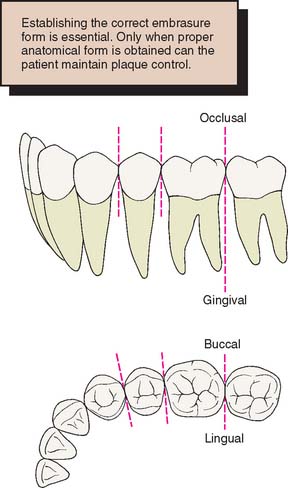
Each contact area has four embrasures: gingival, buccal, lingual, and occlusal. All but the occlusal will have been completed by this stage. The embrasures are normally symmetric about a line drawn through the contact area (Fig. 18-27).
Occlusal surfaces
The cusps and ridges of the occlusal surfaces should be shaped to allow even contact with the opposing teeth while stabilizing the teeth and directing forces along their long axes (see Chapter 4). Nonfunctional cusps (buccal cusps of the maxillary teeth, lingual cusps of the mandibular teeth) should overlap vertically and horizontally, preventing accidental biting of the cheek or tongue and keeping food on the occlusal table.
Point contacts between opposing teeth are preferable to broad, flat occlusal contacts because wear of the restorations is minimized and mastication of tough or fibrous foods is improved. The occlusal surfaces of natural teeth consist of a series of convexities with developmental grooves where the convex ridges meet. The opposing cusps should travel through pathways paralleling these grooves without tooth contact in excursive jaw movements. The occlusal surfaces can be precisely developed with a wax addition technique similar to the one devised by Payne23 that is used in many schools to teach occlusal morphology and function24-26 (Figs. 18-28 and 18-29).
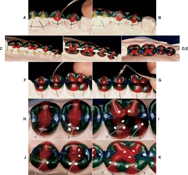
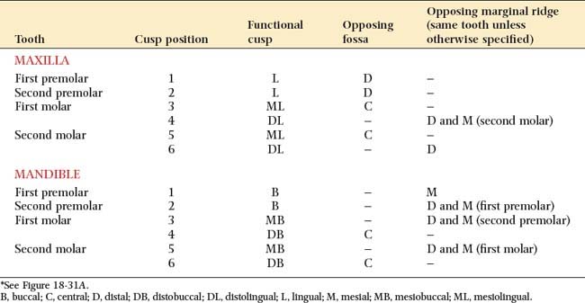
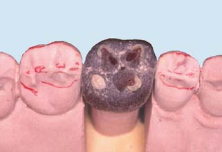
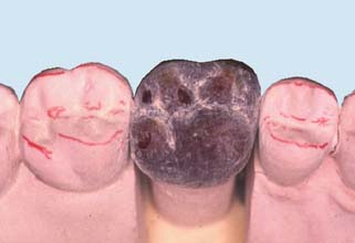
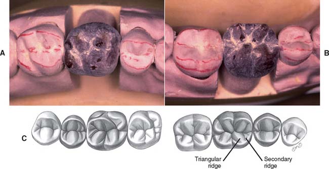
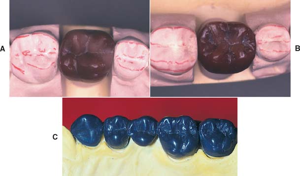
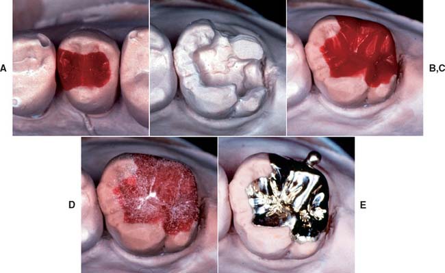
Fig. 18-28 Occlusal waxing with the sequential wax addition technique. A, Accurate occlusal contacts are developed by adding small increments of wax and closing the articulator while the addition is still soft. B, Powder is used to verify the location and size of the contact. C, Cones are used to determine the location of the lingual cusp tips. D and E, The various features of the occlusal surface are developed sequentially in wax. F and G, Secondary occlusal features can be refined by reflowing the wax and burnishing the fissures. H to K, Completed waxing with occlusal contacts marked. (For the cusp–marginal ridge scheme, numbers refer to cusp position in Table 18-1.)
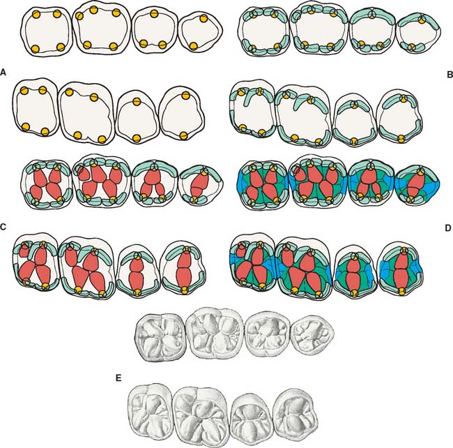
Fig. 18-29 Sequence of occlusal wax addition. A, Step 1: cone placement. B, Step 2: cuspal ridges superimposed. C, Step 3: cones, cuspal ridges, and triangular ridges. D, Step 4: cones, cuspal ridges, triangular ridges, and secondary and marginal ridges. E, Step 5: occlusal waxing complete.
Occlusal scheme
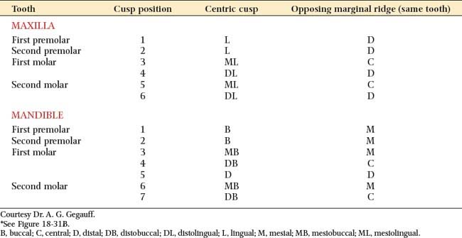
Two occlusal schemes are generally recognized and should be understood when the restorations are planned: cusp–marginal ridge and cusp-fossa (see Chapter 4). In the cusp–marginal ridge scheme, the buccal cusps of the mandibular premolars and the mesiobuccal cusps of the mandibular molars contact the embrasures between the maxillary teeth (i.e., they each contact two teeth). In the cusp-fossa scheme, these mandibular functional cusps contact farther distally into the fossa of the maxillary tooth and contact only one tooth (Tables 18-1 and 18-2). The lingual functional cusps of the maxillary teeth contact the fossae of the mandibular teeth in both schemes.
Most adults with a Class I occlusion and unworn teeth have a cusp–marginal ridge scheme. In natural dentitions, the cusp-fossa arrangement is found only when a slight Class II malocclusion is present. However, for the following reasons, the cusp-fossa arrangement has been recommended over the cusp–marginal ridge when occlusal reconstruction is undertaken:
When the mesiodistal relationships of opposing teeth favor it, the cusp-fossa scheme is optimal. If these relationships are not present, the choice is between (1) distorting coronal axial form to accommodate the preferred occlusal scheme and (2) altering the occlusal structure to accommodate normal axial form. Significant deviation from normal axial form by overcontouring invariably results in periodontal consequences. Altering axial form by undercontouring rarely causes such problems. Depending on the specific spatial relationship between the antagonists, the cusp–marginal ridge scheme may be a better choice in such situations. However, the decision is not always a clear one. Tooth size and position variations among patients produce a continuum between the optimal cusp–marginal ridge and cusp-fossa schemes. Common sense dictates using the scheme that produces the best overall functional and esthetic result. In many cases, this can be determined only by trial and error. The placement of cones before any other occlusal waxing is often the most efficient way to accomplish this.
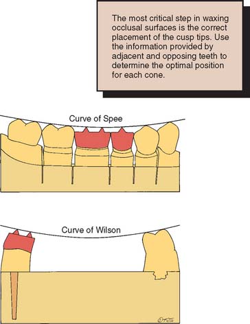
Cusp height and location
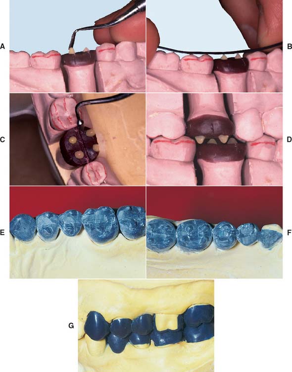
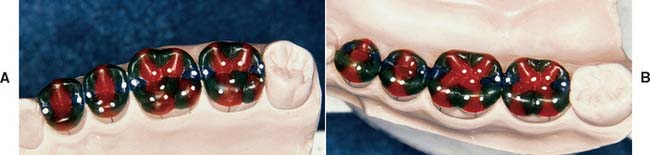
Fig. 18-30 A, Adding wax cones to determine cusp height and location. B, The cusp’s height is determined by the anteroposterior curve (curve of Spee). C, Marking the central fossae of opposing teeth helps position the functional cusps correctly. D, All cones are positioned and tested for interferences in all excursions. E to G, The wax additive technique is especially useful when multiple restorations are provided simultaneously.
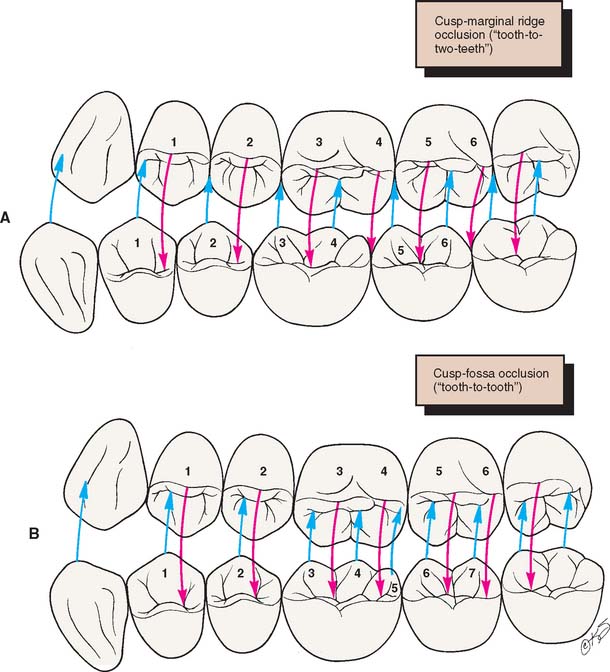
Fig. 18-31 A, Cusp–marginal ridge occlusion. B, Cusp-fossa occlusion. (The numbers refer to those in Tables 18-1 and 18-2.)
Evaluation
The cones should be positioned so they follow the anteroposterior curve (sometimes referred to as the curve of Spee) (Fig. 18-32). This is the anatomic curve established by the occlusal alignment of the teeth, as projected onto the median plane, beginning with the cusp tip of the mandibular canine and following the buccal cusp tips of the premolar and molar teeth, continuing through the anterior border of the mandibular ramus, ending with the most anterior portion of the mandibular condyle. The mandibular cusps should become taller farther distally, and the maxillary cusps should become shorter. They should also follow a mediolateral curve (sometimes referred to as the curve of Wilson). In the mandibular arch, this is the curve (viewed in the frontal plane) that is concave above and contacts the buccal and lingual cusp tips of the mandibular molars; in the maxillary arch, it is the curve (viewed in the frontal plane) that is convex below and contacts the buccal and lingual cusp tips of the maxillary molars. When viewed from the front, the nonfunctional cusps are slightly shorter than the centric cusps. All eccentric movements should be reproduced on the articulator; if unwanted contact results in protrusive, working, and nonworking excursions, they should be eliminated by either reducing or repositioning the cones. Proper cone height and position are key to the development of proper occlusal form.
Completion of axial contours
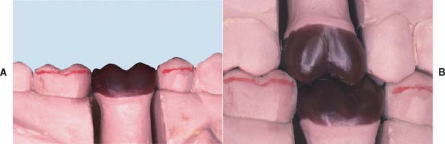
Fig. 18-33 Completed axial contours. A The maxillary buccal cusp ridges. B, At this stage, the buccal surface is complete and should be evaluated for correct contour.
Evaluation
At this stage, the buccal, mesial, lingual, and distal surfaces have been completed (Fig. 18-33). When viewed from these perspectives, the wax pattern should appear identical to an intact tooth. When viewed from the buccal perspective, each cusp should have a distinct profile, with the cusp tip highest and a gentle slope down to the marginal ridges. Adjacent marginal ridges should be of the same height. Occlusal contacts in excursive movements must also be evaluated. If there is unwanted contact, grooves can be created in the cuspal ridges to allow the passage of opposing cusps.
Triangular ridges
Evaluation
The triangular ridges are dusted with zinc stearate or powdered wax (Fig. 18-35; see also Fig. 18-28B). The cusps should still have their correct sharp contour and should not be rounded by improper polishing.
Secondary ridges
Evaluation
If the ridges have been carefully formed, only a small amount of finishing is needed at this stage (Figs. 18-37 and 18-38). Any pits can be filled with wax and the grooves carefully smoothed (see Fig. 18-28G). Initially, obtaining smooth transitions between the occlusal components may be difficult. Smoothing from the grooves onto the individual occlusal features, rather than back and forth, prevents unnecessary accumulations of wax residue in the grooves.
The occlusal surfaces are redusted with zinc stearate or powdered wax, and the occlusal contacts are checked. If a contact has inadvertently been polished away, it can be quickly reformed by adding a drop of wax, closing the articulator to verify that contact was restored, and subsequently reflowing and reshaping the occlusal feature to reestablish a convex contour.
Margin finishing
To optimize the adaptation of the wax pattern (and the cast restoration) to the die, the margins must be reflowed and refinished immediately before investing the wax pattern. The two principal objectives are (1) minimizing dissolution of the luting agent and (2) facilitating plaque control.
If a zone of superior adaptation (i.e., minimum marginal gap width) between the casting and the prepared tooth surface is created, cement dissolution is reduced.27 To obtain this superior adaptation, the pattern should be reflowed over a band approximately 1 mm wide, measured from the margin onto the prepared surface (Fig. 18-39).
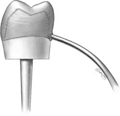
Fig. 18-39 Reflowing the margins. The objective is to create a well-adapted, 1-mm zone to prevent cement dissolution.
Plaque control is facilitated by producing cast restorations that exhibit a smooth transition from restoration to tooth without any sudden directional change. In addition, the axial surface of the restoration must be highly polished (see Chapter 29). Because the use of any metal polishing compound or abrasive results in removal of material, metal finishing procedures should be kept to a minimum near the margin. The best way to prepare for this step is to ensure superior smoothness of the wax pattern when the reflowing process is complete. This should be verified under magnification with loupes or a binocular microscope.
Step-by-step procedure
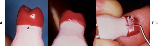
Fig. 18-40 Reflowing margins. A, After waxing, a marginal discrepancy is normally apparent (arrow). This must be corrected before investing. B, Use a large, well-heated instrument to melt completely through the wax. Then continue around the preparation margin; then add wax to fill the depression. C, When the pattern has cooled, carefully trim or burnish the marginal excess.
The wax pattern is removed from the die without distortion and may be replaced for final evaluation before investing. However, if the pattern is not repositioned in exactly the same direction as that in which it was removed, reburnishing of the margins may be necessary.
Evaluation
Being thorough at this stage will pay dividends later. Because of the wax pattern’s color and glossy surface, small defects can be difficult to identify. If they are not noticed, a later remake may be necessary.
Avoid overwaxing. Very little finishing of a cast metal margin is possible without damaging the die. Any flash of wax that extends beyond the finish line must be trimmed at this stage. Otherwise, it will cause distortion as the pattern is removed, or it will prevent the cast metal restoration from completely seating. A gap between the wax and the die, resulting in an open margin, can be difficult to detect. The die should be oriented so that the observer’s line of sight is precisely along the wax-die interface. If the wax is not well adapted, a black shadow line will be visible. This is hard to see in wax but easier to see (but too late) in metal. A binocular microscope or loupe is very helpful for this stage (Fig. 18-41). To ensure that new debris has not accumulated during the finishing procedures, a final evaluation of the occlusal and axial surfaces is performed. The pattern is now ready for investing (see Chapter 22).
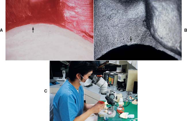
Fig. 18-41 Evaluation. Defects must be identified and corrected before investing. A, Marginal excess or flash (arrow) is difficult to see in wax but must be carefully removed. B, A small defect (arrow) is easier to see in the metal but harder to correct. C, Magnification is the most practical way to finish margins properly.
Waxing inlays and onlays
The sequence of steps for fabricating a wax pattern for an inlay or onlay is similar to that for a complete crown, although the unprepared tooth can often serve as a guide to axial and occlusal contour (Fig. 18-42). Sometimes manipulation of a small inlay can be difficult. One approach is to embed a loop of floss into the pattern for easier removal.
Anterior Teeth
The approach to waxing anterior teeth is slightly different than the approach to waxing posterior teeth. Anatomic contour waxing is recommended for metal-ceramic restorations, because there is better control over the thickness of porcelain and the smoothness of the metal-ceramic junction. When several anterior teeth are to be restored, a guide to the lingual and labial contours is essential (Fig. 18-43). The contour of the palatal and incisal surfaces significantly influences the articulation. They are most effectively recreated by using a custom anterior guide table (see Chapter 2). This can be made from diagnostic casts (if their initial form was satisfactory) or from a diagnostic waxing or cast made from an impression of interim restorations. The latter can be used when the interim restorations resulted in clinically satisfactory function and appearance. The shape of the anterior teeth affects the patient’s speech, lip support, and appearance. They should be determined carefully and with as many diagnostic aids as necessary.
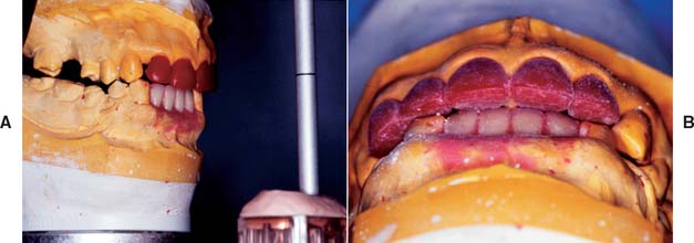
Fig. 18-43 A and B, Optimum contours for anterior restorations are developed with the aid of a custom anterior guide table (see Fig. 19-5).
Lingual and incisal surfaces
The position of the incisal edges is determined by the overall arch form of the anterior teeth and the functional occlusal requirements (Fig. 18-44). As with waxing of posterior occlusal surfaces, cones can be used to initially delineate the approximate position of the incisal edge. Additional wax can then be applied as necessary.
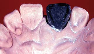
Fig. 18-44 When the lingual surface of an anterior tooth is waxed, the contralateral tooth should be used as a guide.
Opposing incisors should contact evenly during protrusive movements but not during lateral excursions. This is achieved by making a concavity in the lingual surface of maxillary incisors. The ability to make this concavity smooth is very important. As a result, the patient is given a smooth envelope of motion, and potential neuromuscular disturbances are avoided. In maximum intercuspation, anterior teeth ideally should be just out of contact. Mylar shim stock should just “drag” between the patterns. The lingual surfaces of mandibular incisors and canines are noncontacting surfaces. Nevertheless, they should be shaped for easy plaque control. They should not be overcontoured.
Labial surfaces
The shape of the labial surfaces, particularly the location of the mesiolabial and distolabial line angles, determines the appearance of anterior teeth (Fig. 18-45). If the labial surface is too bulbous, plaque control may be difficult, and there may be lingual tilting of the tooth caused by the force exerted by the upper lip. When individual anterior teeth are waxed, careful study of the embrasure form of adjacent teeth can be particularly helpful.
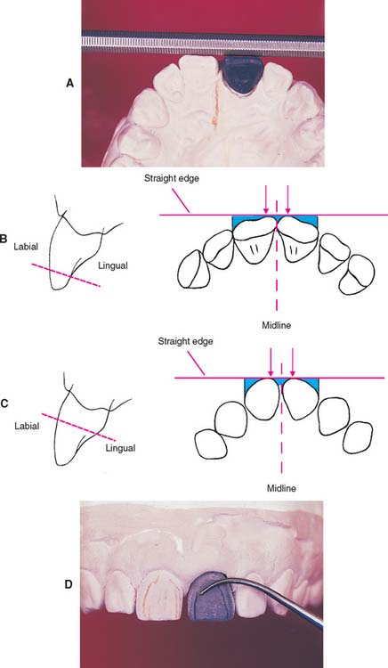
Fig. 18-45 Waxing the labial surfaces of maxillary incisors. Typically, the two central incisors should possess mirror symmetry around the midline. A, As the waxing progresses, symmetry can be judged by placing a straight edge near the incisal edge and exactly perpendicular to the palatal midline. B, The straight edge should contact each central incisor at precisely the same distance from the midline (arrows). The wax can be easily adjusted if proper contact does not occur. Then the spaces between the straight edge and the wax pattern (blue areas) are evaluated. The left and right teeth should be mirror images both mesially and distally. C, The straight edge is repositioned farther apically, and the analysis is repeated. Note how the form of the embrasures varies at the different locations. D, Dusting the wax pattern and marking the mesial and distal line angles. These should correspond to the line angles marked on the contralateral tooth.
Wax Cut-Back
If a ceramic veneer is to be used, once the final contour of the wax pattern has been completed, the pattern is cut back over an even thickness—usually about 1 mm—to provide room for the porcelain fused onto the cast metal substructure (Fig. 18-46). The design and technique are discussed in Chapter 19.
Waxing Connectors
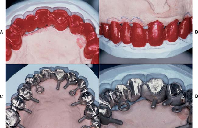
The connectors that join the separate components of a fixed dental prosthesis are created in wax just before the margins are finalized (Fig. 18-47). Whether the connectors are cast or soldered, they must be shaped in wax so that their size, position, and configuration are controlled precisely. Connector size is important primarily from a mechanical perspective. To ensure optimal strength, the connector should be as large as possible. However, from a biologic perspective, connectors should not impinge on the gingival tissues and should be at least 1 mm above the crest of the interproximal soft tissue. Embrasure form gingival to the connectors must enable optimal plaque control. The cervical aspect of the connector must be shaped to a smooth archlike configuration. In esthetic areas (i.e., anterior fixed dental prostheses), connectors should be hidden behind the esthetic ceramic veneer. Therefore, connectors are often placed slightly lingually when connectors are waxed for anterior prostheses (Fig. 18-48). Connector form and design are discussed in detail in Chapter 28.
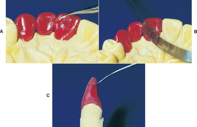
Fig. 18-47 Waxing connectors. A, The shape, size, and location of connectors can be controlled by forming them in wax. B, A ribbon saw is then used to section them. C, The correct cross-sectional configuration of an anterior connector.
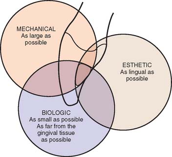
Fig. 18-48 Considerations for anterior connector placement. Mechanically, the connector should be as large as possible for strength. From a biologic perspective, the connector is most effectively placed in the incisal half of the proximal wall. For esthetics, the connector should be placed in the lingual (palatal) half of the proximal wall.
REVIEW OF TECHNIQUE
Figure 18-49 summarizes the steps for waxing to anatomic form.
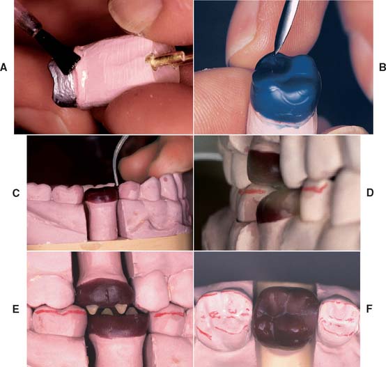
Fig. 18-49 Technique review. A, The die is modified as necessary and lubricated. B, An initial coping is waxed, forming the internal surface. C, The proximal surfaces are developed, with correctly located contact areas. D, The axial surfaces are waxed. E, The occlusal surfaces are developed with a wax addition technique. F, The margins are reflowed, and the wax pattern is finished.
SUMMARY
If the waxing procedure is followed in a sequential order, inexperienced but conscientious operators should have no problem achieving excellent results. With more experience, they can combine and modify some of these steps; however, waxing up teeth “from memory” is not advised. Even the most experienced technician should copy the shape of natural teeth rather than redesign them.
 GLOSSARY*
adaptation \ăd′ăp-tā′shun\ n (1610): 1: the act or process of adapting; the state of being adapted 2: the act of purposefully adapting two surfaces to provide intimate contact 3: the progressive adjustive changes in sensitivity that regularly accompany continuous sensory stimulation or lack of stimulation 4: in dentistry, (a) the degree of fit between a prosthesis and supporting structures, (b) the degree of proximity of a restorative material to a tooth preparation, (c) the adjustment of orthodontic bands to teeth
anatomic crown \ăn′a-t m′
m′ k kroun\: the portion of a natural tooth that extends coronal from the cementoenamel junction—called also anatomical crown
an·tag·on·ist \ăn-tăg′a-nst\ n (1599): 1: a tooth in one jaw that articulates with a tooth in the other jaw—called also dental antagonist 2: a substance that tends to nullify the actions of another, as a drug that binds to cell receptors without eliciting a biologic response 3: a muscle whose action is the direct opposite of another muscle
anteroposterior curve \ăn-ter-o-p-stîr′ē-or kûrv\: the anatomic curve established by the occlusal alignment of the teeth, as projected onto the median plane, beginning with the cusp tip of the mandibular canine and following the buccal cusp tips of the premolar and molar teeth, continuing through the anterior border of the mandibular ramus, ending with the anterior most portion of the mandibular condyle. First described by Ferdinand Graf Spee, German anatomist, in 1890—see CURVE OF SPEE
bees’ wax \bēz wăks′\ n (1676): a low-melting wax obtained from honeycomb and used as an ingredient of many dental impression waxes
Bonwill triangle \Bn′wl trī′ăng′gl\ [William Gibson Arlington Bonwill, American dentist, 1833–1899]: eponym for a 4 inch equilateral triangle bounded by lines connecting the contact points of the mandibular central incisor’s incisal edge (or the mid-line of the mandibular residual ridge) to each condyle (usually its mid point) and from one condyle to the other, first described by Bonwill in 1858 while introducing his Anatomical Articulator
casting wax \kăs′tng wăks\: a composition containing various waxes with desired properties for making wax patterns to be formed into metal castings
centric stop \s n′trk stp\: opposing cuspal/fossae contacts that maintain the occlusal vertical dimension between the opposing arches
curve of Monson \kûrv ŭv Mn-son\ [George S. Monson, St. Paul, Minnesota, U.S. dentist, 1869–1933]: eponym for a proposed ideal curve of occlusion in which each cusp and incisal edge touches or conforms to a segment of the surface of a sphere 8 inches in diameter with its center in the region of the glabella
Monson GS. Occlusion as applied to crown and bridgework. J Nat Dent Assoc 1920;7:399–417.
Monson GS. Some important factors which influence occlusion. J Nat Dent Assoc 1922;9:498–503.
curve of occlusion \kûrv ŭv a-klōō′shun\: the average curve established by the incisal edges and occlusal surfaces of the anterior and posterior teeth in either arch
curve of Spee [Ferdinand Graf Spee, Prosector of Anatomy, Kiel, Germany, 1855–1937]: eponym for ANTEROPOSTERIOR CURVE
Spee FG. Die Verschiebrangsbahn des Unterkiefers am Schadell. Arch Anat Physiol (Leipz) 1890;16:285–94.
curve of Wilson [George H. Wilson, Cleveland, Ohio, U.S. dentist, 1855–1922]: 1: eponym for the MEDIOLATERAL CURVE 2: in the theory that occlusion should be spherical, the curvature of the cusps as projected on the frontal plane expressed in both arches; the curve in the lower arch being concave and the one in the upper arch being convex. The curvature in the lower arch is affected by an equal lingual inclination of the right and left molars so that the tip points of the corresponding cross-aligned cusps can be placed into the circumferences of a circle. The transverse cuspal curvature of the upper teeth is affected by the equal buccal inclinations of their long axes
Wilson GH. A manual of dental prosthetics. Philadelphia Lea & Febiger, 1911:22–37.
cusp angle \kŭsp ăng′gal\: the angle made by the average slope of a cusp with the cusp plane measured mesiodistal or buccolingually
cusp-fossa articulation scheme: an occlusal arrangement where the maxillary and mandibular centric cusps articulate with the opposing fossae in maximum intercuspation
cusp height \kŭsp hīt\: the perpendicular distance between the tip of a cusp and its base plane
cusp-marginal ridge articulation scheme: an occlusal arrangement where the mandibular second premolar buccal cusp and mandibular molar mesiobuccal cusps articulate with the opposing occlusal embrasures in maximum intercuspation
cusp plane \kŭsp plān\: the plane determined by the two buccal cusp tips and the highest lingual cusp of a molar
cusp plane angle \kŭsp plān ăng′gal\: the incline of the cusp plane in relation to the plane of occlusion
die spacer \dī spās′er\: an agent applied to a die to provide space for the luting agent in the finished casting
em·bra·sure \m-brā′zher\ n (1702): l: the space formed when adjacent surfaces flair away from one another 2: in dentistry, the space defined by surfaces of two adjacent teeth; there are four embrasure spaces associated with each proximal contact area: occlusal/incisal, mesial, distal, and gingival
emergence profile \-mûr′jens prō′fīl\: the contour of a tooth or restoration, such as a crown on a natural tooth or dental implant abutment, as it relates to the adjacent tissues
fossa \fōs′a\ n, pl fossae \fōs′ē′\ (1771): an anatomical pit, groove, or depression
height of contour \hīt ŭv kn′t
r′\: a line encircling a tooth and designating its greatest circumference at a selected axial position determined by a dental surveyor; a line encircling a body designating its greatest circumference in a specified plane
intercuspal contact \n′ter-kŭs′păl kn′tăkt\: the contact between the cusps of opposing teeth
interproximal contact \n′ter-prk′sa-mal kn′tăkt\: the area of a tooth that is in close association, connection, or touch with an adjacent tooth in the same arch
lobe \lōb\ n (1525): a curved or rounded projection or division, especially of a body organ or part
luting agent: any material used to attach or cement indirect restorations to prepared teeth
marginal ridge \mär′ja-nal rj\: a component of the tooth structure forming the occlusal proximal margin of a premolar or molar
mediolateral curve \mē′dē-ō-lăt′ar-al kûrv\: in the mandibular arch, that curve (viewed in the frontal plane) which is concave above and contacts the buccal and lingual cusp tips of the mandibular molars; in the maxillary arch, that curve (viewed in the frontal plane) which is convex below and contacts the buccal and lingual cusp tips of the maxillary molars
oblique ridge \ō-blēk′, a-blēk′ rj\: the elevation in the enamel that runs obliquely across the occlusal surface of a maxillary molar
occlusal embrasure \a-klōō′zal, -sal m-brā′zhar\: the interdental space that is coronal to the contact area
occlusal pattern \a-klōō′zal, -sal păt′arn\: the form or design of the masticatory surfaces of a tooth or teeth based on natural or modified anatomic or nonanatomic teeth
occlusal plane \a-klōō′zal, -sal plān\: 1: the average plane established by the incisal and occlusal surfaces of the teeth. Generally, it is not a plane but represents the planar mean of the curvature of these surfaces 2: the surface of wax occlusion rims contoured to guide in the arrangement of denture teeth 3: a flat metallic plate used in arranging denture teeth—comp to CURVE OF OCCLUSION
occlusal surface \a-klōō′zal, -sal sûr′fas\ obs: a surface of a posterior tooth or occlusion rim that is intended to make contact with an opposing occlusal surface (GPT-1)
occlusal table \a-klōō′zal, -sal tā′bal\: the portion of the occlusal surfaces of posterior teeth that lies within the perimeter of the cusp tips and marginal ridges; the functional portion(s) of the occlusal surface(s) of a posterior tooth (teeth)
pat·tern \păt′urn\ n (14c): a form that is used to make a mold; a model for making a mold—see OCCLUSAL P.
plane \plān\ n (1570): a flat surface defined by three points—see AXIS ORBITAL P., CAMPER’s P., CORONAL P., CUSP P., FRANKFORT HORIZONTAL P., FRONTAL P., HORIZONTAL P., INCLINED P., MANDIBULAR P., MEDIAN P., OCCLUSAL P., SAGITTAL P.
separating medium \sp′a-rāt′ng mē′dē-am\: 1: a coating applied to a surface and serving to prevent a second surface from adhering to the first 2: a material, usually applied on an impression, to facilitate removal of the cast
supporting cusps \sa-pôrt′ng kŭsps\: those cusps or incisal edges of teeth that contact in and support maximum intercuspation. Usually facial cusps of the mandibular posterior teeth, the maxillary palatal cusps, and the incisal edges of the mandibular anterior teeth
tri·pod·i·za·tion \trp′a-d-zā′shun\ n: an occlusal scheme characterized by a cusp to fossa relationship in which there are three points of contact about the cusp and opposing fossa with no contact on the cusp tip
wax \wăks\ n (bef. 12c): one of several esters of fatty acids with higher alcohols, usually monohydric alcohols. Dental waxes are combinations of various types of waxes compounded to provide desired physical properties—see BASEPLATE W., BOXING W., CASTING W., DENTAL IMPRESSION W., MODELING W.
wax expansion \wăks k-spăn′shun\: a method of expanding a wax pattern to compensate for the shrinkage of gold during the casting process
wax pattern \wăks păt′urn\: a wax form that is the positive likeness of an object to be fabricated
wax·ing \wăks′ng\ v obs: the contouring of a wax pattern or the wax base of a trial denture into the desired form (GPT-1)
STUDY QUESTIONS
1 Frankfort H. The Art and Architecture of the Ancient Orient. Harmondsworth-Middlesex, UK: Penguin Books, 1956;26 ff.
2 Black GV. The technical procedures in filling teeth. Operative Dentistry, vol 2. New York: Medico-Dental Publishing. 1924.
3 Cherberg JW, Nicholls JI. Analysis of gold removal by acid etching and electrochemical stripping. J Prosthet Dent. 1979;42:638. (Quoting BJ Parkins: The effect of electropolishing on the unprotected margins of gold castings. Thesis, Northwestern University, 1969.)
4 Fusayama T, et al. Relief of resistance of cement of full cast crowns. J Prosthet Dent. 1964;14:95.
5 Eames WB, et al. Techniques to improve the seating of castings. J Am Dent Assoc. 1978;96:432.
6 Byrne G. Influence of finish-line form on crown cementation. Int J Prosthodont. 1992;5:137.
7 Syu JZ, et al. Influence of finish-line geometry on the fit of crowns. Int J Prosthodont. 1993;1:25.
8 Campagni WV, et al. Measurement of paint-on die spacers used for casting relief. J Prosthet Dent. 1982;47:606.
9 Emtiaz S, Goldstein G. Effect of die spacers on precementation space of complete-coverage restorations. Int J Prosthodont. 1997;10:131.
10 Fukui H, et al. Effectiveness of hardening films on die stone. J Prosthet Dent. 1980;44:57.
11 Coleman RL. Physical properties of dental materials [U.S. Bureau of Standards research paper 32]. J Res Natl Bur Stand. 1928;1:867.
12 Council on Dental Materials, Instruments, and Equipment. Revised ANSI/ADA specification No. 4 for inlay wax. J Am Dent Assoc. 1984;108:88.
13 Kotsiomiti E, McCabe JF. Stability of dental waxes following repeated heatings. J Oral Rehabil. 1995;22:135.
14 Ito M, et al. Effect of selected physical properties of waxes on investments and casting shrinkage. J Prosthet Dent. 1996;75:211.
15 Jameson LM, Malone WFP. Crown contours and gingival response. J Prosthet Dent. 1982;47:620.
16 Burch JG. Ten rules for developing crown contours in restorations. Dent Clin North Am. 1971;15:611.
17 Burch JG, Miller JB. Evaluating crown contours of a wax pattern. J Prosthet Dent. 1973;30:454.
18 Stein RS, Kuwata M. A dentist and a dental technologist analyze current ceramo-metal procedures. Dent Clin North Am. 1977;21:729.
19 Perel ML. Axial crown contours. J Prosthet Dent. 1971;25:642.
20 Löe H, et al. Experimental gingivitis in man. J Periodontol. 1965;36:177.
21 Wheeler RC. Complete crown form and the periodontium. J Prosthet Dent. 1961;11:722.
22 Herlands RE, et al. Forms, contours, and extensions of full coverage restorations in occlusal reconstruction. Dent Clin North Am. 1962;6:147.
23 Payne EV. Functional occlusal wax-up. In: Eissmann HF, et al, editors. Dental Laboratory Procedures, vol 2: Fixed Partial Dentures. St. Louis: Mosby, 1980.
24 Lundeen HC. Introduction to Occlusal Anatomy. Lexington: University of Kentucky Press, 1969.
25 Thomas PK. Syllabus on Full-Mouth Waxing Technique for Rehabilitation. San Diego: Instant Printing Service, 1967.
26 Shillingburg HT, et al. Guide to Occlusal Waxing, 2nd ed. Chicago: Quintessence Publishing, 1984.
27 Jacobs MS, Windeler AS. An investigation of dental luting cement solubility as a function of the marginal gap. J Prosthet Dent. 1991;65:436.
28 Monson GS. Occlusion as applied to crown and bridgework. J Natl Dent Assoc. 1920;7:399.
29 Monson GS. Some important factors which influence occlusion. J Natl Dent Assoc. 1922;9:498.
30 Spee FG. Die Verschiebrangsbahn des Unterkiefers am Schadell. Arch Anat Physiol (Leipz). 1890;16:285.
31 Wilson GH. A Manual of Dental Prosthetics. Philadelphia: Lea & Febiger, 1911;22-37.