13 IMPLANT-SUPPORTED FIXED PROSTHESES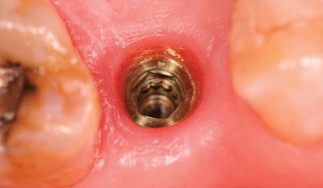
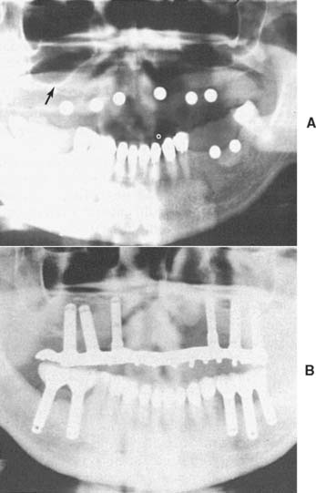
Today the continued high rate of success achieved with osseous integrated dental implants allows a greater number of patients to enjoy the benefits of fixed rather than removable dental prostheses.1-3 The main indications for implant-supported restorations in the partially edentulous patient are the free-end distal extension, in which no posterior abutment is available (Fig. 13-1), and the long edentulous span. In both these situations, the conventional dental treatment plan would include a partial removable dental prosthesis. However, with the advent of dental implants, the patient can benefit from fixed restorations. In addition, in the short edentulous span, the single dental implant is a popular option (Fig. 13-2).
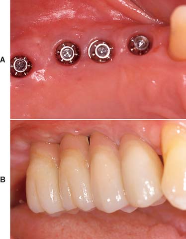
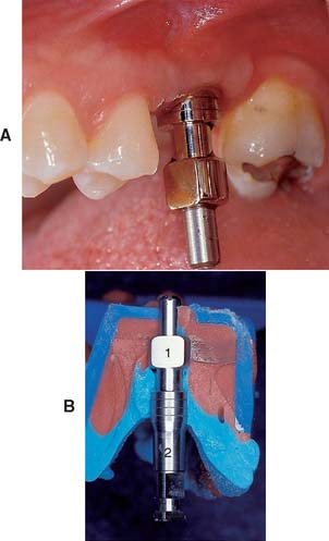
Fig. 13-1 Implant-supported fixed prosthesis. Four dental implants (A) supporting a fixed dental prosthesis (B).
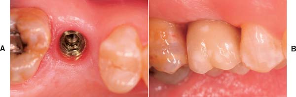
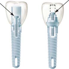
Fig. 13-2 A, Single-tooth implant with an internal anti-rotational feature. B, Implant crown replacing a single missing tooth (cement retained).
IMPLANT TYPES
There are three major subgroups of dental implants: subperiosteal, transosteal, and endosteal (Fig. 13-3). The first two, subperiosteal and transosteal, are designed primarily to anchor dentures in the completely edentulous patient, and thus they are outside the scope of this chapter. The third, endosteal dental implants, are surgically placed within alveolar or basal bone and are most commonly used for the treatment of partially edentulous patients, either singly or in multiples. They can be further subdivided by shape into blade form (plate form) and root form. Blades are wedge-shaped or rectangular in cross-section and are generally 2.5 mm wide, 8 to 15 mm deep, and 15 to 30 mm long. Root forms are 3 to 6 mm in diameter and 8 to 20 mm long, often with external threads (Fig. 13-4). Endosteal dental implants are also categorized as one-stage or two-stage. The one-stage dental implant is designed to be placed in the bone and to immediately project through mucosa into the oral cavity. The two-stage dental implant requires two surgical procedures. First, the implant is placed in bone to the level of the cortical plate and the oral mucosa is sutured over it; this is left for a prescribed healing period (usually 3 months in the mandible and 6 months in the maxilla), depending on the quality of bone. Then, in a second surgery, the mucosa is reflected from the superior surface of the implant, and an extension collar or abutment that projects into the oral cavity is fastened to the implant. Some authors have suggested shortening the time before implant loading, but the long-term consequences of this are still being investigated.4,5
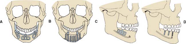
Fig. 13-3 The three major subgroups of dental implants. A, Subperiosteal. B, Transosteal. C and D, Endosteal. Endosteal implants can be further subdivided into plate form (C) and root form (D).
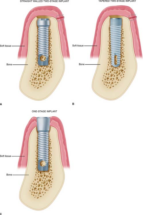
Plate Implants (Blades)
Blades were the first endosteal dental implant to be used with reasonable success in a large number of patients. In all the original studies on blades, the researchers used one-stage systems, but the success rates were considerably lower than those of current root-form implants. It has been suggested6 that many of the problems of blade implants can be traced to the high temperature at which the bone sites were prepared and the routine immediate loading of this type of implant. Both these practices have been linked to the fibrous encapsulation that occurred with many of the original blade implants. Consequently, submersible titanium blades are now available, and in more recent blade studies,7 investigators have reported success rates above 80% for 5 years. However, the drawbacks to blade implants remain: difficulty of preparing precision slots for blade placement in comparison with placing holes accurately for root-form implants and the disastrously large circumferential area of the jaw that can be affected when a blade fails.
Root-Form Implants
Root-form endosteal dental implants are considered to be state-of-the-art implant dentistry. Advantages include adaptability to multiple intraoral locations, uniformly precise implant site preparation, and comparatively low adverse consequences similar to those experienced when a tooth is lost. Most root forms are made of titanium or titanium alloy with or without hydroxyapatite coating; these materials are perceived to have the highest biofunctionality. Both threaded and nonthreaded designs are available and are quite popular. Today many of the titanium implants are grit blasted or acid etched to roughen the surface and increase the area for bone contact. Even the theaded dental implants can be further subdivided into “straight” and “tapered” (see Fig. 13-4).
In the National Institutes of Health (NIH) Consensus Conference1 in 1988, root-form implants were reported to have already constituted 78% of the dental implant market. This trend is credited to the Brånemark system, which set the precedent for surgical techniques and restorative procedures that result in predictably successful implants. Two of the most important additions from the Swedish research team, led by P. I. Brånemark, were atraumatic implant placement and delayed implant loading. These factors contributed to a remarkably increased degree of implant predictability. The original Brånemark success rate of 91% in the mandible over 15 years2 has become the standard against which other implant systems are judged.8 Many of the other root-form implant systems are also believed to have reached or exceeded this high level of long-term success.
TREATMENT PLANNING FOR THE IMPLANT PATIENT
Implant success reported from major research institutions is quite high. However, meticulous attention to the procedures of patient selection, diagnosis, and treatment planning is necessary to duplicate this success. Indications for dental implant treatment in the partially edentulous patient are provided in Box 13-1.
A combined surgical and restorative treatment plan must be devised for prospective implant recipients. Feasible nonimplant alternatives should be included in the overall treatment discussions. Patients need to be evaluated preoperatively and assessed if they will be able to tolerate the procedure. The predictable risks and expected benefits should be weighed for each person. Although the placement of dental implants does entail some risks, they are relatively minor. Absolute contraindications, based on immediate surgical and anesthetic risks, are limited to individuals who are acutely ill, individuals with uncontrolled metabolic disease, and pregnant women (these contraindications apply to virtually all elective surgical procedures).
Local and systemic contraindications that threaten long-term implant retention must also be evaluated. Implants may be contraindicated in patients with abnormal bone metabolism, poor oral hygiene, and previous irradiation of the implant site. Most potential implant placement patients became edentulous or partially edentulous from caries or periodontal disease resulting from poor oral hygiene. Suspicion that inadequate hygiene will continue is a relative contraindication to implant placement. Patients must be motivated and educated in oral hygiene techniques as part of their preparation for implants. Some individuals, such as those suffering from paralysis of the arms, debilitating arthritis, cerebral palsy, and severe mental retardation, may not be able to improve their hygiene. Implants are contraindicated in these patients unless adequate oral hygiene will be provided by caregivers. A summary of contraindications to implant placement is presented in Box 13-2.
Box 13-2 Contraindications to Implant Placement (National Institutes of Health Consensus Conference)
Clinical Evaluation
Evaluation of the planned implant site begins with a thorough clinical examination. This examination determines whether there is adequate bone and identifies anatomic structures that could interfere with ideal implant placement. Visual inspection and palpation allow the detection of flabby excess tissue, bony ridges, and sharp underlying osseous formations and undercuts that would limit implant insertion. However, clinical inspection alone may not be adequate if there is thick overlying soft tissue that is dense, immobile, and fibrous.
Radiographic Evaluation
Radiographic evaluation is also necessary. The best initial film is the panoramic view. However, there can be variations in magnification (5% to 35%); a small radiopaque reference object should therefore be placed near the proposed implant placement site during the exposure (Fig. 13-5). Measurement of this image on the actual radiograph enables the practitioner to correct for any magnification error (Fig. 13-6). A ball bearing placed in wax on a denture baseplate or in polyvinyl siloxane impression putty works well. Some new panoramic radiography machines have standardized enlargement ratios, which makes correction markers less necessary.
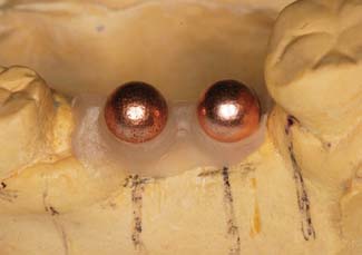
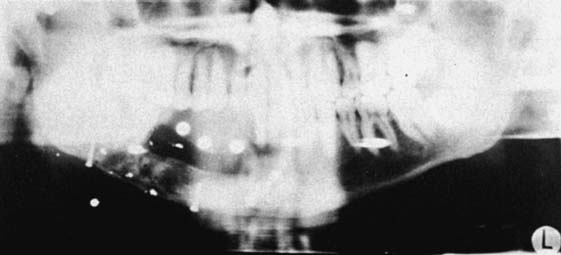
Fig. 13-6 A panoramic radiograph exposed with the ball bearings positioned intraorally with a wax or resin baseplate.
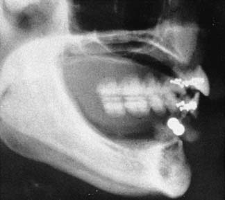
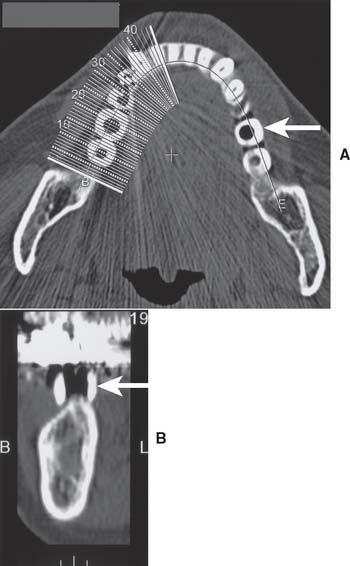
The widths of the posterior mandible and maxilla are determined primarily by clinical examination. Bone width not revealed on a panoramic film can be evaluated in the anterior maxilla and mandible with a cephalometric film (Fig. 13-7). The location of the inferior alveolar canal and maxillary sinus can be determined by specialized computed tomography (CT) scans (Fig. 13-8), although high radiation exposure and considerable expense may limit their routine use. However, significant advances being made in this technology may change this trend.
Diagnostic Casts
Accurately mounted diagnostic casts (see Chapter 2) are essential for treatment planning. They are used to study the remaining dentition, evaluate the residual bone, and analyze maxillomandibular relationships. They can be helpful to the surgeon for fixture placement. A diagnostic waxing is performed on the cast or on a duplicate. Proposed fixture installation sites are checked for proper alignment, direction, location, and relation to the remaining dentition. The waxing helps determine the most esthetic placement of the teeth to be restored and the potential for functional speech disturbances. After adjustments and the diagnostic waxing are completed, a resin template can be made from the cast to guide the surgeon during implant placement (Fig. 13-9). Diagnostic waxings and surgical templates are essential when implants are planned as part of a full-mouth reconstruction or when the anterior esthetic zone is restored (Fig. 13-10).
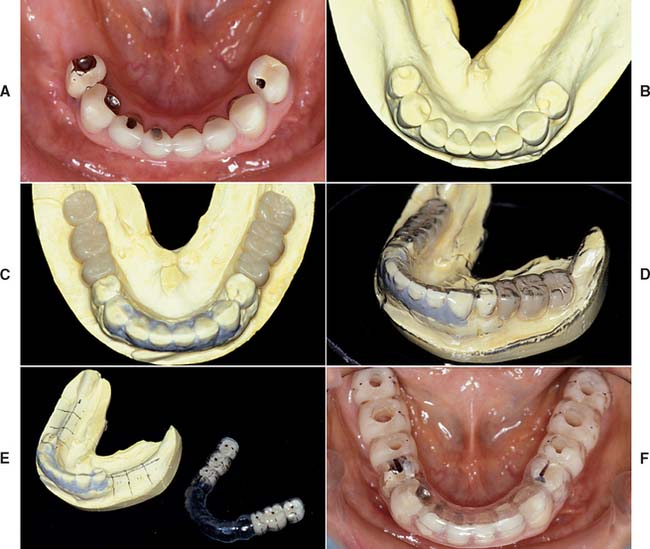
Fig. 13-9 A, Patient with bilateral missing posterior teeth planned for posterior implant-supported restorations. B, Diagnostic cast. C, Diagnostic denture tooth arrangement to simulate three-unit fixed prostheses on each side of the mandible. D, Vacuumed matrix formed over the cast with 1.5-mm (0.060-inch) thermoplastic sheet. E, The matrix is marked with the most appropriate implant locations and alignments and then removed from the cast. F, The completed surgical guide with holes drilled to guide the surgeon during implant site preparation.
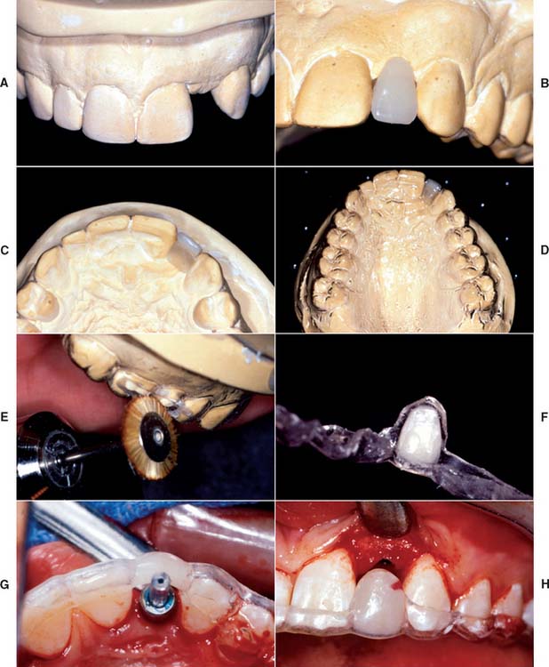
Fig. 13-10 A, Diagnostic cast with missing maxillary left lateral incisor. B, The denture tooth is positioned for optimum esthetics. C, The denture tooth is trimmed from the lingual side until it is 2 mm thick. D, If the tooth is held in position with light-cured composite, a vacuum matrix can be performed directly without duplicating the cast. E, The matrix can be trimmed to the height of contour with a stiff bristle brush. F, The denture tooth can be glued back into the matrix. G and H, The surgeon can use this template to guide both horizontal and vertical positioning.
Bone Sounding
When the results of clinical and radiographic examinations are equivocal and additional information is needed, sounding of the bone with a probe may be attempted. Under local anesthesia, a needle or sharp caliper is pushed through the tissue until it contacts bone. This can help the examiner judge soft tissue thickness at the planned implant sites.
PRINCIPLES OF IMPLANT LOCATION
Anatomic Limitations
To maximize the chance of success, the implant should be placed entirely within bone and away from significant anatomic structures (e.g., the inferior alveolar canal). Ideally, 10 mm of vertical bone dimension and 6 mm of horizontal should be available for implant placement. Placement at these dimensions prevents encroachment on anatomic structures and allows 1.0 mm of bone on both the lingual and the facial aspects of the implant. There should also be adequate space between adjacent implants. The minimum recommended distance varies slightly among implant systems but is generally accepted as 3.0 mm (Fig. 13-11). This space is needed to ensure bone viability between the implants and to allow adequate oral hygiene once the restorative dentistry is complete. Specific limitations resulting from anatomic variations among different areas of the jaws also must be considered. These include implant length, diameter, proximity to adjacent structures, and time required for integration.
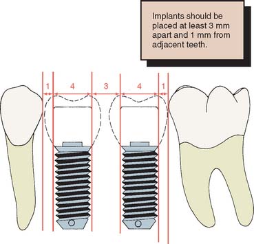
Fig. 13-11 Recommended minimum distances (in millimeters) between implants and between implants and natural teeth.
The anterior maxilla, posterior maxilla, anterior mandible, and posterior mandible each require special considerations in placing implants. Some common guidelines include staying 2.0 mm above the superior aspect of the inferior alveolar canal, 5.0 mm anterior to the mental foramen, and 1.0 mm from the periodontal ligament of adjacent natural teeth.
After tooth loss, resorption of the ridge follows a pattern that results in crestal bone thinning and a change in angulation of the residual ridge. These sequelae most often cause problems in the anterior mandible and maxilla. The irregular anatomy of the residual ridge may lead to problems with achieving ideal implant angulation or adequate bone thickness along the labial aspect of the implant. Techniques for the management of these problems during surgery are discussed in this chapter, but they must be anticipated in the preoperative phase.
Anterior maxilla
The anterior maxilla must be evaluated for proximity to the nasal cavity. A minimum of 1.0 mm of bone should remain between the apex of the implant and the nasal vestibule. Because of resorption of the anterior maxilla, the incisive foramen may be located near the residual ridge, especially in patients whose edentulous maxilla has been allowed to function against a natural mandibular anterior dentition. Anterior maxillary implants should be located slightly off midline, on either side of the incisive foramen.
Posterior maxilla
Implant placement in the posterior maxilla poses two specific concerns. First, the bone of the posterior maxilla is less dense than that of the posterior mandible. It has larger marrow spaces and a thinner cortex, which can affect treatment planning, inasmuch as increased time must be allowed for integration of the implants and additional implants may be needed. A minimum of 6 months is usually needed for adequate integration of implants placed in the maxilla. In addition, one implant for every tooth that is being replaced is normally recommended, especially in the posterior maxilla.
The second concern is that the maxillary sinus is close to the edentulous ridge in the posterior maxilla. Frequently, because of the resorption of bone and increased pneumatization of the sinus, only a few millimeters of bone remain between the ridge and the sinus (Fig. 13-12A). In treatment planning for implants in the posterior maxilla, the surgeon should leave 1.0 mm of bone between the floor of the sinus and the implant so the implant can be anchored apically into cortical bone of the sinus floor. Adequate bone height for implant stability can usually be found between the nasal cavity and the maxillary sinus. If there is not adequate bone for implant placement and support, bony augmentation through the sinus should be considered (see Fig. 13-12).
Anterior mandible
With regard to anatomic limitations, the anterior mandible is usually the most straightforward area for treatment planning. It usually has adequate height and width for implant placement, and the bone quality is normally excellent; therefore, it requires the least amount of time for integration. Success with immediate loading of implants in the anterior mandible has been reported. This seems to be possible because the implants can have good initial stability.
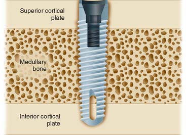
When possible, an implant in the anterior mandible should be placed through the entire cancellous bone so that the apex of the implant engages the cortex of the inferior mandibular border (Fig. 13-13). In the premolar area, care must be taken that the implant does not impinge on the inferior dental nerve. Because this nerve courses as much as 3.0 mm anterior to the mental foramen before turning posteriorly and superiorly to exit at the foramen, an implant should be at least 5.0 mm anterior to the foramen.
Posterior mandible
The posterior mandible poses some limitations on implant placement. The inferior alveolar nerve traverses the mandibular body in this region, and treatment planning must allow for a 2.0-mm margin from the apex of the implant to the superior aspect of the inferior alveolar canal. This is an important guideline: Disregarding it can cause damage to the nerve and numbness of the lower lip. If ade-quate length is not present for even the shortest implant, nerve repositioning, onlay grafting, or a conventional nonimplant-supported prosthesis must be considered.
Implants placed in the posterior mandible are usually shorter, do not engage cortical bone inferiorly, and must support increased biomechanical occlusal forces once they are loaded, because of their location in the posterior area. Consequently, allowing slightly more time for integration may be beneficial. In addition, if short implants (8 to 10 mm) are used, “overengineering” and placing more implants than usual to withstand the occlusal load is recommended. Short implants are often necessary because of bone resorption, which thus increase the crown/implant ratio when the normal plane of occlusion is reestablished (Fig. 13-14).
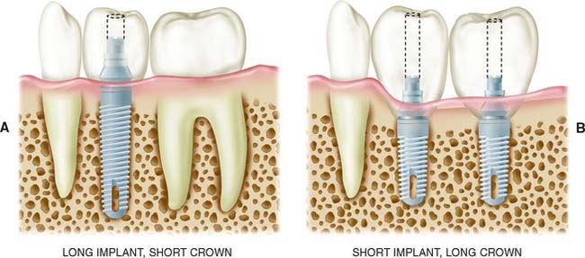
Fig. 13-14 Shorter implants usually have two problems: (1) less bone contact and (2) longer crowns, which increase the forces acting on the implant. More favorable crown-to-implant ratios (A) have a better prognosis than less favorable ratios (B).
The width of the residual ridge must be carefully evaluated in the posterior mandible. Attachments of the mylohyoid muscle maintain it along the superior aspect of the ridge, and a deep (lingual) depression exists immediately below it. This area should be palpated at the time of evaluation and examined at the time of surgery.
Restorative Considerations
Implant placement
Implant placement is crucial in the design of the restoration. Thus, the treatment-planning aspects of implant placement must begin with a restorative dentistry consultation. Implant placement dictates the appearance, contour, and long-term function of the prosthesis. To prevent damage, staying at least 1.0 mm away from the adjacent natural tooth is essential, but staying as close to the natural tooth as possible is also important; therefore, acceptable contours can be created by the restorative dentist. For proper access during oral hygiene procedures, a minimum of 3.0 mm should be left between implants. In addition, implants must not encroach on the embrasure spaces or be angled so that screw access is necessary through the facial surfaces of the completed restoration (Fig. 13-15).
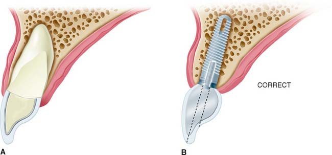
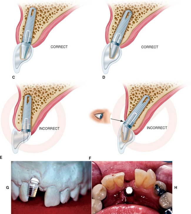
Fig. 13-15 Implant placement and angulation dictate the screw emergence position and crown contours. Esthetics and access for hygiene can be greatly affected. A, A restored tooth. B, Ideal implant location with acceptable crown contours and lingual screw emergence., C, Acceptable implant location for a cement retained crown. D, If the implant is more facially inclined, an angled abutment for a cement retained crown may be necessary. E, If the implant is too lingual and too shallow, inadequate crown contours for hygiene will result. F, If the implant is angled too far facially and too shallow, the implant and/or abutment may become an esthetic failure.
To minimize harmful lateral forces, the long axis of the implant should be positioned in the central fossa of the restoration. This dictates placing the implant accurately in all three planes of space. Superoinferior placement is important to ensure the optimal emergence profile of the restoration. Ideally, the superior surface of the implant should be 2.5 to 3.0 mm directly inferior to the emergence position of the planned restoration, particularly when the restoration is to be located in the anterior esthetic zone (Fig. 13-16).
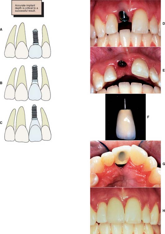
Fig. 13-16 Superior or inferior positioning may affect crown contours and pocket depth. A, The implant is not placed deep enough. This creates a short, overcontoured crown. B, Placement 2 to 3 mm apical to the tooth emergence position is ideal. C, Placing the implant 4 mm apical to the crown contours may create an excessively deep gingival sulcus. D to H, Clinical example of a properly positioned implant, both facially and apically, which results in good esthetics.
Implant and restoration size
The choice of implant and its superoinferior placement location are modified by the diameter of the intended restoration and can be adjusted for different sizes of teeth. For example, the typical root diameter of a maxillary central incisor is 8.0 mm; the average implant diameter is 4.0 mm. Therefore, a distance of 2.5 to 3.0 mm is needed to make the transition gradually from 4.0 to 8.0 mm. If this is done over too short a distance, the restoration will be overcontoured or look unnatural. In contrast, many mandibular central and lateral incisors are smaller than 4.0 mm at the cementoenamel junction. Therefore, an esthetic restoration on a 4.0-mm implant is impossible. Smaller-diameter implants (about 3.0 mm) are available to allow esthetic restoration in these areas. It is also possible to use a larger implant (5.0 to 6.0 mm) for molar restorations in patients with adequate bone (Fig. 13-17).
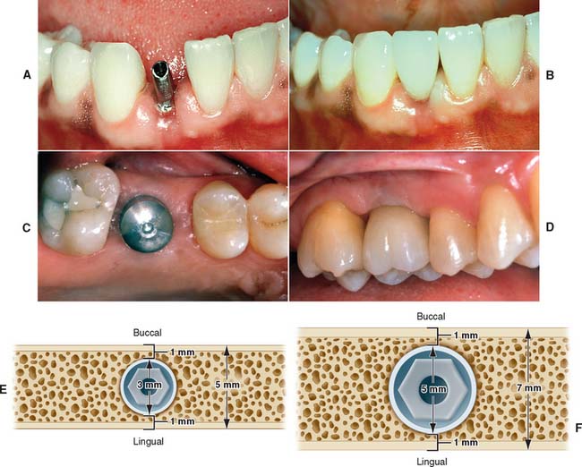
Fig. 13-17 A, Small-diameter implant and abutment positioned to restore a mandibular lateral incisor. The fixed abutment can be custom prepared and narrowed to allow restoration of a small-diameter tooth. B, Completed implant restoration of the mandibular lateral incisor. C, Wide-diameter (5.0 mm) implant in position to replace maxillary first molar. D, Completed implant restoration of the maxillary first molar. E, The minimum bone dimension for a small diameter implant is 5 mm. Ideally, at least 1 mm of bone is still left on either side of the implant site after the osteotomy has been prepared. F, The minimum bone dimension for a wider (5 mm) implant is approximately 7 mm. At least 1 mm of bone should still remain laterally after the site has been prepared.
Restoration size must always be considered during the treatment planning stage so that a properly sized implant is placed in the ideal location.
Single tooth implant
Treatment planning for the single tooth restoration, particularly in the anterior esthetic zone, is one of the most challenging problems faced by the implant restorative dentist. Placement of the implant for both esthetics and biomechanical loading (to minimize screw loosening) is especially crucial. In addition, at the treatment planning stage, the decision to place an implant with an antirotational feature built into the system (e.g., a spline or a hexagon) is essential (Fig. 13-18).
Soft tissue contours
For implant treatment planning in the anterior esthetic zone, it is important to look closely at the soft tissues that will frame the restoration. It can be challenging to achieve a completely formed papilla between the implant restoration and the adjacent teeth in the final outcome. If the interdental tissue and underlying bone have already been lost before implant placement, it may not be possible to achieve ideal papillary contours. The literature contains guidelines that help in predicting whether adequate soft tissue contour can be maintained. As diagrammed (Fig. 13-19), the relationship of interdental bone to the interproximal contact seems to predict whether an interdental papilla will be present or not. If the distances between the bone and the contact is short (∼5 mm), a papilla is usually present. If the distance is long ∼8 mm), a papilla would not normally be present without additional soft tissue grafting.9,10
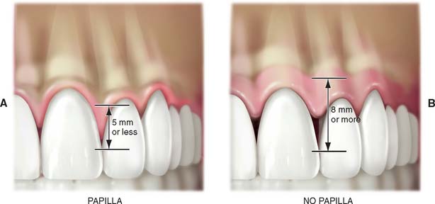
Fig. 13-19 Relationship of interdental bone to position of interproximal contacts seems to predict whether interdental papilla will be present or not. If the distance between the bone and the contact is <5 mm (A), a papilla if usually present; if the distance is >8 mm (B), there is usually no interdental papilla present.
SURGICAL GUIDE
The coordination of surgical and prosthetic procedures through proper treatment planning is one of the more crucial factors in obtaining ideal esthetic results for the implant restoration. A surgical guide template is extremely useful for anterior implants because slight variations in angulation can significantly affect the appearance of the final restoration. Fabrication of the surgical guide template has become a requirement in patients in whom it is necessary to optimize fixed replacement and ensure correct emergence profiles. Surgical templates can also be beneficial in areas where esthetics is less important. The objectives for using a surgical template in partially edentulous patients are as follows: (1) delineate the embrasures, (2) locate the implant within the restoration contour, (3) align implants with the long axis of the completed restoration, and (4) identify the level of the cementoenamel junction or tooth emergence from the soft tissue.
A clear resin facial veneer template is recommended for anterior implant placement to allow the surgeon access to the osseous receptor site and an unimpeded view of the frontal and sagittal angulations as the site is being prepared. This type of template is fabricated from a diagnostic waxing or denture tooth arrangement on a mounted cast. The waxing is duplicated with alginate or polyvinyl siloxane and poured in quick-setting stone. Then 1.5-mm (0.060-inch)–thick of vacuum-formed matrix material is adapted to the replicated cast. For accurate orientation, the vacuum-formed matrix should be trimmed to extend over the full facial surface of the teeth being restored and about a third of the facial surface of the remaining dentition. This template is removed from the duplicate cast and returned to the original cast. A 2-mm thickness of autopolymerizing resin is added to the lingual surface to compensate for the space occupied by the porcelain on the implant restoration (Fig. 13-20). (The total thick-ness, including an additional millimeter from the vacuum-formed matrix, is about 3.0 mm.) To make surgical guides appear radiopaque, barium powder is often added to the resin during its fabrication (see Fig. 13-8). The surgeon must stay as close as possible to this guide during implant placement, which allows maximum flexibility in selecting an implant site without violating the facial surface or forcing screw access holes to be located inappropriately in the facial surface of the restoration. Following this guide enables the surgeon to place a fixture in the best location with minimum undesirable sagittal angulation. If a cement-retained restoration is desired, the orientation of the implant can be slightly more facial.
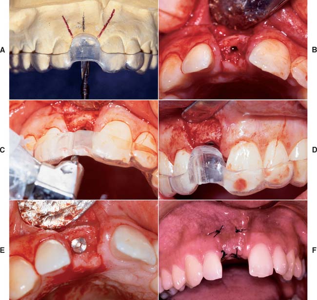
Fig. 13-20 Anterior implant placement with a surgical guide template. A, The apical extent of the template is not removed, which allows the superoinferior orientation of implant placement to be determined. B, Full-thickness flap incisions are made, preserving the interdental papilla. The flap is reflected to expose bone for preparation of the implant site. C, Resin (2.0 mm) has been added to the lingual aspect of the matrix; the rest of the lingual area was left open so the surgeon can choose the best available bone. The site should be prepared as close to the template as possible. D, The implant is positioned 2.5 to 3.0 mm apical to the desired emergence position of the final restoration. E, The implant is positioned at an angle and depth that allows optimum esthetics and access for hygiene. F, The surgical site is sutured. A 4 to 6-month healing time is allowed.
(Courtesy of Dr. J. A. Holloway.)
Although the use of a guide is most necessary in the maxillary anterior region, where bony dimensions are sometimes surprising and often unfavorable, the guide may also be useful in posterior areas with wide edentulous ridges. However, a different type of guide or template may be fabricated in this area. Holes are drilled through the resin into the underlying cast and are paralleled with a milling machine or dental surveyor. Such templates locate the placement of an implant and direct the inclination of its long axis with maximum accuracy.
Surgical templates also can be fabricated for a maxillary edentulous arch that is to be restored with a fixed prosthesis. Such templates are described later in the chapter, but the same preoperative planning and interspecialty cooperation are as important as just described.
IMPLANT SURGERY
Implant surgery can be performed in an ambulatory setting with the patient under local anesthesia. However, it requires more time than do other surgical procedures, and so conscious sedation may be preferred. Patients expect implant placement to be more traumatic than extracting a tooth. In fact, it is less traumatic. Preoperative education and conscious sedation should lessen the anxiety.
A complete description of the surgical procedures involved in implant placement can be found in one of the current standard texts.11,12
Surgical Access
Several types of incision can be used to gain access to the residual ridge for implant placement. The incision chosen should allow retraction of the soft tissue for unimpeded implant placement and should preserve attached tissue esthetics and quantity.
When the quantity of attached tissue is adequate and the underlying bone is expected to be of sufficient width, a simple crestal incision is recommended. However, closure must be performed carefully, because the implant lies directly beneath. In the posterior mandible, an incision may be placed toward the buccal aspect of the ridge to allow the flap to be retracted by a suture. This may be a disadvantage, however, because the incision line is thus immediately over the area where the bone may be thinnest, and a dehiscence can occur during surgery. An incision slightly to the palatal side is particularly effective in the maxillary anterior zone. After the bone is exposed, the surgical template is positioned, and a periodontal probe is used to make a preliminary assessment of the potential implant site. The residual ridge may have areas that are uneven or with sharp ridges. These areas should be smoothed before implant placement.
Implant Placement
Placement procedures for all implant systems require atraumatic preparation of the recipient site. Thermal injury to bone is minimized by using a low-speed, high-torque handpiece, along with copious irrigation. The irrigation is either externally or internally applied and directed through channels in the drill. Manufacturer recommendations relating to the type of irrigation and speed of the drilling equipment should be followed. Threaded implants often require final thread preparation in the bone at very low speeds.
The implant recipient site is prepared with a series of gradually enlarged burs. All implant systems have an initial small-diameter drill used to mark the implant site. The implant site is located through use of the surgical template, which may also assist in directing angulation of the implant. The center of the implant recipient site is marked with the initial drill, and a pilot hole is prepared. A paralleling pin is then placed in the preparation to check alignment and angulation.
At this point, a final determination is made regarding the adequacy of the recipient site for implant placement. Although implant placement is a surgical procedure, it is influenced by critical restorative parameters. The template communicates the range of acceptable implant positions and angulations. At this step, if it is apparent that supporting bone will not allow proper positioning of the implant, further osseous augmentation may be necessary, either simultaneously with implant placement or as a separate procedure with implant placement delayed until proper osseous support is available.
After the desired depth and diameter of the recipient site are achieved, the implant is placed. For titanium implants, an uncontaminated surface oxide layer is required for osseous integration. Hydroxyapatite-coated implants are also sensitive to contamination.
Nonthreaded implants are positioned in the recipient site and gently tapped into place with a mallet and seating instrument. Threaded implants are screwed into place, which also requires cutting the screw threads in the recipient site. Self-tapping implants are available for use in the maxilla, where the bone is soft enough to make prethreading unnecessary. After all implants are placed, tension-free closure prevents wound dehiscence.
Postoperative Evaluation
A radiograph should be taken postoperatively to evaluate the position of the implant in relation to adjacent structures (e.g., the sinus and the inferior alveolar canal) and other implants. Any significant problems noticed at this time should be corrected.
Patients are given mild analgesics and 0.12% chlorhexidine gluconate rinses for 2 weeks after surgery to keep bacterial populations to a minimum during healing. Weekly evaluations are recommended until soft tissue healing is complete (2 to 3 weeks). If possible, complete or partial removable dental prostheses should not be worn for 1 week after surgery. The resin over the implant can then be reduced by 2.0 or 3.0 mm and replaced with a soft liner, so that the denture can be worn without injuring the healing implant site.
Implant Uncovering
If a two-stage system is used, implant uncovering is performed after complete implant fixture integration has been achieved. The time interval for integration to occur varies and depends on the particular site and patient. Longer times may be required if the bone quality and surgery were less than ideal or if the bone-implant interface was questionable at the time of placement. In general, recommended integration times are 6 months in the maxilla, 3 months in the anterior mandible, and 4 months in the posterior mandible.
The goals of surgical uncovering are to accurately attach the abutment to the implant, to preserve attached tissue, and to recontour tissue as necessary. These goals may be accomplished with any of these three techniques: the tissue punch, crestal incision, or flap repositioning.
After the implant is exposed, the implant abutment is placed. There are two approaches for this procedure. The first approach is to place the same abutment as will be used in the restoration. The second approach is to place an interim healing cap that will remain until the tissue heals and will then be replaced by the abutment during the restorative treatment procedures.
When the abutment is placed, the superstructure must be completely seated on the implant body without gaps or intervening tissue. In systems with antirotational facets in the implant (see Fig. 13-18), these features must be aligned to allow complete seating of the abutment. Thesuperstructure–implant body interface should be evaluated radiographically immediately after the uncovering. If a gap is present, the superstructure must be repositioned.
IMPLANT RESTORATIONS
Osseous integrated implants are generally designed to support screw- or cement-retained dental prostheses. These implant systems offer many advantages over conventional dental restorations and one-stage implants (Box 13-3).
Fabrication of screw-retained prostheses requires a number of components unique to implant dentistry. For less experienced clinicians, the large number of parts included within one system might create problems. This section describes in generic terms the component parts typically needed to restore an osseous integrated implant. There are many dental implant systems, and although all the major components are available for each system, many differ slightly in specific design and materials. The basic steps for implant restoration fabrication are described in Figure 13-21.
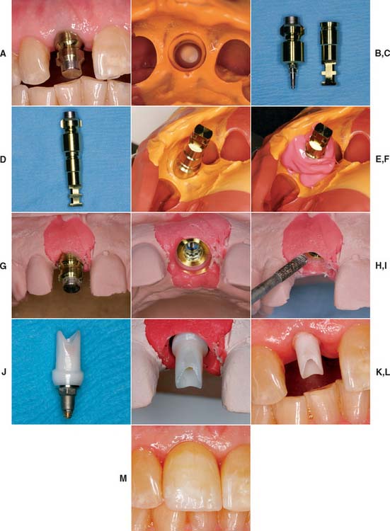
Fig. 13-21 A, A single-unit implant-supported prosthesis will replace the maxillary right central incisor. The impression post is tightened into the implant. B, A closed tray impression of the impression coping. C, Impression coping removed from the mouth. Pictured adjacent to implant analog. D, Impression coping attached to implant analog and inserted into impression (E). F, Polyether soft tissue cast material (Permadyne, 3M-ESPE North America, St. Paul, Minnesota) injected around analog before pouring. G, Poured cast. After an impression is made, the impression post is removed from the mouth and attached to the implant analog. Impression coping and analog are relocated in the impression before pouring. H, The impression coping locates the analog in the same position on the cast as the implant is in the mouth. I, Soft tissue cast material can be contoured to mimic adjacent tooth emergence profile. J, Abutment for cement-retained restoration selected. K, Zirconia abutment seated on the cast and ready for fabrication of all-ceramic restoration (see Chapter 25). L, Zirconia abutment seated in the mouth. M, All-ceramic restoration.
Clinical Implant Components
Terms used to describe similar implant components vary widely among manufacturing companies. A list of terms used in this book and a partial list of alternative terms are provided in Table 13-1.
Table 13-1 IMPLANT TERMINOLOGY
| Text term | Also known as | Function |
|---|---|---|
| Implant body (see Fig. 13-22) | Implant fixture screw or cylinder | Portion of the implant system within the bone |
| Healing screw (see Fig. 13-23) | Sealing screw | Seals the occlusal surface of the implant during osseointegration, if a two-stage procedure is used |
| Cover screw | ||
| First-stage cover screw | ||
| Interim abutment (see Fig. 13-24) | Temporary gingival cuff | A cover, attached to the implant, that is used to maintain the opening through the tissue until the restoration is completed. Is placed immediately onto the implant if a one-stage protocol is used. |
| Healing collar | ||
| Implant healing cap | ||
| Healing abutment | ||
| Healing cap (see Fig. 13-24B) | Temporary screw | A cover that is attached to the top of a transmucosal abutment, protecting the internal threads and interface surfaces of the abutment while the restoration is being completed |
| Comfort cap | ||
| Abutment healing cap | ||
| Standard abutment (see Fig. 13-25A) | An intermediate component placed between the implant and metal framework/restoration, providing support and retention for a fixed-removable restoration | |
| Excellent for bar overdentures | ||
| Tapered abutment (see Fig. 13-25B) | An intermediate component placed between the implant and restoration, providing support and retention for a fixed-removable restoration | |
| The abutment is cone shaped for maximum esthetics | ||
| Excellent for screw-retained fixed prostheses | ||
| Hex driver (see Fig. 13-33C) | Used for placing and removing all hex screws (i.e., abutment fastening screws), impression post-retaining screws, and healing abutments | |
| Available in two lengths—short (19 mm, for posterior) and long (24 mm, for anterior)—and three hex sizes (0.048, 0.050, and 0.062 inch) | ||
| Abutment driver or seating tool | Name of each driver/tool is specific, based on its use | Used to seat the abutment directly onto the implant |
| Impression coping (see Fig. 13-33A, B, and D) | Impression post | Component used during the impression procedure to transfer the position of the implant to the cast |
| Impression pin | ||
| Transfer pin | ||
| Transfer post | ||
| Implant analog (see Fig. 13-33G) | Implant fixed analog | Replicates the implant for use in the cast |
| Laboratory analog | ||
| Abutment analog | ||
| Implant body analog | ||
| Fixture replica | ||
| Interim abutment sleeve (see Fig. 13-47H) | Provides support and retention for acrylic temporary/interim restorations | |
| Provisional abutment | May also be used for occlusal rim and wax setup try-in procedures for overdentures | |
| Fixed abutment (see Fig. 13-25B and C) | Straight abutment | An abutment used for a cement-retained restoration (also available in 15- and 25-degree angles) |
| Coping abutment | ||
| Abutment post | ||
| Crown and bridge abutment (slang) | ||
| Waxing sleeve (see Fig. 13-37) | A castable plastic pattern usually attached to a premachined metal base used to form an abutment during the laboratory waxing procedure | |
| It interfaces directly onto the implant or onto the transmucosal abutment | ||
| Prosthesis-retaining screw (see Fig. 13-38) | Screw used to secure a screw-retained metal (bar) framework or restoration to transmucosal abutments (i.e., conical or standard abutments) |
Implant body
The dental implant body is the component placed within the bone during first-stage surgery. It may be a threaded or nonthreaded root form and is ordinarily made of either titanium or titanium alloy of varying surface roughnesses, with or without a hydroxyapatite coating (Fig. 13-22). Although some controversy exists regarding the optimum shape and surface coating for an implant in different parts of the mouth, the significant factors for success are precise placement, atraumatic surgery, unloaded healing, and passive restoration.
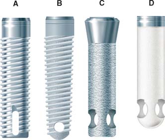
Fig. 13-22 Four main categories of osseous integrated implants. A, Titanium screw. B, Hydroxyapatite-coated screw. C, Hydroxyapatite-coated cylinder. D, Titanium plasma-sprayed cylinder.
All contemporary dental implants have an internally threaded portion that can accept second-stage screw placements. These implants also may incorporate an antirotational feature within the design of the fixture body. If it is incorporated, the antirotational feature may be either internal or external.
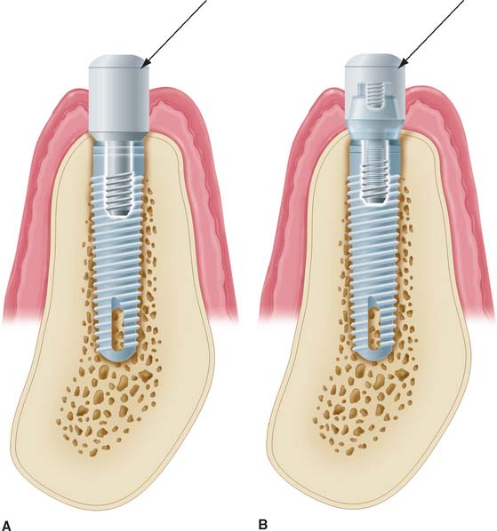
Implant bodies can also be classified as one-stage or two-stage. One-stage implants project through the soft tissue immediately after stage I surgery. Two-stage implants are typically covered with soft tissue at this point. When a tall healing screw or cap is placed on a two-stage implant to project it through the tissue at the time of placement, this is referred to as “using a two-stage implant with a one-stage protocol.”
Healing Screw
During the healing phase after first-stage surgery, a screw is normally placed in the superior aspect of the fixture. It is usually low in profile to facilitate the suturing of soft tissue in the two-stage implant or to minimize loading in the one-stage implant (Fig. 13-23). At second-stage surgery, it is removed and replaced by subsequent components. In some systems the screw is made slightly larger than the diameter of the implant, which facilitates abutment placement by ensuring that bone does not grow over the edge of the implant. The implant surgeon should always be sure that the healing screw is completely seated after stage-one surgery to prevent bone from growing between the screw and the implant. If this occurs, removing the bone may damage the superior surface of the implant and affect the fit of subsequent components.
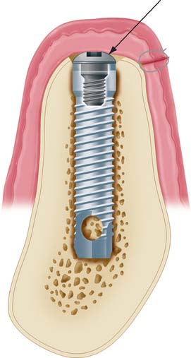
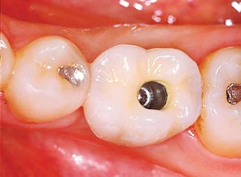
Fig. 13-23 Healing screw (arrow) in place during the initial implant-healing phase. Soft tissue is sutured over the implant. A removable prosthesis can be worn over this area during healing.
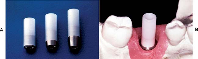
Interim abutment
Interim abutments are dome-shaped screws placed after second-stage surgery and before insertion of the prosthesis. They range in length from 2 to 10 mm and project through the soft tissue into the oral cavity. They may screw directly into the fixture or, in some systems, onto the abutment immediately after second-stage surgery. Those that screw onto the abutment are commonly referred to as healing caps (Fig. 13-24). Both interim abutments are made of titanium or titanium alloy. In areas where esthetics is paramount, healing should be sufficiently completed around an interim abutment to stabilize the gingival margin. At this time, abutments of appropriate length are selected to ensure that the metal-porcelain interface of the restoration will be located subgingivally. In areas where tissue esthetics is not crucial, adequate healing for impressions usually takes 2 weeks. In esthetic zones, 3 to 5 weeks may be required before abutment selection. In addition, knowing the length of the healing cap can expedite abutment selection.
Abutments
Abutments are the component of the implant system that screw directly into the implant. They eventually support the prosthesis in screw-retained restorations, inasmuch as they accept the retaining screw of the prosthesis. For cement-retained restorations, they may be shaped like a conventional crown prepara tion. Abutments take many forms (Fig. 13-25). Their walls are usually smooth, polished, and straight-sided titanium or titanium alloy. Their lengths range from 1 to 10 mm. In nonesthetic areas, 1 to 2 mm of titanium should be allowed to penetrate the soft tissue to maximize the patient’s ability to clean the prosthesis (Fig. 13-26). In esthetic areas, an abutment can be selected to allow porcelain to be carried subgingivally for optimum esthetics (Fig. 13-27).
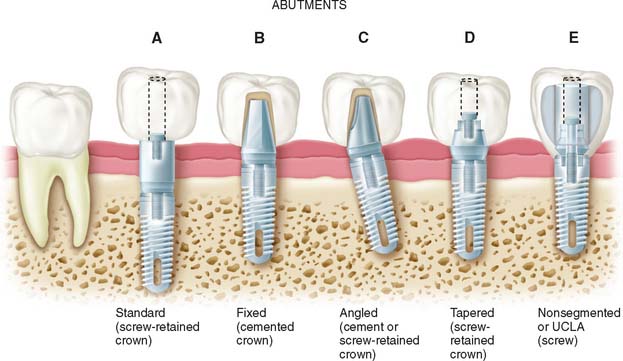
Fig. 13-25 Types of abutments (left to right). A, Standard. Length can be selected to make the margin subgingival or supragingival. B, Fixed. This abutment is much like a conventional post and core. It is screwed into the implants, has a prepared finish line, and receives a cemented restoration. C, Angled. This type is available when implant angles must be corrected for esthetic or biomechanical reasons. D, Tapered. This type can be used to make the transition to restoration more gradual in larger teeth. E, Nonsegmented, or direct. This type is used in areas of limited interarch distance or areas where an esthetic outcome is important. The restoration can be built directly on the implant, so there is no intervening abutment. This direct restoration technique has been called the UCLA abutment.
(Modified from Peterson et al: Contemporary Oral Surgery, 3rd ed. St. Louis, Mosby, 1998.)
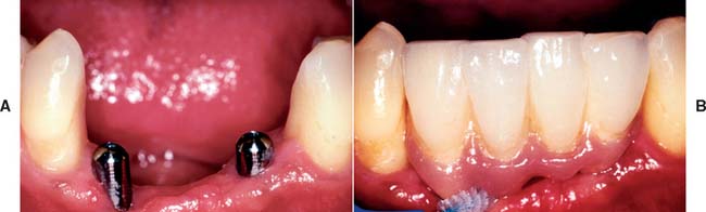
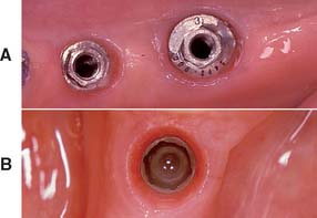
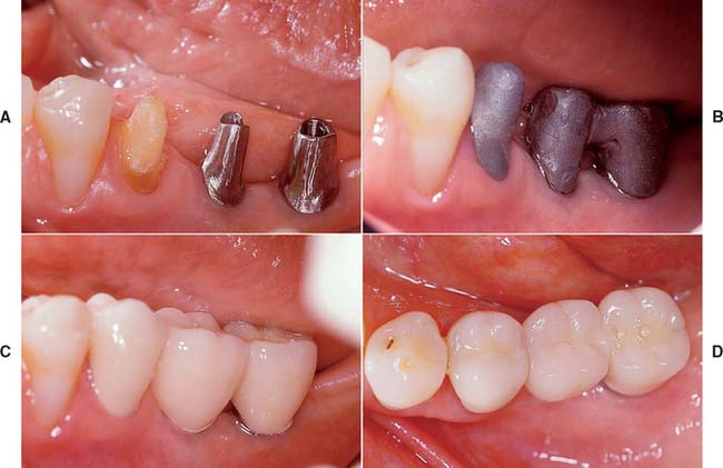
Fig. 13-26 A, Interim abutments projecting through the soft tissue. B, Implant restorations supported by standard abutments that allow easy access for oral hygiene.
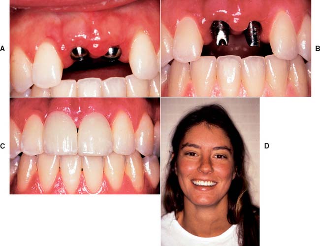
Fig. 13-27 A, Interim abutments projecting through the tissue for implant restoration of maxillary central incisors. B, Fixed abutments selected with margins 1 to 2 mm subgingival. C, Completed, cemented restorations. D, Overall esthetic result.
In implant systems that incorporate an antirotational feature, the abutment must have two components that move independently of each other: One engages the antirotational feature, and the other secures the abutment within the fixture (Fig. 13-28). With angled abutments, a similar technique is used to correct divergently placed implants (Figs. 13-29 and 13-30). Some systems have included tapered or wide-base abutments, which allow teeth with larger cross-sectional diameters to be restored with more physiologic contours. The nonsegmented implant crown (UCLA) bypasses the abutment portion by means of a sleeve waxed directly to the implant. Using nonsegmented implant crowns may be necessary when soft tissue thickness is less than 2 mm. All-ceramic components onto which all-ceramic crowns can be cemented are gaining popularity for the anterior part of the mouth. The ceramic components are usually made of sintered alumina, zirconia or a combination of the two.
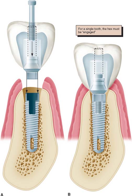
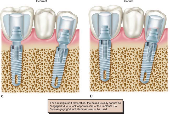
Fig. 13-28 A to D, When an antirotational feature is to be engaged by the abutment, one component of the abutment (the sleeve) must fit the hexagon, whereas the other (the screw) independently tightens the components together.
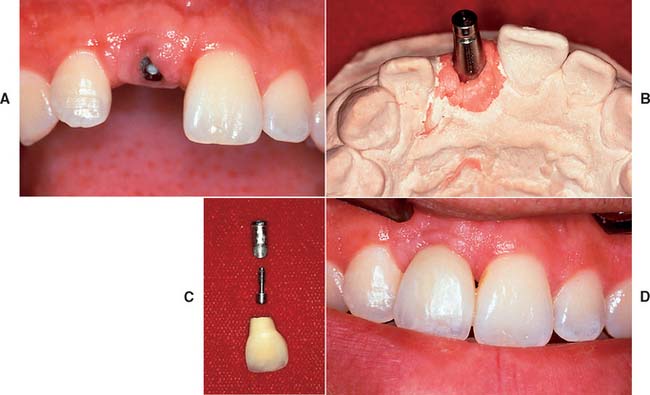
Fig. 13-29 A and B, This implant in the maxillary central incisor position is angled too far facially to restore with a straight abutment. C, An abutment angled 15 degrees with subgingival margins is chosen to rectify the situation. D, The completed crown cemented onto the angled abutment. An interim luting agent can be used to maintain retrievability, although choosing a suitable material that retains the restoration adequately but can still be removed is not always easy.
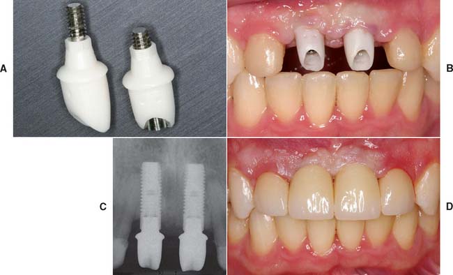
Fig. 13-30 A to D, Zirconia abutments with all-ceramic restorations used to replace missing maxillary central incisors.
(Courtesy of Dr. D. Gozalo.)
The choice of abutment size depends on the vertical distance between the fixture base and opposing dentition, the existing sulcular depth, and the esthetic requirements in the area being restored. For acceptable appearance, fixtures in the posterior maxilla or mandible may require margin termination at or below the gingival crest. An anterior maxillary crown may require 2 to 3 mm of subgingival porcelain at the facial gingival margin to create the proper emergence profile and appearance. Framework fit should be checked on multiple unit restorations if abutment margins are no more than 1 mm subgingivally. Periodontal probing of the sulcus after the healing cap is removed reveals the space available for subgingival extension and can be performed at the time of abutment placement or after a period of tissue healing around an interim restoration. When these measurements have been made, the correct abutment is attached to the implant. The abutment length can have a dramatic effect on restoration contours (Fig. 13-31).
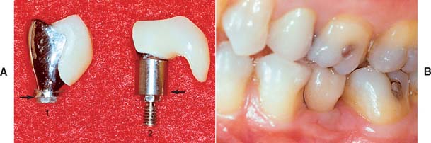
Fig. 13-31 A, Two crowns fabricated for the same lingually tipped mandibular implant. The arrows denote the connection to the implant body for both units. Crown 2 is fabricated on a 4-mm abutment. Crown 1 is connected directly to the implant body, allowing the creation of more physiologic contours. B, One-year follow-up of crown 1. The soft tissue response is excellent despite a poorly placed implant.
Impression copings
Impression copings facilitate transfer of the intraoral location of the implant or abutment to a similar position on the laboratory cast. They may screw into the implant or onto the abutment and are customarily subdivided into fixture types or abutment types (Fig. 13-32).
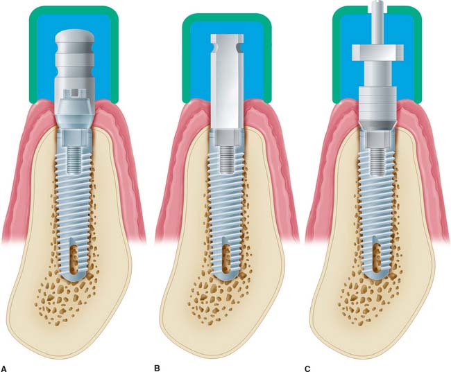
Fig. 13-32 Types of impression copings. A, A one-piece coping (screws onto abutment) is used if the abutment does not need to be changed on the laboratory cast. B, A two-piece coping (transfer/closed tray) is attached directly to the fixture if the abutment does need to be changed on the cast (it should have a flat side if angle correction is necessary). C, A two-piece coping (pickup/open tray), used to orient the antirotational feature or to make impressions of very divergent implants.
Both of these can be further subdivided into transfer (indirect) and pickup (direct) types. With the transfer impression coping in place, an impression is made intraorally, after radiographs are taken to confirm complete engagement. Heavier body impression materials (e.g., polyvinyl siloxane and polyether) are usually recommended, although any conventional impression material can be used. When the impression is removed from the mouth, the impression coping remains in place on the implant abutment or on the fixture. It is then removed from the mouth and joined to the implant analog before being transferred to the impression in the proper orientation. If the clinician anticipates that the implant angulation will have to be corrected on the laboratory cast, a flat-sided impression coping that goes directly into the fixture or implant should be used (Fig. 13-33). The flat side of the post accurately orients the location of the implant and positions the threads and the antirotational feature. When an angled abutment is placed or screwed onto the implant, it must be oriented in the same position in which the prosthesis was fabricated in the laboratory. Completely symmetric impression copings are contraindicated if angle correction may be necessary. If the clinician decides to transfer the orientation of an antirotational feature from the mouth to the laboratory model, the two-piece pickup (direct) impression technique should be used. This technique requires a two-piece impression coping with a removable guide pin that screws directly into the abutment or onto the fixture. A square coping with a long guide pin and usually an open-top tray are used. The impression coping is designed with square side walls to prevent rotation in the impression material. An open-top impression tray allows access to the guide pin for unscrewing after the material has set so that the copings can be picked up within the impression when removed from the mouth (Fig. 13-34). When implants are oriented at significantly divergent angles, the pickup technique is generally considered to be the more accurate of the two procedures. The transfer technique is more convenient and sometimes mandatory when space is limited and screwdriver access would be limited. Before an implant impression is taken, a radiograph should be made to ensure that the components are properly assembled. This requirement is especially important when an antirotational feature is involved.
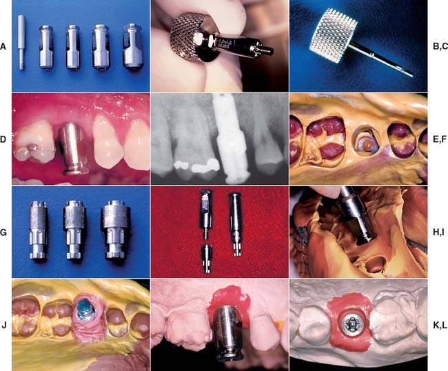
Fig. 13-33 A, A standard transfer impression coping is a sleeve that matches the implant diameter. A screw penetrates through its center. B, The screw can be placed through the impression coping sleeve and carried to the mouth with the standard hex driver (C). D, Impression coping seated into the implant. E, Radiograph confirming complete seating. F, Complete impression, clearly showing flat sides. G, Implant analog corresponding to the size of the implant. H, Impression coping removed from the mouth and attached to an implant analog. I, Impression coping/analog complex inserted into the impression with flat sides properly oriented. J, Polyether impression material injected around the complex before pouring. K and L, Impression coping orients the implant analog to the cast as the implant body is positioned in the mouth.
Implant analogs
Implant analogs are made to represent exactly the top of the implant fixture or the abutment in the laboratory cast. Therefore, they can be classified as fixture analogs and abutment analogs (Fig. 13-35). Both types screw directly into the impression coping after it has been removed from the mouth, and the joined components are returned to the impression before pouring. The final impression should be poured in either dental stone or die stone. The gingival tissues can be reproduced by injecting an elastomer (e.g., Permadyne*) to represent soft tissue around the implant analog before pouring. This facilitates removal of the impression coping from the stone cast and the placement of subsequent abutments without breaking the stone and losing the reference point of the soft tissue (Fig. 13-36).
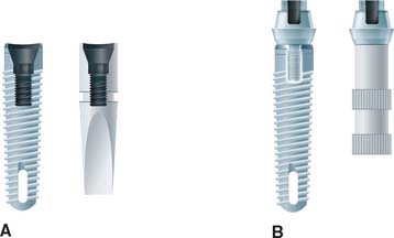
Fig. 13-35 Implant analogs. These represent either implants or abutments. A, Analog that duplicates the top of the implant. B, Analog that duplicates the top of the abutment.
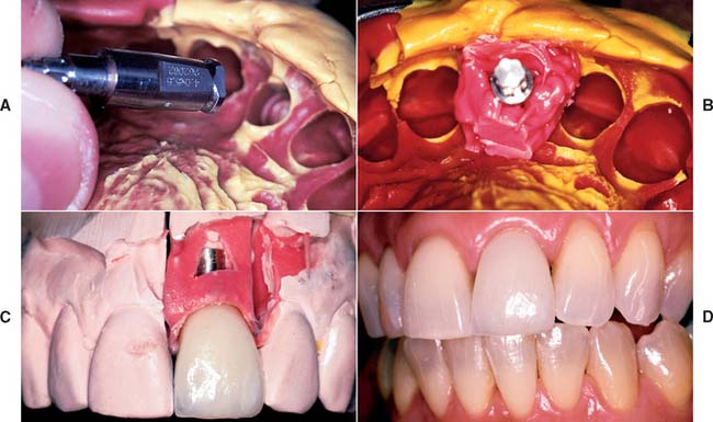
Fig. 13-36 A and B, Polyether impression material injected around an implant analog before the impression is poured. The gingival material should not cover any retention features of the analog. C, The impression material reproduces the patient’s soft tissue contours adjacent to the implant. The impression coping may be removed and other components inserted without losing the associated anatomic landmarks. D, Completed restoration.
(Courtesy of Dr. C. Pechous.)
Abutment analogs are generally attached to an implant impression coping. Implant body impression copings are normally attached to implant body analogs. The advantage of using the implant body analog is that the abutments can be changed in the laboratory. Also, if a flat-sided impression coping has been used to orient the threads or the hexagon of the implant body analog properly, the decision to correct for less than optimal implant angulation can be deferred until the laboratory stage. If the clinician is confident that the appropriate abutment has been selected, using the abutment impression coping and abutment analog can simplify the procedure. If a supragingival abutment margin has been selected, a soft tissue cast is not necessary.
Waxing sleeves
Waxing sleeves are attached to the abutment by the relating screw on the laboratory model. They eventually become part of the prosthesis. In nonsegmented implant crowns, they are attached directly to the implant body analog in the cast.
Commonly referred to as UCLA abutments, they may be plastic patterns that are burned out and cast as part of the restoration framework, precious metal that is incorporated in the framework when it is cast to the precious alloy cylinder, or a combination of each. Use of a metal waxing sleeve ensures that two machined surfaces are always in contact. The cast surface of the plastic waxing sleeve may be retooled before it is returned to the fixture.
Waxing sleeves are available in several vertical dimensions. Tall ones can be shortened to conform to the requirements of the occlusal plane. Today, most waxing sleeves are a combination of gold alloy and plastic (Fig. 13-37). This combination allows the machined fit of the alloy at the implant, with the cost advantage of plastic at the waxing surface.
Prosthesis-retaining screws
Prosthesis-retaining screws penetrate the fixed restoration and secure it to the abutment (Fig. 13-38). They are tightened with a screwdriver and attach nonsegmented crowns to the body of the implant. They generally are made of titanium, titanium alloy, or gold alloy and may be long (which allows them to penetrate the total length of the implant crown) or short (which requires countersinking them into the occlusal surface of the restoration). Screws that are countersunk must be covered by an initial layer of resilient material (e.g., gutta-percha, cotton, or silicone). A subsequent seal of composite resin is placed over the resilient plug (Fig. 13-39).
Implant Restorative Options
Distal-extension implant-supported restoration
Implant support offers major advantages in the treatment of partially edentulous patients in whom no terminal abutment is available. In this situation, the conventional dental treatment plan would include a partial removable dental prosthesis. However, with the implant alternative, patients can avoid the discomfort and inconvenience of a removable prosthesis.
There are two distal-extension restorative options. One option is to place an implant distal to the most posterior natural abutment and fabricate a fixed prosthesis connecting the implant with the natural tooth. However, there are problems associated with implants connected to natural teeth (see p. 422). The other option is to place two or more implants posterior to the most distal natural tooth and fabricate a completely implant-supported restoration (Fig. 13-40). If the crown/implant ratio is favorable, two implants to support a three-unit fixed dental prosthesis may be considered. If implants are short and crowns are long, one implant to replace each missing tooth is highly recommended. If doubt remains, more implants are used when heavier forces are expected (e.g., the posterior part of the mouth in patients with evidence of parafunctional activity). Fewer implants are used when lighter forces are expected (e.g., those opposing a complete denture or those supporting a prosthesis in the anterior part of the mouth).
Long edentulous span restoration
Similar options can be used to treat a long edentulous span. The clinician may choose to have multiple implants placed between the remaining natural teeth and to fabricate a fully implant-supported restoration. As an alternative, one or two implants can be placed in the long edentulous span and the final restoration connected to natural teeth. When it is necessary to connect implants and the natural teeth, protecting the teeth with telescopic copings is recommended. In this manner, prosthesis retrievability can be maintained. In addition, some long edentulous spans require the reconstruction of soft and hard tissue as well as teeth. In these instances, use of resin teeth processed to a metal substructure rather than a conventional metal-ceramic restoration is recommended. Soft tissue esthetics can be more easily and accurately mimicked with heat-processed resin and large defects (Fig. 13-41). This type of restoration is best described as a complete metal-resin fixed dental prosthesis. It has also been called a hybrid prosthesis because it combines the principles of conventional fixed and removable prosthodontics. For smaller defects, pink porcelain can be used to compensate for missing soft tissue (see Fig. 13-26B).
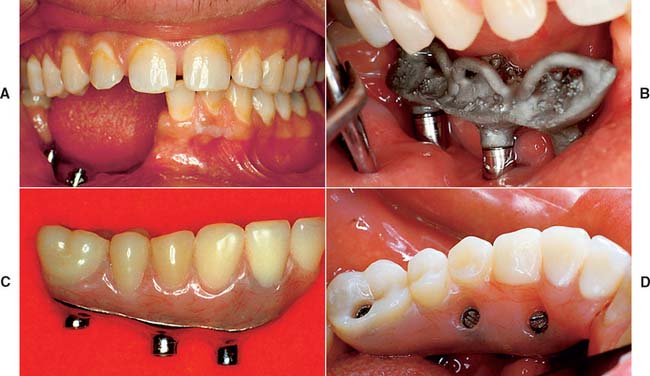
Fig. 13-41 A, Large mandibular defect created by a shotgun wound. B, Metal substructure of a metal-resin prosthesis tried onto three implants in this defect. C, Denture resin can more effectively recreate the soft tissue color and contours in the completed restoration than dental porcelain. D, Metal-resin restoration over the defect.
Single-tooth implant restoration
The use of single implants in restoring missing teeth is an attractive option for the patient and the dentist. However, it requires careful implant placement and precise control of all prosthetic components. Single-tooth restorations supported by implants may be indicated in the following situations:
The requirements for single-tooth implant crowns are as follows:
Several systems have been developed to comply with these demands. Common indications include congenitally missing maxillary lateral incisors (Fig. 13-42) and teeth in which endodontic treatment was unsuccessful (Fig. 13-43). Screw loosening has most commonly been associated with the terminally positioned single molar implant crown (Fig. 13-44).
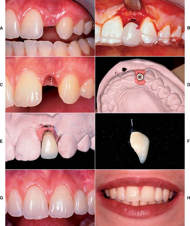
Fig. 13-42 A, Patient with congenitally missing maxillary lateral incisor. B, Placement of dental implant through the use of a surgical template. C, Final soft tissue contours. D, Impression post projecting from definitive cast. E and F, Final restoration. G and H, Single tooth implant crown replacing the maxillary lateral incisor.
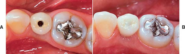
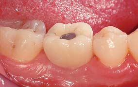
Fig. 13-43 A, Occlusal view of a single tooth implant crown replacing a fractured mandibular premolar. B, Implant crown with screw access restored.
Matching the soft tissue contours of adjacent natural teeth remains the most difficult challenge for completing the anterior single-tooth restoration. These contours can be reliably created with interim restorations. One technique, which combines soft tissue contouring and interim placement, is shown in Figure 13-45. When the tissue has matured around the interim restoration, a final impression can be made to complete the definitive restoration (Fig. 13-46). Impressions can also be made at the time of stage I surgery so that an interim restoration can be delivered at stage II to facilitate more ideal soft tissue contours (Fig. 13-47). The best soft tissue esthetics is still generally achieved when interdental papillae are present before the surgery. If soft tissue contours are deficient before surgery, the patient should expect some compromise in the final soft tissue result.
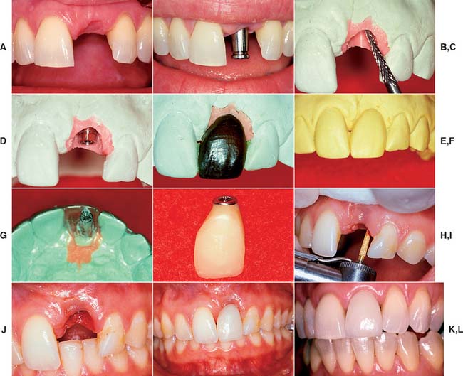
Fig. 13-45 Soft tissue contouring with interim restoration. A, This patient has lost the left maxillary central incisor, which will be replaced with an implant-supported prosthesis. B, Soft tissue healing 2 weeks after second-stage surgery and placement of an impression coping. Note that the interdental papilla has been preserved. C, Soft tissue cast prepared with a laboratory bur to create the ideal soft tissue architecture. D, A waxing sleeve attached to the implant analog retains the interim restoration. E, An anatomic-contour wax pattern can be used to fabricate the interim restoration. F, Duplicate cast of the anatomic-contour wax pattern. G, An acrylic template is adapted to the duplicate cast and returned to the definitive cast. A waxing post is placed in the interim restoration to create a screw access hole. H, An interim implant-supported restoration is fabricated by one of the techniques described in Chapter 15. I, The soft tissue is contoured to accept the interim restoration. A diamond curettage bur can be used when sufficient attached tissue is present. J, Soft tissue contouring improves esthetics, minimizes pocket depths, and allows more physiologic restoration contours. K, The interim restoration. Soft tissue is allowed to heal for 4 to 6 weeks before the definitive impression is made. L, Definitive implant-supported restoration.
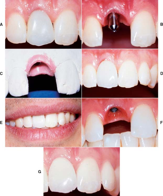
Fig. 13-46 A, Soft tissue around a maxillary implant provisional restoration after 6 weeks of healing. B, New soft tissue contours compared to the healing abutment previously in place. C, Final impression made and a definitive cast fabricated. The new soft tissue contours are reproduced. D, Implant crown placed on the maxillary right central incisor. E, Preservation of the interdental papilla is important for patients with medium to high smile lines. F and G, One- and five-year follow-ups showing that the patient has maintained healthy soft tissue contours.
(Courtesy of Dr. J.A. Holloway.)
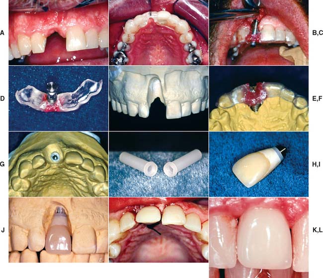
Fig. 13-47 Stage II interim restoration technique. A, View of missing maxillary right central incisor. B, Surgical template in position. C, Once the screw-shaped implant is in place, the fixture mount is luted to the surgical template with resin before it is unscrewed from the mouth. D, Analog attached to the fixture mount. E, Diagnostic stone cast prepared to position analog. F, Template placed back on diagnostic cast. G, Dental stone is flowed around the analog. The position of the analog is identical to the position of the implant in the mouth. H to L, A plastic sleeve is used for the fabrication of an interim restoration that can be delivered at stage II surgery.
Fixed restoration in the completely edentulous arch
For completely edentulous patients who require nonremovable restorations, there are two implant options: a complete metal-resin fixed dental prosthesis and a metal-ceramic fixed dental prosthesis (Figs. 13-48 to 13-50).
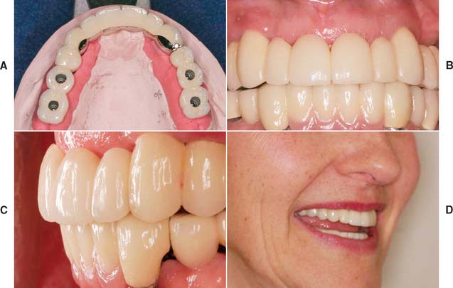
Fig. 13-48 A to D, A metal-ceramic implant restoration may be indicated if adequate bone and soft tissue contours are available.
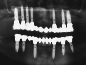
Fig. 13-49 Radiograph showing fixed restorations supported by seven implants in the maxilla and six in the mandible. Radiograph of patient in Fig. 13-48.
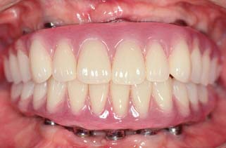
Fig. 13-50 Metal-resin restorations are the treatment of choice for edentulous patients with moderate bone resorption.
The complete metal-resin fixed dental prosthesis is a cast alloy framework with processed denture resin and teeth. It is typically supported by a minimum of five implants in the mandible and six in the maxilla. One major determining factor for selecting this option is the amount of bone and soft tissue that has been lost. For patients who have had moderate bone loss, the prosthesis restores both bone and soft tissue contours.
The metal-ceramic prosthesis also requires a minimum of five implants in the mandible and six in the maxilla. It can be made esthetically pleasing only if bone loss is minimal and is best suited for patients who have recently (within 5 years) lost their natural teeth. For patients with severe bone loss, there is probably only one option: a removable restoration (Fig. 13-51).
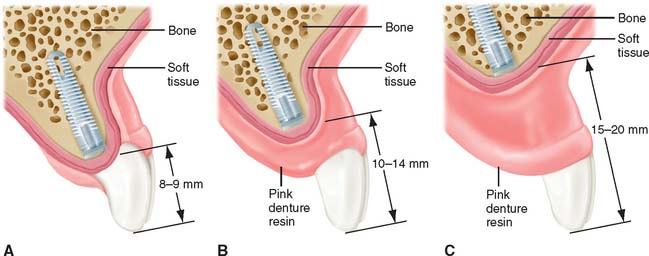
Fig. 13-51 The amount of bone resorption dictates the treatment options for an edentulous patient. A, Minimal resorption may allow metal-ceramic restorations. B, Moderate resorption may necessitate resin-to-metal restorations. C, Severe resorption necessitates only implant-supported overdentures for optimum esthetic results.
The main advantage of a fixed restoration, whether it is metal-resin or metal-ceramic, is that it is attached to the implants at all times. Therefore, patients experience the psychologic benefit of having a restoration that closely resembles their original natural teeth. In addition, movement within the system is minimized, and the components tend to wear out less quickly. Because the prosthesis is screw retained, the dentist can remove it, allowing access for cleaning and repairs. A potential disadvantage is that the implants must be precisely placed, especially in the maxillary anterior esthetic zone. Implants placed in embrasure spaces can lead to disastrous esthetic results and can impede access for hygiene. With a metal-resin prosthesis, the clinician must decide between leaving enough space for hygiene access and minimizing space for optimum esthetics. Some patients may be concerned by the amount of metal shown in a metal-resin prosthesis. However, from a conversational distance, a properly made prosthesis is hardly noticeable. Esthetic and phonetic problems in the maxillary arch can often be avoided by not placing implants near the midline and restoring the incisor teeth with pontics. This approach to implant placement improves the restorative outcome considerably (Fig. 13-52).
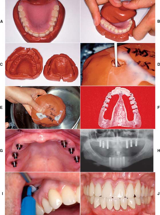
Fig. 13-52 Posterior implant placement for a maxillary complete arch prosthesis. A surgical template can be fabricated for an edentulous patient by duplicating the existing denture in clear resin. A to C, Putty impression material is used to form a mold of the fitting and polished surfaces of the denture, which is reassembled to form the mold. D, Clear autopolymerizing resin is poured into the mold and placed in a pressure pot (E). F, The lingual aspect of the template is removed, leaving the most facial 2 mm of resin intact. The surgeon will have access to the bone, but it will be confined to the arch form. G, The ideal positions for maxillary implants are the canine, second premolar, and second molar areas. H, Cross-arch implant parallelism is also important. I, Access for hygiene must be allowed around implant abutments. If implants are located posterior to the canine, access for hygiene can be created without compromising esthetics or phonetics. J, Reasonable esthetics and phonetics can be accomplished with a metal-resin restoration if modified ridge-lap pontics are used in the maxillary central and lateral incisor positions.
Cement-Retained versus Screw-Retained Implant Crowns
Cemented implant crowns can be luted to a screw-retained abutment. Zinc phosphate, glass ionomer, and composite resin cements have all been suggested for this purpose. However, retrievability of the implant restoration is ordinarily not considered when a permanent cement is used. The interim cements have been recommended because they allow restoration retrieval. However, unpredictability of the interim luting agents can lead to a difficult retrieval or premature displacement.13
Simplicity and, in some systems, economy are the major advantages of cement-retained restorations. In addition, cementing allows minor angle corrections to compensate for discrepancies between the implant inclination and the facial crown contour (Fig. 13-53). Resistance to rotation is particularly crucial with cemented prosthetics, and the abutment should then incorporate an antirotational feature. Very small teeth are most easily replaced with cement-retained implant crowns.
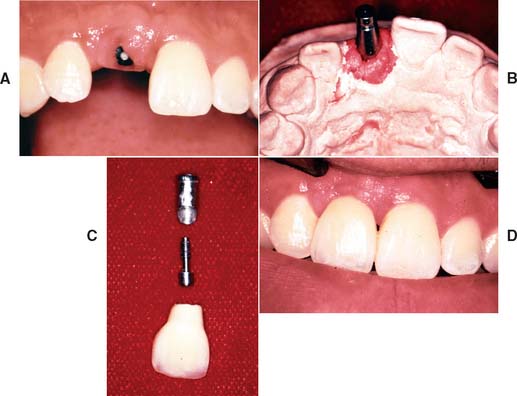
Fig. 13-53 A, Implant in position to replace the maxillary right central incisor. B, A laboratory cast demonstrates facial angulation of the implant. C, An angled abutment allows esthetic restoration (D). A cement retained restoration would be necessary to avoid a hole through the facial surface.
One misconception about cement-retained crowns is that they are simpler and have fewer screw-loosening episodes. They actually may require more chair time and have the same propensity to loosen as does a directly screw-retained restoration. They are, however, more esthetically pleasing and less expensive.
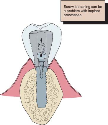
The screw-retained implant crown is fastened either to the abutment or directly to the implant. The main advantage of this restoration is its retrievability. Retrievability allows for crown removal, which can facilitate soft tissue evaluation, calculus débridement, and any other necessary modifications. In addition, future treatment considerations can be made more easily and are less costly if the implant restoration is retrievable. However, in screw-retained restorations, the access hole must be through the occlusal table of posterior teeth or the lingual surface of anterior teeth. Forces can then be directed in the long axis of the implant, and an optimum esthetic outcome is more easily achieved. This requirement dictates an ideal surgical location, which is not always possible because of anatomic limitations. A possible disadvantage of a screw-retained implant restoration is that the screw may loosen during function. Many techniques for retaining screw connection have been reported.14 The direct mechanical interlock or antirotational feature appears to be the most effective.
If the screw is sufficiently tightened into the implant crown to seat it, a clamping load or preload is developed between the implant and the crown (Fig. 13-54). If this clamping force is greater than the forces trying to separate the joint between implant and crown, the screw will not loosen. A restoration screw should be tightened with sufficient force to seat the crown, but not so much as to affect the bone-implant interface. Torque wrenches are available to achieve this. In addition, lateral forces (which tend to separate the joint) should be eliminated or reduced (Fig. 13-55 and Box 13-4.)
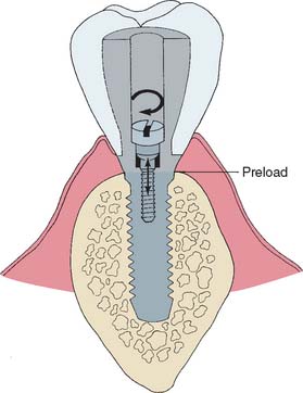
Fig. 13-54 Torque on the screw develops a preload (clamping force) between the implant and the crown.
BIOMECHANICAL FACTORS AFFECTING LONG-TERM IMPLANT SUCCESS
Occlusion
Bone resorption around dental implants can be caused by premature loading or repeated overloading. Vertical or angular bone loss is usually characteristic of bone resorption caused by occlusal trauma (Box 13-5). When pressure from traumatic occlusion is concentrated, bone resorption occurs by osteoclastic activity. In the natural dentition, bone remodeling typically occurs once the severe stress concentration is reduced or eliminated. However, in the osseous integrated implant system, after bone resorbs, it usually does not re-form. Because dental implants most effectively resist forces directed primarily in their long axis, lateral forces on implants should be minimized.
Lateral forces in the posterior part of the mouth are greater and more destructive than lateral forces in the anterior part of the mouth. When they cannot be completely eliminated from the implant prosthesis, efforts should be made to distribute them equally over as many teeth as possible.
Implant restorations should be designed to minimize damaging forces at the implant-bone interface, with particular attention to the occlusion.15 Flatter inclines can be developed on implant-supported cusps, creating more vertical resultant forces and a shorter moment arm (Fig. 13-56). Whenever possible, a cusp-fossa relationship should be established in maximum intercuspation with no eccentric occlusal contacts (see Chapter 18). The maxillary single-tooth restoration is vulnerable to screw loosening as a result of occlusal contacts, which usually produce an inclined resultant force with increased torque on the retaining screw. Optimum implant orientation effectively reduces these forces.
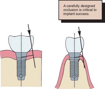
Fig. 13-56 Sharper cusp inclines and wider occlusal tables increase the resultant force on implant components.
In general, the location and inclination of force should be seriously considered in the restorative phase of implant treatment. Divergent implant placement increases the moment arm through which force is transmitted to the bone-implant interface; this could exceed the threshold for bone resorption. Interchangeable components to alter implant angles have been produced by implant body manufacturers. However, it has been shown16 that increasing abutment angles also produces increased stresses at the bone-implant interface. Angled abutments may solve immediate esthetic or contour problems while masking potential long-term consequences created by an implant placement that is poorly planned or dictated by the patient’s anatomy.
Inadequate implant distribution may also lead to excessive cantilevers or forces that could potentiate overloading of implant bodies. Whenever possible, dental implants should be joined so that forces may be more equally distributed over multiple implants. Ideally, one implant for every tooth to be restored should be placed. This number is particularly important when shorter implants are placed in bone of poorer quality. When implants longer than 13 mm can be placed in dense bone, two for every three teeth being replaced are acceptable. Complete arch restorations should not be considered on fewer than six implants in the maxilla and five in the mandible. Implant cantilevers should be kept as short as possible. However, cantilevering considerable distances off five well-integrated fixtures in the anterior mandible is possible. Quite often, cantilevering to the first molar is possible. Equations based on the distribution and length of fixtures have been proposed.17
Connecting Implants to Natural Teeth
It has been suggested18 that connecting a single osseous integrated implant to one natural tooth with a fixed dental prosthesis can create excessive forces because of the relative immobility of the osseous integrated implant in comparison with the functional mobility of a natural tooth. During function, the tooth moves within the limits of its periodontal ligament, which can create stress at the neck of the implant up to two times the implied load on the prosthesis (Fig. 13-57). Potential problems with this type of restoration include (1) breakdown of the osseous integration, (2) cement failure on the natural abutment, (3) screw or abutment loosening, and (4) failure of the implant prosthetic component. This situation is encountered clinically when the most posterior abutment is lost in the dental arch and a fixed prosthesis is needed to connect a single implant to the natural tooth. If possible, a totally implant-supported fixed dental prosthesis with two or more implants should be provided. However, anatomic limitations of the maxillary sinus or the mandibular canal often limit restorative efforts directed at a single fixture site.
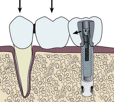
Fig. 13-57 When a single implant is attached to a natural tooth, biting forces on the natural tooth and pontic cause stress to be concentrated at the superior portion of the implant.
When connecting an implant to a natural tooth is necessary, multiple implant or natural tooth abutments should be used. A semiprecision attachment (keyway) in the prosthesis between the implant and the natural tooth may solve potential problems18 (Fig. 13-58). However, under most circumstances, when a load is applied to the pontic, the additional movement at the attachment actually increases the cantilever effect on the implant abutment. In practice, the only advantage of a semiprecision attachment may be that it allows a screw-retained implant abutment crown to be removed for periodic evaluation.
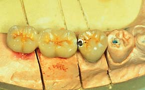
Fig. 13-58 A semiprecision attachment may compensate for vertical displacement forces in the tooth and an implant-supported fixed prosthesis. It does not compensate for forces in the buccolingual direction.
(Courtesy of Dr. G. Seal.)
When circumstances dictate use of a natural tooth abutment, a telescopic coping should be considered. This is permanently cemented to the natural tooth and can prevent decay if loosening occurs. Interim cement is used to attach the prosthesis to the coping. If it leaches out of the implant crown, the natural tooth is still protected (Fig. 13-59).
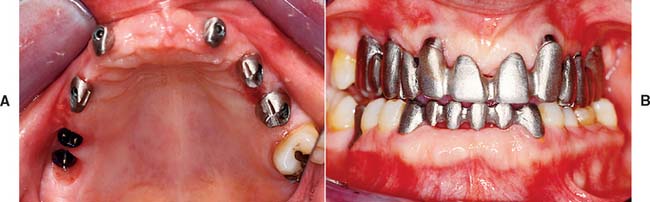
Implant and Framework Fit
Pathogenic forces can be placed on an implant if the framework does not fit passively. When all the prosthesis-retaining screws are tightened, gaps between the abutment and a poorly fitting framework close, giving the appearance of an acceptable fit. However, significant compressive forces are placed on the interfacial bone, which can lead to implant failure. The fit of all implant frameworks should be checked with only one screw in place. No visible amounts of space or any amounts of movement with finger pressure should be discernible on any of the other implant abutments (Fig. 13-60). If a nonpassively fitting framework is identified, it should be sectioned and soldered and then reassessed for passive fit. A relation record should also be made.
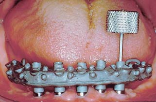
CAD/CAM Abutments and Frameworks
Recent technology has made it possible to design virtual abutments and frameworks with nearly unlimited design options. By scanning the dental cast of the interim abutment (Fig. 13-61), some manufacturers can fabricate final ceramic or titanium abutments of any shape or angle with computer-assisted design/computer-assisted machining (CAD/CAM) technology. Interimplant titanium frameworks fabricated with this technology have been reported to fit more accurately and passively than those fabricated with standard casting technology.
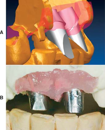
MAINTENANCE
The goal of implant maintenance is to eradicate microbial populations affecting the prosthesis. Although dental implants may be more resistant than natural teeth to the effects of bacterial plaque, this has yet to be definitively proved. Until more research is available, proper and timely home care measures for prolonging the lifetime of an implant are most effective. The clinician must ensure that the patient receives thorough instruction in maintenance techniques, including an initial session with the clinician. This should be reinforced by a training session with the dental hygienist during a recall visit. Recall visits should be scheduled at least every 3 months during the first year. The patient’s oral hygiene should be evaluated and documented at a recall visit; reinstruction should be provided when necessary. Sulcular debridement must be performed with plastic or wooden scalers, because conventional instruments scratch the titanium. Implant abutments may be polished by rubber cups with a low-abrasive polishing paste or tin oxide.
At each recall appointment, implant mobility should be evaluated; any bleeding after probing should be examined. Framework fit and occlusion also must be checked. Attention to both biologic and biomechanical factors is important for the long-term success of dental implants.
COMPLICATIONS
Bone Loss
The primary complication with dental implant therapy is bone loss around the implant (Fig. 13-62). Any loss exceeding 0.2 mm per year is cause for concern. Multiple factors are associated with implant bone loss:
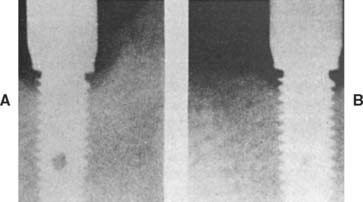
Fig. 13-62 To monitor implant bone loss, radiographs should be evaluated once a year. A, Post placement. B, One year follow-up.
The restorative dentist should pay particular attention to the fit of the prosthesis, the access for hygiene, and the presence of excessive occlusal forces. If bone loss reaches 25% to 30%, revision surgery should be considered.
Prosthetic Failure
Additional implant prosthetic complications include fracture of the implant components or of the prosthesis. Fracture of implant components is usually attributed to fatigue from biomechanical overload (Fig. 13-63). Failure of the implant prosthesis is usually traceable to less than ideal laboratory procedures or prosthesis design (Figs. 13-64 and 13-65).
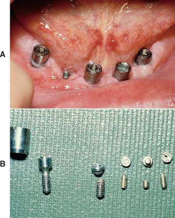
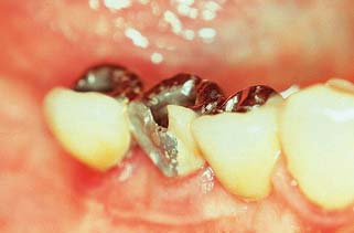
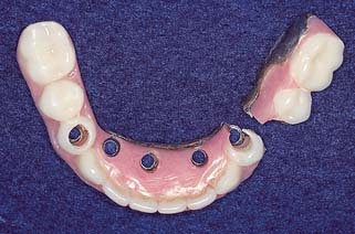
SUMMARY
Implant-supported prostheses, involving cylindrical osseous integrated fixtures placed by a two-stage surgical technique, should be considered in the treatment of any partially edentulous patient. They are a reliable solution to many situations that are difficult to treat by conventional measures: the patient who cannot wear removable appliances, the patient with a long edentulous span or other circumstance (e.g., short roots) that diminishes the prognosis for a fixed dental prosthesis, and the patient with a single missing tooth but sound adjacent teeth.
Success with implant prosthodontics requires the same attention to detail and careful planning as conventional fixed prosthodontics. Often a team approach is recommended, in which a surgeon places the implant and a restorative dentist designs the prosthesis. The crucial stage is optimum placement of the implant or implants. The surgeon’s main concern is that it be well within the available bone and away from vital structures (e.g., the inferior dental canal). The restorative dentist’s main concern is that the positioning and angulation of each fixture allow optimum occlusion, esthetics, and tissue health, as well as minimum stresses at the implant-bone interface. Information obtained from a clinical examination, radiographs, and a diagnostic waxing on articulated casts is crucial for planning. Surgery is guided by a template made from the diagnostic waxing.
Depending on the implant site, a two-stage surgical technique requires 3 to 6 months for bone to heal against the implant. In a second surgery, the implant is uncovered and implant abutments are screwed into place. Subsequently, a screw-retained prosthesis is fabricated to restore function and appearance.
Several implant systems are available, each with a variety of components for restorative management (e.g., an antirotational feature incorporated in an implant for single tooth replacement).
Problems unique to implant prosthodontics include screw loosening and bone loss from premature loading or repeated overloading. Occlusal considerations, prosthesis fit, plaque control, and follow-up care are all primary concerns to the professionals who deal with implants and conventionally supported prostheses.
 GLOSSARY*
abutment analog n (2005): a replica of the superior portion of a dental implant. Usually used to provide an exact form of the dental implant abutment within the dental laboratory during fabrication of a prothesis supported in part or whole by the dental implant
abutment clamp \a-bŭt′ment klămp\ (1998): any device used for positioning a dental implant abutment upon the dental implant body
abutment driver n (2005): any hand instrument usually specifically made to assist in insertion and securing of a dental implant abutment to the superior portion of a dental implant
abutment healing cap n (2005): any temporary cover used to provide a seal over the superior portion of a dental implant; most such covers are metallic and are intended for interim usage following exposure of the dental implants superior surface
abutment post n (2005): that component of a dental implant abutment which extends into the internal structure of a dental implant and is used to provide retention and/or stability to the dental implant abutment
abutment screw n (1998): that component which secures the dental implant abutment to the dental implant body. See also ATTACHMENT SCREW
al·ve·o·lar \ăl-vē′a-ler\ adj (1799): that part of the jaws where the teeth arise
alveolar augmentation \ăl-vē′a-ler ôg′m n-tā′shun\: any surgical procedure employed to alter the contour of the residual alveolar ridge
an·a·log \ăn′a-lôg, -l g\ n (1826): 1: in dentistry, something that is analogous in part or whole to something else; i.e., a replica of a portion of an implant abutment made of brass, aluminum, steel, or plastic 2: an organ similar in function to an organ of another animal or plant but with different structure and origin—spelled also analogue
angulated abutment \ăng′gya-lāt′ d a-bŭt′ment\ (1998): any endosteal dental implant abutment which alters the long axis angulation between the dental implant and the angulated dental implant abutment—syn ANGLED ABUTMENT
anti-rotation \ăn′tē-rō-tā′shun\ (1998): a structural feature of some endosteal dental implant components that prevents relative rotation of fastened parts. This feature may exist between a dental implant body and the dental implant abutment, and/or the dental implant abutment and dental implant abutment element(s)
attachment screw (1998): any component used to secure a fixed dental prosthesis to the dental implant abutment. See also ABUTMENT SCREW
aug·men·ta·tion \ôg′mn-tā′shun\ n (14c): to increase in size beyond the existing size. In alveolar ridge augmentation, bone grafts or alloplastic materials are used to increase the size of an atrophic alveolar ridge
basal bone \bā′sak bōn\: the osseous tissue of the mandible and maxillae exclusive of the alveolar process
basket endosteal dental implant \băs′kt n′da-stēl′ dn′tl m-plănt\: a perforated, cylindric, endosteal dental implant, the implant body of which is designed in the form of single, double, and/or triple contiguous cylinder(s)
can·cel·lous bone \kăn-sl′us, kăn′se-lus bōn\ (1836): the reticular, spongy or lattice-like portion of the bone; the spongy bone tissue located in the medulla of the bone; this bone is composed of a variable trabecular network containing interstitial tissue that may be hematopoietic
CAT : acronym for Computerized Axial Tomography
cephalometric radiograph \sf′a-lo-mt′rk rā′dē-ō-grăf′\: a standardized radiograph of the skull
clamping force : the compressive force which a fastener exerts on a bolted joint. The stability of a bolted joint depends upon the maintenance of the clamping force
computerized tomography \kom-pyōō′ta-rīzd tō-mg′ra-fē\: (CT) the technique by which multidirectional x-ray transmission data through a body is mathematically reconstructed by a computer to form an electrical cross-sectional representation of a patient’s anatomy. CT is used as an acronym to designate any technical field associated with these techniques
cortical bone \kôr′t-kal\: the peripheral layer of compact osseous tissue
dental implant \dn′tl m-plănt\: 1. a prosthetic device made of alloplastic material(s) implanted into the oral tissues beneath the mucosal or/and periosteal layer, and on/or within the bone to provide retention and support for a fixed or removable dental prosthesis; a substance that is placed into or/and upon the jaw bone to support a fixed or removable dental prosthesis 2. the portion of an implant that provides support for the dental implant abutment(s) through adaptation upon (eposteal), within (endosteal), or through (transosteal) the bone—usage: although dental implants may be classified by their silhouette or geometrical form (i.e., fin, screw, cylinder, blade, basket, root form, etc.) generally dental implants are classified based on their anchorage component as it relates to the bone that provides support and stability. Thus, there are three basic types of dental implants: eposteal dental implants, endosteal dental implants, and transosteal dental implants. Some dental implants possess both eposteal and endosteal components (by design or subsequent anchorage change); the decision as to what anchorage system provides the most support at initial placement determines which category is used to best describe the dental implant; the dental implant(s) provide bony support via the dental implant attachment while the dental implant abutment(s) connect the dental implant to the dental prosthesis—see also DENTAL IMPLANT ABUTMENT, ENDOSTEAL DENTAL IMPLANT, EPOSTEAL DENTAL IMPLANT, TRANSOSTEAL DENTAL IMPLANT—comp MUCOSAL INSERT
dental implant abutment \m′plănt′ a-bŭt′ment\: the portion of a dental implant that serves to support and/or retain any fixed or removable dental prosthesis—usage: frequently dental implant abutments, especially those used with endosteal dental implants, are changed to alter abutment design or use before a definitive dental prosthesis is fabricated. Such a preliminary abutment is termed an interim (dental implant) abutment. The abutment chosen to support the definitive prosthesis is termed a definitive (dental implant) abutment. Dental implant abutments frequently are described by their form (i.e., cylindrical, barrel), material (i.e., ceramic, titanium, zirconia ceramic), or special design factors (i.e., internal hex lock, external hex lock, spline)
dental implant attachment \m′plănt′ a-tăch′ment\: 1. the biochemical/mechanical interconnection between the dental implant and the tissues to which it is attached 2. slang expression for the means of retention of the dental implant abutment to the dental implant
dental implant analog : a replica of the entire dental implant, not intended for human implantation
dental implant loading : the process of placing axial or tangential force on a dental implant usually associated with the intentional exposure of the dental implant either at the time of initial surgical placement of the dental implant or subsequent surgical exposure. Such forces may come from any of a variety of sources including intentional or/and unintentional occlusal loading, unintentional forces from the tongue or other oral tissues, food bolus, as well as alveolar/osseous deformation. Generally application of intentional occlusal forces may be termed immediate loading, progressive loading, or delayed loading—see AXIAL LOADING
dental implant system \m′plănt ss′tem\ (1993): dental implant components that are designed to mate together. An implant system can represent a specific concept, inventor, or patent. It consists of the necessary parts and instruments to complete the implant placement and abutment components
emergence angle \-mûr′jens ăng′gel\ (1993): the angle of the dental implants’ transitional contour as determined by the relation of the surface of the abutment to the long axis of the implant body
endosteal dental implant \n-ds′tē-l dn′tl m-plănt′\: a device placed into the alveolar and/or basal bone of the mandible or maxilla and transecting only one cortical plate. The endosteal dental implant is composed of an anchorage component, termed the endosteal dental implant, which, ideally, is within the bone, and a retentive component, termed the endosteal dental implant abutment. The dental implant abutment connects to the dental implant (by means of screws, thread/screw interfacing, compression/luting agent etc. that can be termed elements), passes through the oral mucosa, and serves to support and/or retain the prosthesis (fixed dental prosthesis, removable dental prosthesis, maxillofacial prosthesis). The dental implant abutment may be for interim or definitive application—usage: interim abutment, definitive abutment. Descriptions of the dental implant or/and the dental implant abutment that use silhouette or geometric forms, such as cylinder, conical, pre-angled, angled, blade, basket, or endodontic, may be used as adjectives to enhance understanding of the geometry of any endosteal dental implant. Also, descriptive adjectives may be used to delineate the materials from which they are made, ie. a ceramic dental implant abutment. Interim or definitive dental implant abutments may be composed of one or more individual component parts, each of which is termed an element. The dental implant abutment element(s) usually is (are) described by means of their geometric form, function or means of adaptation, i.e., screw, coping, cylinder, lug, friction fitting, press-fit. Hence multiple adjectives may be used to describe both the endosteal dental implant and abutment.—see also BASKET E.D.I., BLADE E.D.I., DENTAL IMPLANT, ENDODONTIC E.D.I., EPOSTEAL D.I., SCREW E.D.I., TRANSOSTEAL D.I.
epithelial cuff \p′a-thē′lē-al kŭf\: a term used to describe the relationship between the mucosal and the dental implant. The use of this term implies a close adherence, but not necessarily a biochemical attachment, between the implant and mucosa
first stage dental implant surgery \fûrst dn′tal m-plănt sûr′ja-rē\: the initial surgical procedure in dental implant placement. For eposteal dental implants, this refers to the reflection of the oral mucosa, the impression made of the surgically exposed bone and usually an interocclusal record made to fabricate the implant body followed by surgical closure. For an endosteal implant, this refers to the reflection of the oral mucosa and investing tissues, preparation of the implantation site (i.e., removal of alveolar bone and, occasionally, tapping), placement of the dental implant body, and surgical closure of the overlying investing soft tissues—comp SECOND STAGE DENTAL IMPLANT SURGERY
2fix·ture \fks′chur\ substand (1982): an endosteal dental implant—see ENDOSTEAL DENTAL IMPLANT, DENTAL IMPLANT
fixture cover \fks′chur kŭv′er\ substand (1982): the component placed over a dental implant during the healing phase to prevent tissue from proliferating into the internal portion of the implant body—see COVER SCREW
healing screw \hē′lng skrōō\: the component of an endosteal dental implant system used to seal, usually on an interim basis, the dental implant body during the healing phase after surgical placement. The purpose of the healing screw is to maintain patency of the internal threaded section for subsequent attachment of the abutment during the second stage surgery
hybrid prosthesis \hī′brd prs-thē′ss\: slang for a nonspecific term applied to any prosthesis that does not follow conventional design. Frequently it is used to describe a dental prosthesis that is composed of different materials, types of denture teeth (porcelain, plastic, composite), variable acrylic denture resins, differing metals or design etc. It may refer to a fixed dental prostheses, removable dental prostheses, or maxillofacial prostheses.
2im·plant \m-plănt′\ n (1809): any object or material, such as an alloplastic substance or other tissue, which is partially or completely inserted or grafted into the body for therapeutic, diagnostic, prosthetic, or experimental purposes—see DENTAL IMPLANT
implant prosthodontics \m′plănt′ prs′tha-dn′tks\: the phase of prosthodontics concerning the replacement of missing teeth and/or associated structures by restorations that are attached to dental implants
implant substructure \m′plănt′ sŭb′strŭk′chur\ slang: the metal framework of a eposteal dental implant that is embedded beneath the soft tissues, in contact with the bone, and stabilized by means of endosteal screws. The periosteal tissues retain the framework to the bone. The framework supports the prosthesis, frequently by means of dental implant abutments and other superstructure components
implant surgery \m′plănt′ sûr′ja-rē\ (1993): the phase of implant dentistry concerning the selection, planning, and placement of the implant body and abutment
im·plan·tol·o·gy \m′plăn-tl′a-gē\ obs: a term historically conceived as the study or science of placing and restoring dental implants—see IMPLANT DENTISTRY, IMPLANT SURGERY, IMPLANT PROSTHODONTICS
impression coping \m-prsh′an kō′png\ (1998): 1. that component of a dental implant system used to provide a spatial relationship of an endosteal dental implant to the alveolar ridge and adjacent dentition or other structures. Impression copings can be retained in the impression or may require a transfer (termed an impression transfer prodecure) from intraoral usage to the impression after attaching the analog or replicas 2. any device that registers the position of the dental implant or dental implant abutment relative to adjacent structures; most such devices are indexed to assure reproducible three dimensional location
mandibular nerve \măn-db′ya-lar nûrv\: the third division of the trigeminal nerve that leaves the skull through the foremen ovale and provides motor innervation to the muscles of mastication, to the tensor veli palatini m., the tensor tympani m., the anterior belly of the digastric m., and the mylohyoid m. It also provides the general sensory innervation to the mandibular teeth and gingivae, the floor of the mouth, the epithelium of the anterior two thirds of the tongue, and the skin of the lower portion of the face
maxillary sinus \măk′sa-lr′ē sī′nas\: the anatomic space located superior to the posterior maxillary alveolus
os·se·ous \s′ē-as\ adj (1707): bony
osseous integration \s′ē-as n′t-grā′shun\ (1993): 1: the apparent direct attachment or connection of osseous tissue to an inert, alloplastic material without intervening connective tissue 2: the process and resultant apparent direct connection of an exogenous material’s surface and the host bone tissues, without intervening fibrous connective tissue present 3: the interface between alloplastic materials and bone
peri-implantitis \pr′-m-plăn-tī′ts\ substand: in periodontics, a term used to describe inflammation around a dental implant, usually the dental implant abutment; editorial note: suggested terminology includes gingivitis, acute gingivitis, chronic gingivitis since the dental implant abutment does not exhibit inflammation
progressive loading \pra-grs′v lō′dng\ (1998): the gradual increase in the application of force on a dental implant whether intentionally done with a prosthesis or unintentionally via forces placed by adjacent anatomic structures or parafunctional loading
root fracture \rōōt frăk′chur\: a microscopic or macroscopic cleavage of the root in any direction
rouge \rōōzh\ n (1753): a compound composed of ferric oxide and binders used for imparting a high luster to a polished surface, glass, metal, or gems
screw endosteal dental implant \skrōō n-ds-tē-al dn′tl m-plănt′\: 1: any dental implant whose configuration resembles a screw 2: any screw-shaped dental implant; it may be hollow or solid, and usually consists of the dental implant abutment and the dental implant
second stage dental implant surgery \sk′and stăj dn′tl m-plănt sûr′ja-rē\: 1: for eposteal dental implant surgery, the term refers to the procedure involving placement of the eposteal framework fabricated after the first stage implant surgery 2: for endosteal dental implant surgery, after surgical reflection, the occlusal aspect of the dental implant is exposed, the cover screw is removed, and either the interim or definitive dental implant abutment is placed. After this, the investing tissues are (when needed) sutured
su·per·struc·ture \sōō′par-strŭk′chur\ n: the superior part of a multiple layer prosthesis that includes the replacement teeth and associated structures
surgical splint \sûr′j-kal splnt\: any supplementary prosthesis designed to utilize existing teeth and/or alveolar processes as points of anchorage to assist in stabilization and immobilization of broken bones during healing. It is used to re-establish, as much as possible, normal occlusal relationships, during the process of immobilization. Frequently, existing prostheses (i.e. a patient’s complete dentures) can be modified to serve as a surgical splint. Frequently surgical splints have arch bars added to facilitate intermaxillary fixation. Rubber elastics may be used to assist in this process. Circummandibular eyelet hooks can be utilized for enhanced stabilization with wiring to adjacent bone—syn CAST METAL SPLINT, FENESTRATED SPLINT, GUNNING SPLINT, KINGSLEY SPLINT, LABIOLINGUAL SPLINT, MODIFIED GUNNING SPLINT
surgical template \sûr′j-kal tm′plt\: 1: a thin, transparent form duplicating the tissue surface of a dental prosthesis and used as a guide for surgically shaping the alveolar process 2: a guide used to assist in proper surgical placement and angulation of dental implants 3: a guide used to assist in establishing the desired occlusion during orthognathic surgery
transfer coping \trăns-fûr′, trăns′fur kō′png\: a metallic, acrylic resin, or other covering or cap used to position a die in an impression
transosteal dental implant \trăns′s-tē-al dn′tl m-plănt′\: 1: a dental implant that penetrates both cortical plates and passes through the full thickness of the alveolar bone 2: a dental implant composed of a metal plate with retentive pins to hold it against the inferior border of the mandible that supports transosteal pins that penetrate through the full thickness of the mandible and pass into the mouth in the parasymphyseal region—called also staple bone implant, mandibular staple implant, transmandibular implant
STUDY QUESTIONS
1 NIH Consensus Development Conference. Statement on dental implants. J Dent Educ. 1988;52:824.
2 Adell R, et al. A 15-year study of osseointegrated implants in the treatment of the edentulous jaw. Int J Oral Surg. 1981;10:387.
3 Kent J, et al. Biointegrated hydroxlapatite-coated dental implants: 5-year clinical observations. J Am Dent Assoc. 1990;121:138.
4 Lazzara RJ, et al. A prospective multicenter study evaluating loading of osseotite implants two months after placement: one-year results. J Esthet Dent. 1998;10:280.
5 Buser D, et al. Removal torque values of titanium implants in the maxillofacial of miniature pigs. Int J Oral Maxillofac Implant. 1998;13:611.
6 Smithloff M, Fritz ME. Use of blade implants in a selected population of partially edentulous patients. J Periodontol. 1982;53:413.
7 Kapur KK. VA cooperative dental implant study: comparisons between fixed partial dentures supported by blade-vent implants and removable partial dentures. II. Comparisons of success rates and periodontal health between two treatment modalities. J Prosthet Dent. 1989;62:685.
8 Smith D, Zarb GA. Criteria for success for osseointegrated endosseous implants. J Prosthet Dent. 1989;62:567.
9 Tarnow D, et al. Vertical distance from the crest of bone to the height of the interproximal papilla between adjacent implants. J Periodontol. 2003;74:1785.
10 Elian N, et al. Realities and limitations in the management of the interdental papilla between implants: three case reports. Pract Proced Aesthet Dent. 2003;15:737.
11 McGlumphy EA, Larsen PE. Contemporary implant dentistry. In: Peterson LJ, et al, editors. Contemporary Oral and Maxillofacial Surgery. 4th ed. St. Louis: Mosby; 2003:305.
12 Hobo S, et al, editors. Osseointegration and Occlusal Rehabilitation. Tokyo: Quintessence Publishing, 1990.
13 Chiche GI, Pinault A. Considerations for fabrication of implant-supported posterior restorations. Int J Prosthod. 1991;4:37.
14 Hurson S. Laboratory techniques to prevent screw loosening on dental implants. J Dent Technol. 1996;13(3):30.
15 Weinberg LA. The biomechanics of force distribution in implant-supported prostheses. Int J Oral Maxillofac Implants. 1993;8:19.
16 Clelland N, Gilat A. The effect of abutment angulation on the stress transfer for an implant. J Prosthod. 1992;1:24.
17 Takayama H. Biomechanical considerations on osseointegrated implants. In: Hobo S, et al, editors. Osseointegrated and Occlusal Rehabilitation. Tokyo: Quintessence Publishing; 1990:265.
18 Sullivan D. Prosthetic considerations for the utilization of osseointegrated fixtures in the partially edentulous arch. Int J Oral Maxillofac Implant. 1986;1:39.