Dental X-Ray Image Characteristics
After completion of this chapter, the student will be able to do the following:
• Define the key words associated with dental x-ray image characteristics
• Differentiate between radiolucent and radiopaque areas on a dental radiograph
• Describe a diagnostic dental radiograph
• List the two visual characteristics of the radiographic image
• List the factors that influence density and contrast
• Discuss the difference between high contrast and low contrast
• Describe film contrast and subject contrast
• Describe the difference between short-scale contrast and long-scale contrast
• Identify images of high contrast, low contrast, no contrast, short-scale contrast, and long-scale contrast
• List the three geometric characteristics of the radiographic image
• List the factors that influence sharpness, magnification, and distortion
Dental x-ray image characteristics include both visual characteristics and geometric characteristics. A variety of factors affect the visual image characteristics of density and contrast as well as the geometric image characteristics of sharpness, magnification, and distortion.
The dental radiographer must have a working knowledge of dental x-ray image characteristics. The purpose of this chapter is to describe in detail the visual image characteristics of density and contrast; to define the geometric image characteristics of sharpness, magnification, and distortion; and to discuss how influencing factors alter these image characteristics.
Dental X-Ray Image Characteristics
A dental radiograph appears as a black-and-white image that includes varying shades of gray. When viewed on a light source, the darkest area of a radiograph appears black, and the lightest area appears white. Two terms are used to describe the black areas and the white areas on a dental radiograph, radiolucent and radiopaque, respectively.
• Radiolucent refers to that portion of a processed radiograph that is dark or black. A structure that appears radiolucent on a radiograph lacks density and permits the passage of the x-ray beam with little or no resistance. For example, air space freely permits the passage of dental x-rays and appears mostly radiolucent on a dental radiograph (Figure 8-1).
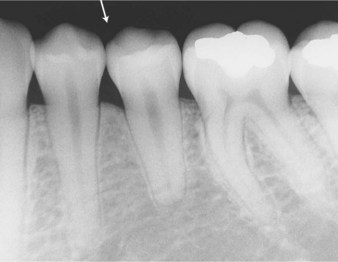
FIGURE 8-1 Air space (arrow) appears radiolucent, or dark, because the dental x-rays pass through freely.
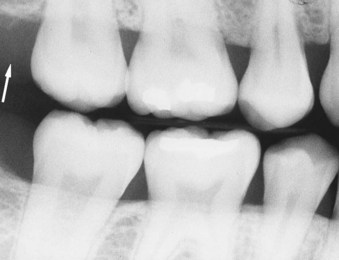
• Radiopaque refers to that portion of a processed radiograph that appears light or white. Radiopaque structures are dense and absorb or resist the passage of the x-ray beam. For example, structures that resist the passage of the x-ray beam include enamel, dentin, and bone and appear radiopaque on a dental radiograph (Figure 8-2).
The ideal dental radiograph is not too light and not too dark. The quality of a dental radiograph is determined by its image characteristics. The image characteristics of a dental radiograph include the visual characteristics of proper density and contrast as well as the geometric characteristics of sharpness with minimal magnification and distortion. The ideal dental radiograph is a diagnostic one. A diagnostic radiograph provides a great deal of information; the images exhibit proper density and contrast, have sharp outlines, and are of the same shape and size as the object radiographed.
Visual Characteristics
Two visual characteristics of the radiographic image—density and contrast—directly influence the diagnostic quality of a dental radiograph.
Density
The overall blackness or darkness of a dental radiograph is termed density.
Description
When a dental radiograph is viewed against a light source, the relative transparency of areas on the radiograph depends on the distribution of black silver particles in the emulsion. Darker areas represent heavier deposits of black silver particles. Density is this degree of silver blackening.
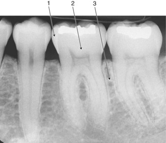
Images of teeth and supporting structures must have enough density to be viewed on a light source; however, if the density of an image is too great, or the image appears too dark, images that cannot be visually separated from each other may result. A radiograph with the correct density enables the radiographer to view black areas (air spaces), white areas (enamel, dentin, and bone), and gray areas (soft tissue) (Figure 8-3).
Influencing Factors
A number of factors have a direct influence on the density of a dental radiograph. As discussed in Chapter 3, three exposure factors control the density of a dental radiograph, as follows:
Any increase in such exposure factors, separately or combined, increases the density of a dental radiograph. In addition, the thickness of the subject influences density (Table 8-1).
TABLE 8-1
Visual Characteristics and Influencing Factors
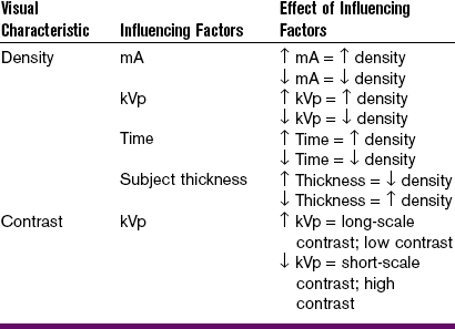
mA, milliamperage; kVp, kilovoltage peak; ↑, increased; ↓, decreased.
Milliamperage: Today, most modern dental x-ray machines do not allow for the adjustment of milliamperage (mA). In machines that do allow for adjustment, an increase in mA produces more x-rays that the receptor is exposed to and, as a result, increases density. If the milliamperage is increased, the density increases, and the radiograph appears darker. Conversely, if the milliamperage is decreased, the density decreases, and the radiograph appears lighter.
Operating Kilovoltage Peak: Today, many modern dental x-ray machines do not allow for the adjustment of operating kilovoltage peak (kVp). An increase in kVp increases density by increasing the average energy of the x-rays and by producing x-rays of higher energy. If the operating kilovoltage is increased, the density increases, and the radiograph appears darker. Conversely, if kilovoltage is decreased, the density decreases, and the radiograph appears lighter.
The kVp has been compared to a spray nozzle on a garden hose. Like the spray nozzle, the kVp controls the force of the emerging x-rays. Low kVp is like “opening up” the nozzle on a hose. The x-rays have less power and do not penetrate well. As a result, the image is mostly black and white. High kVp is like “closing down” the spray nozzle on a hose. The beam is highly penetrating and has high energy. As a result, many shades of gray are seen in the resultant image.
Although using a high kVp produces more x-rays, a linear relationship does not exist. For every increase of 15 kVp, a two-time increase in density occurs.
Exposure Time: Density is directly related to exposure time. An increase in exposure time increases density by increasing the total number of x-rays that reach the receptor surface. If the exposure time is increased, more x-rays reach the receptor, the density increases, and the radiograph appears dark. Conversely, if the exposure time is decreased, the density decreases, and the radiograph appears lighter.
The x-ray timer has been compared to a water faucet. It turns the flow of x-rays on or off. For example, if the faucet is open for a certain period, a specific amount of water will flow. If the faucet is opened for twice that amount of time, twice the amount of water will flow. The same is true with exposure time. If a receptor is exposed to x-radiation for a specific period, a specific amount of x-ray photons will come out of the machine. If the time is doubled, the amount of x-rays produced is doubled. The longer the exposure time, the more x-ray photons reach the receptor, expose it, and continue to darken the image.
Subject Thickness: Fewer x-rays reach the receptor in a patient with an increased amount of soft tissue or thick, dense bones. As a result, the image has less density and appears lighter. Adjustments in operating kVp, mA, or exposure time can be made to compensate for variations in the size of patients and subject thickness.
Contrast
The difference in the degrees of blackness (densities) between adjacent areas on a dental radiograph is termed contrast.
Description
The differences in the amount of light transmitted through adjacent areas of a dental radiograph can also be described as contrast. When viewed on a light source, a dental radiograph that has very dark areas and very light areas is said to have high contrast; the dark and light areas are strikingly different. A radiograph that does not have very dark and very light areas but instead has many shades of gray is said to have low contrast. In dental radiography, an image that is a compromise between low contrast and high contrast is preferred. The overall contrast of a dental radiograph is determined by the properties, or film contrast, and by the object radiographed, or subject contrast.
Film Contrast: Film contrast refers to the characteristics of the receptor that influence radiographic contrast. The characteristics that influence contrast include the inherent qualities of the film and film processing, and the qualities of the sensor. The inherent qualities of the film are under the control of the film manufacturer and cannot be changed by the dental radiographer. Film processing, however, is under the control of the dental radiographer. Development time or the temperature of the developer solution affects the contrast of a dental radiograph. An increase in development time or developer temperature results in a film with increased contrast.
Subject Contrast: Subject contrast refers to the characteristics of the subject that influence radiographic contrast. Subject contrast is determined by the thickness, density, and composition (atomic number) of the subject. Subject contrast can be altered by increasing or decreasing the kilovoltage. When a high operating kVp (0.90 kVp) is used, low subject contrast results, and many shades of gray are seen on the dental radiograph. Conversely, when a low operating kVp (65–70 kVp) is used, high subject contrast results, and areas of black and white are seen.
Influencing Factors
Only one exposure factor has a direct influence on the contrast of a dental radiograph. As discussed in Chapter 3, the operating kVp affects contrast.
Operating Kilovoltage Peak: Increasing the kilovoltage affects contrast by increasing the average energy of the x-rays and by producing higher energy x-rays. X-rays with higher energy are better able to penetrate tissue. As a result, more variations in tissue density are recorded on the receptor and appear as varying shades of gray. A higher kilovoltage produces an image with decreased or low contrast; the radiograph exhibits many shades of gray. Conversely, a lower kilovoltage produces an image with increased or high contrast; the radiograph has many black-and-white areas.
Table 8-1 summarizes the effects of kilovoltage on contrast. Figure 8-4 provides a series of dental radiographs showing the influence of kilovoltage on both density and contrast.
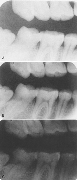
FIGURE 8-4 Exposure series showing the influence of operating kilovoltage peak (kVp). A, When kVp is low, the result is low density (the degree of blackness created by developed silver) and high contrast (the relative difference between the lightest and darkest elements in a radiograph). B, The optimal image is created when a proper balance between kVp and milliamperage (mA) is obtained. This image is considered optimal because it provides a full range of tones from white to black. C, When kVp is high, the result is very high density with very little contrast. (Courtesy Carestream Health, Inc., Rochester, NY.)
Scales of Contrast
The range of useful densities seen on a dental radiograph is termed the scale of contrast. In dental radiography, the terms short-scale contrast and long-scale contrast may be used to describe the appearance of a radiograph.
Short-Scale Contrast: A dental radiograph that shows only two densities, areas of black and areas of white, has a short contrast scale. A lower kilovoltage range results in a radiograph with a short-scale contrast; many areas of black and white, rather than shades of gray, are seen. A radiograph that exhibits a short contrast scale can also be described as having high contrast, in which the black and white areas are easily distinguished from each other (Table 8-2).

Long-Scale Contrast: A dental radiograph that exhibits many densities, or many shades of gray, has a long contrast scale. A higher kilovoltage range results in a radiograph with a long-scale contrast; many shades of gray, rather than areas of black and white, are present. A radiograph that exhibits a long contrast scale can also be described as having low contrast, in which areas of gray are not easily distinguished from each other (see Table 8-2).
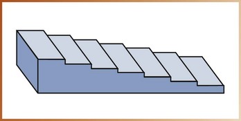
Stepwedge: A device known as a stepwedge can be used to demonstrate short-scale contrast and long-scale contrast. A stepwedge consists of uniform-layered thicknesses of an x-ray absorbing material, usually aluminum. The typical stepwedge is constructed of aluminum steps in 2-mm increments (Figure 8-5). When a stepwedge is placed on top of an image receptor and exposed to x-rays, the different steps absorb varying amounts of x-rays. As a result, different densities appear on the dental radiograph.
The use of a stepwedge to demonstrate corresponding densities and contrast scales is illustrated in Figure 8-6. The stepwedge can be used to monitor the qualities of the film, the film processing, and the sensor; quality control tests using the stepwedge are discussed in Chapter 10.
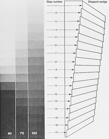
FIGURE 8-6 Radiographs taken at 40 kVp are predominantly black and white; that is, they have high contrast (a short-contrast scale). Those taken at 100 kVp show many shades of gray (a long-contrast scale). (From Miles DA, Van Dis ML, Jensen CW: Radiographic imaging for the dental team, ed 3, St Louis, 2009, Saunders.)
Geometric Characteristics
Three geometric characteristics of the radiographic image—sharpness, magnification, and distortion—influence the diagnostic quality of a dental radiograph. These geometric characteristics must be minimized to produce an accurate radiographic image.
Sharpness
Sharpness (also known as detail, resolution, or definition) refers to the capability of the receptor to reproduce the distinct outlines of an object. In other words, sharpness refers to how well the smallest details of an object are reproduced on a dental radiograph.
Description
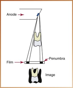
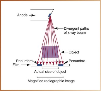
A certain lack of image sharpness, or unsharpness, is present in every dental image. The fuzzy, unclear area that surrounds a radiographic image is termed the penumbra (from the Latin pene, meaning “almost,” and umbra, meaning “shadow”). Penumbra can be defined as the unsharpness, or blurring, of the edges of a radiographic image.
Influencing Factors
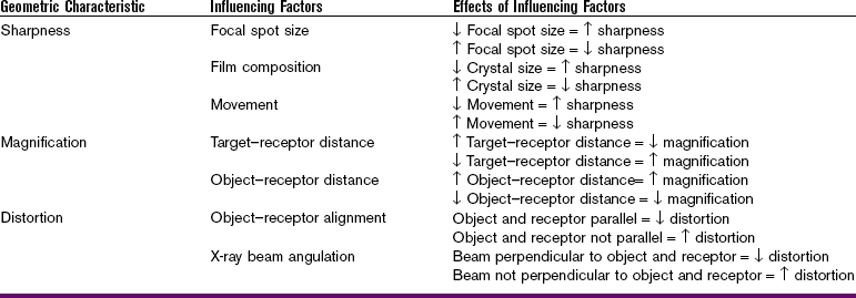
The sharpness of an image is influenced by the following three factors (Table 8-3):
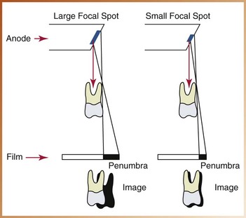
Focal Spot Size: As described in Chapter 2, the tungsten target of the anode serves as a focal spot; this small area converts bombarding electrons into x-ray photons. The focal spot concentrates the electrons and creates an enormous amount of heat. To limit the amount of heat produced and to prevent damage to the x-ray tube, the size of the focal spot is limited. The size of the focal spot ranges from 0.6 to 1.0 mm2 and is determined by the manufacturer of the x-ray equipment; most manufacturers use the smallest focal spot area possible based on heat production restrictions.
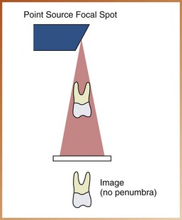
The smaller the focal spot area, the sharper the image appears; the larger the focal spot area, the greater is the loss of image sharpness (Figure 8-7). If x-rays were produced from one spot or a single “point source,” no unsharpness would be present (Figure 8-8). However, a single point source of x-ray production is impossible because of the limited capacity of the x-ray tube.
Film Composition: The composition of the film emulsion influences sharpness. Sharpness is relative to the size of the crystals found in the film emulsion. The emulsion of faster film contains larger crystals that produce less image sharpness, whereas slower film contains smaller crystals that produce more image sharpness. Unsharpness occurs because the larger crystals do not produce object outlines as well as smaller crystals do.
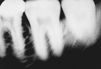
Movement: Movement influences image sharpness. A loss of image sharpness occurs if the tubehead, the receptor, or the patient moves during x-ray exposure (Figure 8-9). Even slight amounts of movement result in unsharpness (Figure 8-10).
Magnification
Image magnification refers to a radiographic image that appears larger than the actual size of the object it represents.
Description
Magnification, or enlargement of a radiographic image, results from the divergent paths of the x-ray beam. As you may recall from Chapter 2, x-rays travel in diverging straight lines as they radiate from the focal spot. Because of these diverging paths, some degree of image magnification is present in every dental radiograph (Figure 8-11).
Influencing Factors
The image magnification on a dental radiograph is influenced by the following (see Table 8-3):
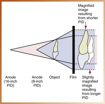
Target-Receptor Distance: As defined in Chapter 3, the target-receptor distance (also known as the source-to-receptor distance) is the distance between the source of x-rays (focal spot on the tungsten target) and the image receptor. The target–receptor distance is determined by the length of the position-indicating device (PID). When a longer PID is used, more parallel rays from the middle of the x-ray beam strike the object rather than the diverging x-rays from the periphery of the beam. As a result, a longer PID and target–receptor distance result in less image magnification, and a shorter PID and target–receptor distance result in more image magnification (Figure 8-12).
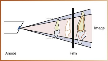
Object–Receptor Distance: The object–receptor distance is the distance between the object being radiographed (the tooth) and the image receptor. The tooth and the receptor should always be placed as close together as possible. The closer the tooth is to the receptor, the less is the enlargement of the image. A decrease in object–receptor distance results in a decrease in magnification, and an increase in object–receptor distance results in an increase in image magnification (Figure 8-13).
Distortion
Dimensional distortion of a radiographic image is a variation in the true size and shape of the object being radiographed. A distorted image does not have the same size and shape as the object being radiographed.
Description
A distorted image results from the unequal magnification of different parts of the same object. Distortion results from improper receptor alignment or beam angulation.
Influencing Factors
The dimensional distortion of a radiographic image is influenced by the following (see Table 8-3):
Object–Film Alignment: To minimize dimensional distortion, the object and receptor must be parallel to each other. If the object (tooth) and receptor are not parallel, an angular relationship results. An angular relationship produces a variation of distances between the tooth and the receptor that result in a distorted image. A distorted image may appear too long or too short (Figure 8-14). Such distortions are discussed in the later chapters on technique.
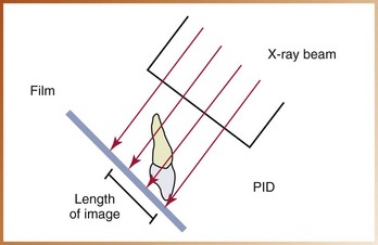
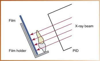
X-Ray Beam Angulation: To minimize dimensional distortion, the x-ray beam must be directed perpendicular to the tooth and the receptor. The central ray of the x-ray beam must be as nearly perpendicular to the tooth and receptor as possible to record the adjacent structures in their true spatial relationships (Figure 8-15).
Summary
• A number of factors influence the visual image characteristics of density and contrast as well as the geometric characteristics of sharpness, magnification, and distortion.
• Milliamperage, operating kilovoltage peak, and exposure time can be used to adjust the density of a dental radiograph. Subject thickness also influences the density of an image.
• Only the operating kilovoltage peak has a direct influence on contrast.
• A radiograph that exhibits areas of black and white is termed high contrast and is said to have a short contrast scale; a radiograph that exhibits many shades of gray is termed low contrast and is said to have a long contrast scale.
• A stepwedge can be used to demonstrate short-scale and long-scale contrast patterns.
• The factors that influence the geometric characteristics of sharpness, magnification, and distortion are reviewed in Table 8-3.
• To create a sharp image, the dental radiographer uses the smallest focal spot possible, chooses a film with small crystals in the emulsion, and limits patient, tubehead, and image receptor movements.
• To limit image magnification, the longest target–receptor distance and the shortest object–receptor distance are used.
• To limit image distortion, the receptor and the tooth are positioned parallel to each other, and the x-ray beam is directed perpendicular to the tooth and the receptor.
Frommer, HH, Savage-Stabulas, JJ, Image formation. Radiology for the dental professional, ed 9, St Louis, Mosby, 2011.
Frommer, HH, Savage-Stabulas, JJ, Image receptors. Radiology for the dental professional, ed 9, St Louis, Mosby, 2011.
Johnson, ON, Thomson, EM, Producing quality radiographs. Essentials of dental radiography for dental assistants and hygienists, ed 8, Pearson, Upper Saddle River, NJ, 2007.
Miles, DA, Van Dis, ML, Jensen, CW, Ferretti, A, Image characteristics. Radiographic imaging for the dental team, ed 4, St Louis, Saunders, 2009.
White, SC, Pharoah, MJ, X-ray film, intensifying screens, and grids. Oral radiology: principles and interpretation, ed 6, St Louis, Mosby, 2009.
Multiple Choice
________ 1. The portion of a processed radiograph that appears dark or black is termed:
________ 2. The portion of a processed radiograph that appears light or white is termed:
________ 3. Which of the following appears most radiolucent on a dental radiograph?
________ 4. An example of a radiopaque structure seen on dental x-rays is:
________ 5. The overall blackness or darkness of a dental radiograph is termed:
________ 6. Increasing the milliamperage (mA) will cause:
a. an increase in density; the image appears darker
b. an increase in density; the image appears lighter
________ 7. Increasing the operating kilovoltage peak (kVp) will cause:
a. an increase in density; the image appears darker
b. an increase in density; the image appears lighter
________ 8. Increasing the exposure time will cause:
a. an increase in density; the image appears darker
b. an increase in density; the image appears lighter
________ 9. A dental patient has thick soft tissues and dense bones. To compensate for this increase in subject thickness and to provide an image of diagnostic density, the dental radiographer may:
________ 10. The difference in the degrees of blackness between adjacent areas on a dental radiograph is termed:
________ 11. When viewed on a light source, a dental radiograph that demonstrates many shades of gray is said to have:
________ 12. When viewed on a light source, a dental radiograph that demonstrates very dark areas and very light areas is said to have:
For questions 13 to 17, refer to Figure 8-16.

FIGURE 8-16
________ 13. In Figure 8-16, which diagram exhibits high contrast?
________ 14. In Figure 8-16, which diagram exhibits low contrast?
________ 15. In Figure 8-16, which diagram exhibits long-scale contrast?
________ 16. In Figure 8-16, which diagram exhibits short-scale contrast?
________ 17. In Figure 8-16, which diagram exhibits no contrast?
________ 18. The one exposure factor that has a direct influence on the contrast of a dental radiograph is:
________ 19. The type of contrast preferred in dental radiography is:
________ 20. The stepwedge is used for all of the following except:
a. to demonstrate short-scale and long-scale contrast
b. to monitor quality control of film processing
________ 21. The capability of the receptor to reproduce distinct outlines of an object is termed:
________ 22. The unsharpness or blurred edges seen on a radiographic image is termed:
________ 23. The geometric characteristic that refers to a radiographic image that appears larger than its actual size is termed:
________ 24. A variation in the true size and shape of the object being radiographed is termed:
Fill in the Blank
For questions 25 to 35, fill in the blank with the words increase or decrease.
25. Decrease focal spot size = __________ sharpness.
26. Increase crystal size = __________ sharpness.
27. Decrease crystal size = __________ sharpness.
28. Decrease movement = __________ sharpness.
29. Increase movement = __________ sharpness.
30. Increase target–receptor distance = __________ magnification.
31. Increase object–receptor distance = __________ magnification.
32. Decrease object–receptor distance = __________ magnification.
33. Object and receptor are parallel = __________ distortion.
34. Beam perpendicular to object and receptor = __________ distortion.
35. Beam not perpendicular to object and receptor = __________ distortion.