Chapter 8 Magnetism
Chapter contents
8.1 Aim
In this chapter the key principles of magnetism are considered. Magnetism plays a vital role in the scanning technique called magnetic resonance imaging (MRI), which uses powerful magnetic fields to portray human tissues.
8.2 Magnetic fields
As long ago as the 11th century, the Chinese were employing magnetic compasses. These consisted of a length of permanently magnetized iron which will tend to align itself in the direction of the Earth’s magnetic field when free to pivot. The phenomenon that two like magnetic poles (such as two north poles) repel and two unlike magnetic poles (such as a north and a south pole) attract was demonstrated by Peter Peregrinus in the 13th century.
Whenever an electrical charge is in motion, a magnetic field is produced. This takes place when electrons flow in a conductor such as a metal wire. There are also electron orbital motions and spins in atoms, which produce tiny magnetic fields.
Whenever a field is produced in a volume of space, an energy gradient exists. In other words there is a change of energy within that volume. The energy gradient means that force may be exerted on a charge present within the field. For example, force may be exerted on a current-carrying wire, on a compass needle which experiences a twisting force, or on the magnetic spins of nuclei within the field of an MRI magnet. Materials which are capable of being temporarily magnetized experience a force when placed in a magnetic field. A vivid demonstration of this effect (not to be attempted!) is the sight of an object such as a pair of scissors accelerating through the air towards the bore of an MRI magnet. This is an example of the ‘projectile effect’ in which a magnetic field exerts a ‘torque’ (or twisting force) on a ferromagnetic object such as iron, tending to align it with the field and bring it closer to the strongest point in the field.
A magnetic north and magnetic south pole separated by a distance is known as a magnetic dipole. A dipole can comprise the two poles of a permanent magnet or the two ends of a current-carrying loop of conductor. If two magnetic poles of strength p are separated by a distance l, then the magnetic dipole moment of the system, m=p×l.
The force F between two magnetic poles is equal to the product of their individual strengths divided by the square of the distance between them.
F is proportional to (p1×p2) divided by d2, where p1 and p2 are the individual magnetic pole strengths and d2 is the square of the distance between them. Thus it can be seen that the force on an object entering a magnetic scanner room increases greatly as the distance to the scanner decreases. This is an example of an ‘inverse square law’. Further examples of the law, which is particularly important in radiography, are provided in Chapter 26.
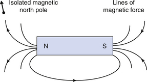
The direction of a magnetic field is taken as the direction in which a hypothetical isolated magnetic north pole would move if placed in the field. Hence lines of magnetic field pass from the north to the south pole of a permanent magnet, as shown in Figure 8.1 (see page 50).
It isn’t correct to talk about the north and south poles of an MRI scanner. Such scanners produce a very powerful magnetic field in the z-axis (or long axis) of a patient lying within the scanner, and we can talk about a ‘spin-up’ orientation parallel to the field and a ‘spin-down’ orientation antiparallel to it. But the concept of an MRI scanner as a large bar magnet is misleading.
The field around a bar magnet is non-uniform, that is it varies in strength and direction with location. In contrast, the Earth’s magnetic field is relatively uniform and the magnetic field lines run fairly parallel to each other. Although this is generally true, there may be small local variations due to the presence of iron-containing rock. The Earth’s magnetic flux density is typically about 0.5 gauss (G) or 0.5 × 10⁻⁴ tesla. A tesla equals 10 000 gauss. The gauss is an old centimetre gram second (cgs) unit but is still in common use as it is sometimes easier to use. For example, it is easier to talk about a ‘5-gauss exclusion zone’ surrounding an MRI scanner than a 0.0005 tesla zone! The larger and more current SI unit of tesla (T) for magnetic flux density and magnetic inductance is used a lot to describe the ‘field strength’ of MRI scanners, where 0.2 T would be regarded as a ‘low field’ magnet and 3 T as a ‘high field’ magnet. A 3-T magnet provides a magnetic field about 60 000 times more powerful than that of the Earth.
Note: although the tesla is commonly used to describe the ‘strength’ of the magnetic field B in radiography, strictly the tesla is a unit of magnetic flux density or inductance.
The static (or constant) magnetic field produced by an MRI magnet needs to be as uniform as possible within the bore itself, in order to maximize image quality. Magnetic field homogeneity needs to be achieved, with a maximum permissible variation of 1 part in 100,000 for clinical MR imaging and to about 1 part in 10 million for in-vivo (living) magnetic resonance spectroscopy, which produces spectral signatures of chemicals present in the body. In practice, small inhomogeneities (non-uniformities) arise when an object such as a patient is present within the magnetic field.
There are two contributions to the magnetic moment of an electron, namely an orbital magnetic moment due to angular momentum around the nucleus, and a spin magnetic moment due to spin about the electron’s own axis. The permitted spins of an electron are +1/2 and −1/2. Paired electrons within full orbitals have opposing spins and cancel out each other’s magnetic moments. Likewise, the net magnetic moment of a filled electron shell is zero, since all the orbitals within it are full. Only the unfilled electron shell needs to be considered when examining magnetic properties. Contributions to the spin and angular momentum for each individual outer shell electron need to be added vectorially.
Paramagnetic materials have a small positive magnetic susceptibility, symbol χ, of the order of +10−3 to +10−5. The magnetic susceptibility of a material refers to the extent to which it can become temporarily magnetized in a magnetic field. Materials with positive susceptibility reinforce the effect of a magnetic field. The magnetization of paramagnets is weak but parallel to the direction of the applied magnetic field. These materials usually have unpaired electrons. They include atoms and ions of transition elements, rare Earth elements, some metals, oxygen and free radicals. Examples are aluminium, platinum, manganese and the ion Gd3+, which is used within MRI contrast agents to reduce MRI T1 relaxation times and hence brighten the signal. Fe2+ ions in the liver, bound to organic molecules, also reduce T1 times. See Chapter 39 for an explanation of the T1 process.
Diamagnetic materials have a small negative magnetic susceptibility, of the order of 10−5. Their magnetic response is in opposition to the applied magnetic field. These materials, such as copper, silver, gold, bismuth and beryllium, have filled electron shells and no net magnetic moment. Their induced magnetization opposes the magnetic field, in a manner predicted by Lenz’s law. The applications of Lenz’s law are covered in Chapter 10.
Ferromagnetic materials have a very high positive magnetic susceptibility of the order of +50 to +10 000. Ferromagnetic materials retain their magnetization once exposed to a magnetic field. They are used within permanent MRI magnets. The disadvantage of such magnets is their low maximum field strength. The property of ferromagnetism is due to the bulk effects of many electrons within the material, rather than to the magnetic effects of the electrons within individual atoms. Examples are iron, cobalt and nickel.
Superparamagnetic materials exhibit a large positive magnetic susceptibility. They differ from ferromagnetic materials in consisting of small size particles which do not display the bulk properties of ferromagnetic materials. They become transiently magnetized within a magnetic field. An example is coated particles of iron oxide, used as a negative contrast agent which reduces MRI T2 times and reduces signal intensity.
The magnetic susceptibility properties of body tissues can be used in MRI to provide useful signal information. For example, the magnetic susceptibility of liver and haemorrhage is altered by their iron content. Metallic implants often produce a large magnetic susceptibility artefact in MRI, by distorting the local magnetic field. The magnetic susceptibilities of oxygenated and deoxygenated blood differ and this can be used in functional MRI of tissue blood supply
So far we have only considered the magnetic effects due to electrons. However, there is a small contribution to the total angular momentum of the atom from the nucleus, due to its spin. This contribution is about one-thousandth of that of an electron, but is a very important property in MRI.
Nuclei, like electrons, possess ground energy levels and excited energy levels. Protons and neutrons, the constituents of nuclei, have a spin quantum number of +1/2 or −1/2. They also have orbital angular momentum by virtue of their motion in the nucleus. Both the proton and the neutron possess a magnetic moment (the latter despite not having an overall electrical charge, for reasons which need not concern us here). The sum total of the spin and orbital angular moments of the nucleons in the nucleus is referred to as the nuclear spin. Since an odd number of spin 1/2 particles always combine to give a half integer total spin, it follows that nuclei with an odd mass number have nuclear spins of values 1/2, 3/2, 5/2, etc. It is these nuclei that concern us in MRI and have useful magnetic spins. The most important one is the hydrogen-1 nucleus, which is just a single proton and has a 1/2 spin. Phosphorus-31 is used in MR spectroscopy. Note that the individual nucleon spins are cancelled out in nuclei with even mass numbers and thus these nuclei are of no use to us in MRI.
MRI used to be termed nuclear magnetic resonance, because it depends upon the magnetization of the atomic nucleus. The name was changed because the public tended to confuse it with the nuclear reactions, involving the fission of atomic nuclei, that occur in power stations and atom bombs.
We commented earlier that the magnetic moment of an electron is much greater than that of a nucleus. Indeed, electron spin resonance has been studied to examine its potential for imaging. However, electron spin resonance occurs on the gigahertz or GHz frequency range, and leads to considerable heating of tissues. In addition, these frequencies are absorbed superficially in the body, leading to poor deep imaging.
8.3 Bulk magnetic properties and permanent magnets
We saw above that some elements and materials like iron are highly magnetic (ferromagnetic) while others like gold, plastics and most body tissues have almost no magnetization. A ferromagnetic material like a block of iron in fact consists of many tiny crystals, not just one slab of homogeneous material. These small crystals can be considered as individual domains, each with an overall magnetization in a particular direction. If the domains are aligned randomly, very little overall magnetization will result, although the domains may become more aligned in the presence of a strong magnetic field, producing temporary magnetization. This is the case when a pair of scissors hurtles into an MRI magnet!
In permanent magnets, the domains tend to align in a particular direction and are fixed in this direction, giving a permanent overall magnetization, as shown in Figure 8.2.
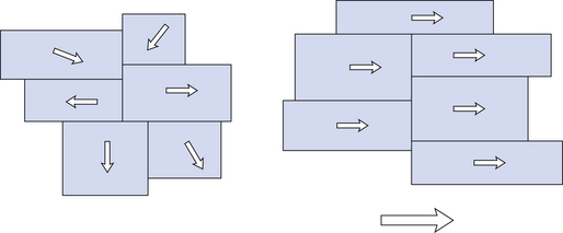
Figure 8.2 Individual magnetic domains are randomly aligned (but can be influenced) in non-permanent magnetic materials (left) while permanent magnets (right) have their domains in fixed alignment, giving an overall magnetization.
A small number of MRI scanners employ permanent magnets to produce a magnetic field. These magnets have the disadvantages of being bulky and producing a relatively low magnetic field strength. More will be said about the types of available MRI scanners in Chapter 39. There have been improvements in the technology of permanent magnets and a range of materials, such as neodymium iron, ceramics, ferrites and rare Earth elements can be employed in their construction.
In this chapter you should have learnt the following:
• Magnetic properties exist in nuclei and electrons at the atomic level (see Sect. 8.3) and also in whole materials at the macroscopic level (see Sect. 8.4).
• Magnetism may be temporary or permanent and many materials become magnetized within a magnetic field (see Sect. 8.4).
• There are many applications of these principles in magnetic resonance imaging and general radiography.