Chapter 10 Electromagnetic induction
Chapter contents
10.1 Aim 57
10.2 Introduction 57
10.3 Conditions necessary for electromagnetic induction 57
10.4 Faraday’s laws of electromagnetic induction 58
10.5 Lenz’s law 58
10.6 Sign convention for the induced current 59
10.7 Mutual induction 59
10.8 Self-induction 60
10.9 The AC generator 61
Further reading 62
10.1 Aim
This chapter considers the laws of electromagnetic induction. The direction of the induced current will be identified. The concepts of mutual induction and self-induction will be discussed in preparation for Chapter 14, where the application of these will be considered in transformer design.
10.2 Introduction
In Chapter 9, we covered the topic of electromagnetism and this chapter deals with the topic of electromagnetic induction. As can be seen from the definitions below, one is just the reverse of the other. They may each be defined as follows:
Electromagnetism is the production of a magnetic field by the passage of an electrical current (see Ch. 9).
Electromagnetic induction is the production of electricity by the interlinking of a conductor with a changing magnetic field, or moving a conductor relative to a stationary magnetic field (also known as the generator effect).
10.3 Conditions necessary for electromagnetic induction
Consider the simple experiment depicted in Figure 10.1. A solenoid L is joined to a meter that can measure both the magnitude and the direction of the current flowing through the solenoid. The following effects are observed:
• No current flow is observed on the meter if the magnet is stationary with respect to the solenoid (Figure 10.1A and C).
• A current flows through the meter whenever the magnet is moved towards or away from the solenoid (Figure 10.1B and D).
• The magnitude of the induced current is greater if the magnet is moved faster.
• Reversing the direction of the movement of the magnet reverses the direction of the induced current (Figure 10.1B and D).
• Reversing the pole of the magnet, which is closer to the solenoid, reverses the direction of the induced current for a given movement.
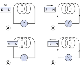
Figure 10.1 An example of electromagnetic induction. A current flows only when there is relative movement between the bar magnet (M) and the solenoid (L).
From this simple experiment, we can conclude that only a changing magnetic field relative to the conductor is able to induce electricity in the conductor. We can also see that the amount of electricity produced is in some way related to the rate of change of the magnetic field relative to the conductor. Finally, we can conclude that the direction of movement of the magnetic field influences the direction of the induced current. These concepts will be discussed in more detail in the following sections of this chapter.
10.4 Faraday’s laws of electromagnetic induction
Faraday produced two laws of electromagnetic induction that cover some of the observations we made in the previous section. These may be defined as follows:
1. A change in the magnetic flux linked with a conductor induces an electromotive force (EMF) in the conductor.
2. The magnitude of the induced EMF is proportional to the rate of change of the magnetic flux linkage.
In order to understand Faraday’s laws, we need to have a clear understanding of EMF and magnetic flux linkage.
EMF was considered in Section 7.6 and can be considered as the force which is capable of causing electrons to flow (i.e. EMF will cause a current to flow in a complete circuit). It is important to note that Faraday’s laws do not specify whether or not the conductor is connected to an external circuit but, in either case, an EMF will be induced in it.
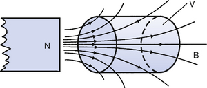
Magnetic flux and magnetic flux density are discussed in Chapters 8 and 39. The magnetic flux through a volume V can be visualized as being proportional to the number of lines of flux passing through that volume (Fig. 10.2). Thus, if a magnetic flux of 10 weber passes through V, then the magnetic flux linkage with V is also said to be 10 weber. If the magnet in Figure 10.2 is moved to the left of the page, then the number of lines of flux (or the flux linkage) in the volume V will be reduced.
We now see that moving the magnet relative to the solenoid will alter the flux linkage between the magnet and the solenoid and so an EMF will be induced – Faraday’s first law. Also, a rapid movement of the magnet increases the rate of change of flux linkage and so increases the size of the induced EMF – Faraday’s second law.
Changing the magnetic flux linkage associated with a particular conductor may be achieved in two ways:
1. By moving the conductor relative to a stationary magnet – this principle is used in the alternating current (AC) generator or dynamo (Sect. 10.9).
2. By varying the magnitude of the magnetic flux while the conductor is stationary – this principle is used in the AC transformer (see Ch. 14).
10.5 Lenz’s law
In our initial observations regarding the induced current (Sect. 10.3) we noted the direction as well as the size of the current. Faraday’s laws apply to open or closed circuits but, as Lenz’s law concerns the direction of the induced current, it can only be applied to closed circuits. The law can be stated as follows:
The direction of the induced current in a conductor caused by a changing magnetic flux is such that its own magnetic field opposes the changing magnetic flux.
Lenz’s law is an example of the application of the law of conservation of energy (Sect. 3.3). If the direction of the induced current was such that its magnetic field helped the changing magnetic field, then we would be getting something for nothing so we could establish perpetual motion of the conductor and the magnetic field. This would be in defiance of the law of conversation of energy.
When the north pole of a bar magnet is moved towards a solenoid (Figure 10.1B), the current will flow in the solenoid in such a direction that it produces a north pole at the end closest to the magnet. This has the effect of producing a force of repulsion between the bar magnet and the solenoid and so work must be done against this force in order to keep the magnet moving towards the solenoid. Thus, mechanical energy is transformed to electrical energy and the law of conservation of energy is maintained. The reverse occurs when the magnet is withdrawn.
10.6 Sign convention for the induced current
When current flow was considered as the flow of positive charge, this was determined using Fleming’s right-hand rule. As we now know that current flow is a flow of electrons, Fleming’s hand rules are liable to cause confusion and so the direction of current flow will be determined using the convention shown in Figure 10.3.
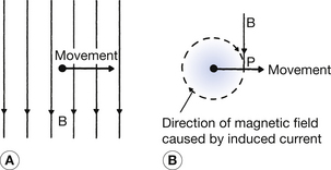
Figure 10.3 An example of the use of the convention described in the text for establishing the direction of the induced current.
Consider a situation similar to that shown in Figure 10.3A. Here a conductor is moved at right angles to a magnetic field (Fig. 10.3B) – the direction of the movement and the direction of the magnetic field are as shown in the diagram. We wish to determine whether the induced electron flow along the conductor will be either into the page or out of the page. This can be determined as follows:
1. Mark the position of the conductor and draw a line to indicate the direction of movement.
2. Draw a second line (B) to represent the permanent magnetic field direction to intersect the first line at the point P (Fig. 10.3B).
3. Now, draw a circle with the conductor at its centre such that its circumference passes through the point P.
4. This circle represents the magnetic field that will be caused by the current induced in the conductor. The direction of this magnetic field is the same as the direction of the permanent magnetic field at the point P – the field is in a clockwise direction.
5. As we learnt in Section 9.4, the magnetic field around a current-carrying conductor is anticlockwise when the electrons are travelling away from us. Thus, because of the clockwise magnetic field, we can conclude that the electrons (of the induced current) are travelling towards us.
10.7 Mutual induction
If a changing current is passed through one conductor, then this will produce a changing magnetic field around this conductor (see Ch. 9). If a second conductor is placed within this changing magnetic field, then (by Faraday’s laws) an EMF will be generated in the conductor and a current will flow in it if the conducting loop is complete (Fig. 10.4).
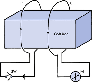
Figure 10.4 Principles of mutual induction. A changing current in coil P (the primary coil) induces a current in coil S (the secondary coil) and vice versa. The soft iron core magnifies the effect by improving the magnetic flux linkage between the coils. M, ammeter; SW, switch.
By Lenz’s law, this current will be in the opposite direction to the original current. The size of this secondary current will vary with the magnetic field – it will be a current of changing magnitude, as there is a changing magnetic field. This changing secondary current will produce its own changing magnetic field, which will induce an EMF and current in the first conductor. Thus, each conductor induces electricity in the other and the effect is known as mutual induction.
Consider Figure 10.4. When the switch, SW, is closed, electrons will flow from the negative pole of the battery to its positive pole via the coil P. During the time while the rate of flow of electrons builds up, there is a changing magnetic field around P. This is linked to S via the iron core (the iron core greatly enhances the flux linkage) and so an EMF and current flow will occur in S. The direction of the pointer on the ammeter, M, indicates that this flow of electrons in S is in the opposite direction to that in P, verifying Lenz’s law. After a short time, the current in P is constant and so S is no longer influenced by a changing magnetic field. As a result, no EMF is generated in S (Faraday’s first law). If the switch, SW, is now opened, the magnetic field around P collapses and so an EMF is again generated in P, but this time it is in the opposite direction. If a more powerful battery is now used, this produces a greater current in P, thus a greater magnetic field and consequently a greater EMF in S (the magnitude of the induced EMF is proportional to the rate of change of the magnetic flux). Finally, if we undertake the experiment with the iron bar present, and then with the iron bar removed, we find that the EMF produced in the coil S is greatest when the iron bar is present. This is because of improved magnetic flux linkage (Faraday’s second law).
From this experiment, we can show that the EMF induced in the secondary winding ES is:
• proportional to the rate of change of the current in P (the primary)
• dependent on the detailed design of the two conductors and the flux linkage between them. This is called the mutual inductance (M).

The greater the mutual inductance, M, the greater the mutual effect between the two conductors. M is measured in henrys, and may be defined as:
10.8 Self-induction
Consider the solenoid in Figure 10.5A. If the switch, SW, is closed, current flow starts to build up in the solenoid. As this current increases, each turn of the solenoid produces a changing magnetic flux, which is linked to the other turns of the solenoid (the flux from one turn is shown in Fig. 10.5A). Thus, from Faraday’s and Lenz’s laws, an EMF in the opposite direction to the EMF from the battery will be induced in the solenoid. This is known as a back-EMF. This effect is known as self-induction and, if the self-induction is large, the current in the coil will take an appreciable time to build up to its maximum value. The self-induction in an electrical system is defined in a very similar manner to the mutual induction and is given by the equation:
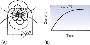
Figure 10.5 Principles of self-induction. The changing magnetic flux produced by the current flow through the solenoid when the switch, SW, is closed links with all the turns of the coil. This produces a back-electromotive force, which slows down the rate of growth of current in the coil.
Here EB is the back-EMF and L is the self-inductance, measured in henrys. Thus, we can say that:
A conductor has a self-inductance of 1 henry if a back-EMF of 1 volt is induced when the current flowing through it changes at 1 ampere per second.
A graph of the current flowing through the solenoid is shown in Figure 10.5B. As can be seen, the induced back-EMF slows down the rate of growth of the current and so it takes an appreciable time to reach its maximum value, determined by Ohm’s law. If the wire of the solenoid were unwound to become a straight conductor, then there would be no magnetic flux linkage and consequently no back-EMF. Thus, the current would rise to its maximum value very quickly.
As in the case of mutual induction, a soft iron bar placed in the solenoid will enhance the self-induction as the magnetic flux linkage between the coils is improved.
10.9 The AC generator
Electric power is produced from an AC generator. This is an example of a situation where mechanical energy is converted to electrical energy. The basic components of such a generator are shown in Figure 10.6A. A permanent magnetic field exists between the poles of the magnet, and coils of copper wire rotate through this field. For simplicity, only one coil is shown in the diagram. The EMF generated in the device is collected at brushes positioned at A and B.
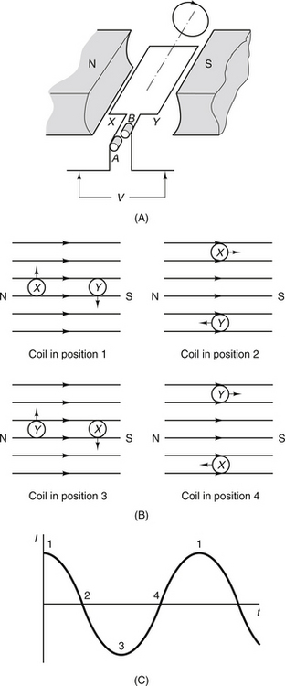
Figure 10.6 (A) Simplified diagram of an alternating current generator; (B) four positions of the coil relative to the magnetic field; (C) the current waveform produced when the coil moves through positions 1, 2, 3, 4 and returns to 1. A complete turn of the coil will produce one cycle of current. See text for further details.
Now consider the situation where the coil shown is rotated in a clockwise direction. Thus, from the initial position, side X of the coil will move upwards through the magnetic field and side Y will move downwards (Fig. 10.6B). At this point in its movement, the coil is cutting the maximum number of lines of flux as it is moving at right angles to the flux lines, and so the maximum EMF will be generated. If we use the convention discussed earlier (see Sect. 10.6) to establish the direction of electron flow, we can see that electrons will travel towards us on side X and away from us on side Y. Thus, an excess of electrons will exist at brush A and a shortage of electrons will exist at brush B: brush A is negative and brush B is positive. This situation is shown as position 1 on the graph in Figure 10.6C. Now consider the situation when the coil has turned in a clockwise direction from its initial position through 90°: this is the second position of the coil shown in Figure 10.6B. In this position, both side X and side Y of the coil are moving parallel with the lines of magnetic flux and so no current is generated – this is again shown as position 2 in Figure 10.6C. In position 3, the coil has rotated through 180° from its original position. Side X of the coil is now moving downwards through the magnetic field and side Y is moving upwards. As in position 1, a maximum number of lines of flux are being cut as the conductor is moving at right angles to the flux, and so, again, the maximum EMF will be generated. The polarity of A and B is now the reverse of position 1. In position 4, the conductor is again moving parallel to the lines of flux so no EMF is generated. The conductor then returns to position 1 and so one cycle is complete. The process is then repeated. The type of current shown in Figure 10.6C is known as AC and will be the subject of Chapter 11.
In cases where there is no external circuit connected, then no current is able to flow and only sufficient work to overcome the frictional resistance is necessary to keep the rotational movement at the same speed. As soon as an external circuit is connected, then a current is able to flow in the circuit and in the winding.
It should come as no surprise to discover that this current will flow in such a direction as to oppose the motion of the coil (remember Lenz’s law). This means that mechanical work must be performed to overcome this resisting force, i.e. mechanical energy is converted into electrical energy.
The effect of suddenly increasing the electrical load demanded from the generator (e.g. when making an X-ray exposure) is suddenly to increase the opposition to its rotation. Hence, the generator slows down momentarily, the induced EMF (which depends on the speed of rotation) is reduced. We find that, in times of increased demand on the generators, there is a drop in the voltage they supply. In X-ray units, this is taken into account by the inclusion of a mains voltage compensator on the unit.
In this chapter you should have learnt the following:
• That an EMF is induced in a conductor if it is linked with a changing magnetic field (see Sect. 10.3).
• Faraday’s first and second law of electromagnetic induction (see Sect. 10.4).
• Lenz’s law, which determines the direction of the current flowing as the result of the induced EMF (see Sect. 10.5).
• The sign convention for the direction of the induced current (see Sect. 10.6).
• The meaning and a simple application of mutual induction (see Sect. 10.7).
• The meaning and a simple application of self-induction (see Sect. 10.8).
• The mode of operation of an AC generator (see Sect. 10.9).
Further reading
Ball J.L., Moore A.D., Turner S. Ball and Moore’s Essential Physics for Radiographers, fourth ed. London: Blackwell Scientific, 2008. (Chapter 9)
Dowsett D.J., Kenny P.A., Johnston R.E. The Physics of Diagnostic Imaging. London: Chapman & Hall Medical, 1998. (Chapter 1)
Ohanian H.C. Principles of Physics. London: W W Norton, 1994. (Chapter 22)
Thompson M.A., Hattaway R.T., Hall J.D., Dowd S.B. Principles of Imaging Science and Protection. London: W B Saunders, 1994. (Chapter 5)