Chapter 24 Luminescence and photostimulation
Chapter contents
24.1 Aim
The aim of this chapter is to introduce the topics of luminescence, fluorescence, phosphorescence, thermoluminescence and photostimulation. In the case of each of the processes, the relevance to radiographic imaging will be briefly discussed.
24.2 Introduction
If we irradiate a material with high-energy photons and this causes the material to emit photons of lower energy, the material is exhibiting the property of luminescence. Within the strict laws of physics, provided that the energy is lower than that of the original radiation beam, the emitted radiation can be in any part of the electromagnetic spectrum. In radiography we are more interested in luminescence when the radiation emitted falls in the visible part of the spectrum. Before we can discuss the process in detail, we need to define some basic terms.
24.3 Luminescence, fluorescence and phosphorescence
As mentioned above, if we irradiate a material and it emits visible light, then that material is said to exhibit luminescence.
Fluorescence occurs when the light emission ceases almost immediately after the irradiation has stopped (the time interval is about 10−8 s), then it can be seen that we require materials that exhibit fluorescence as this allows us to remove the image receptor from the cassette and process it immediately after the X-ray exposure has taken place.
Phosphorescence occurs if the material continues to emit light for a significant time after the initial period of radiation. For this reason, phosphorescence is often referred to as afterglow. Such a phenomenon is generally not desirable in radiography – if we had significant afterglow then we would have to wait before cassettes could be emptied and refilled. Afterglow can also cause image lag in fluoroscopy.
From the above we can say that luminescence occurs when we irradiate a material and the substance produces light. If the production of light ceases within 10−8 s of the end of the irradiation, then the process is one of fluorescence; if it continues beyond this point, then we have phosphorescence.
Fluorescence was first demonstrated in salts of phosphorus and so fluorescent materials in radiography are often referred to as phosphors, even though they contain no traces of phosphorus! Some of the phosphors used in intensifying screens exhibit both fluorescence and phosphorescence. We can encourage fluorescence (and discourage phosphorescence) by the addition of activators to the phosphor material. This will be discussed in the rest of this chapter.
24.3.1 Mechanism of fluorescence
The mechanism of fluorescence can be explained by reference to the electron band theory. Fluorescence is caused by an electron in a high-energy state dropping to a lower-energy state and thereby emitting a quantum of radiation (Fig. 24.1). If the wavelength of the emitted quantum is in the range 400–700 nm, this will form part of the visible spectrum. If we consider a phosphor used in radiography being irradiated with X-ray photons, then the first process necessary is that some of the electrons of the phosphor atoms are involved in photoelectric interactions with the X-ray photons raising the energy of the electrons. As already mentioned, the overall efficiency of a phosphor may be improved by the addition of activators. These impurities encourage the formation of luminescent centres within the phosphor; the efficiency of lanthanum oxybromide will be increased by the addition of terbium as an activator. The activators possess discrete electron energy levels which are different from that of the phosphor crystal and these are used to form the luminescent centre.
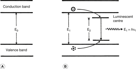
Figure 24.1 Mechanism of fluorescence in a crystal. (A) The outer electron structure of a pure crystal; (B) the effect of an impurity atom on the electron levels. Such impurities enhance fluorescence by forming luminescent centres. These impurities are known as activators. The explanation of the fluorescent process will be found in the text.
This is shown diagrammatically in Figure 24.1. Part A shows the electron energy level arrangement in a pure crystal and part B the arrangement in a crystal with a luminescent centre. These centres will produce fluorescence more efficiently than the pure crystal. The sequence of events occurring within the crystal is as follows:
• An X-ray photon undergoes a photoelectric interaction with an electron of one of the crystal atoms.
• The photoelectric interaction liberates the electron and gives it some kinetic energy so that it is free to move within the conduction band, leaving a ‘hole’ in the valence band.
• The energetic electron, on passing close to other atoms, excites and ionizes these atoms and so more electrons are raised into the conduction band (leaving more holes in the valence band).
• Some of the electrons so liberated will lose small amounts of energy which will allow them to adjust their energy to the energy level of the luminescent centres.
• At the same time, some of the holes in the valence band will have their energy raised to allow them to reach the lower energy level of the luminescent centre.
• Some of the electrons at the upper level of the luminescent centre will perform a quantum jump to neutralize the holes at the lower level of the centre. This is shown diagrammatically in Figure 24.1B where the energy of the emitted photon is El=hv1, where v1 is the frequency of the emitted photon and h is Planck’s constant.
• The difference in energy between the upper and lower levels in the luminescent centre controls the photon energy El and the colour of the emitted (fluorescent) light.
• As more electrons enter the luminescent centres than are involved in the initial photoelectric interactions, the number of fluorescent photons is greater than the number of absorbed photons.
As can be seen from the above, the process of fluorescence occurs as a number of stages and inefficiency at any one stage can affect the efficiency of the whole process. This allows us to compare the operation of different phosphors by comparing efficiency at each of the stages
The quantum detection efficiency (QDE) is a measure of the percentage of the quanta (e.g. X-rays) incident on the phosphor which are stopped by the phosphor.
The quantum conversion efficiency (QCE) is a measure of the percentage of the quantal energy stopped by the phosphor which is converted into light photons.
The scintillation efficiency (ScE) is a measure of the percentage of the quantal energy incident on the phosphor which is converted into useful light photons.
As the ScE is a measure of the overall process, it is affected by changes in the QDE or QCE: if the QDE is 50% and the QCE is 20%, then the ScE will be 10% (ScE=QDE×QCE). These measures of efficiency are shown in Table 24.1 for two phosphors used in radiography.
Table 24.1 Measures of the efficiency of two phosphors used in radiography (the energy of the incident radiation was 60 keV)
| PHOSPHOR | QUANTUM DETECTION EFFICIENCY (%) | QUANTUM CONVERSION EFFICIENCY (%) | SCINTILLATION EFFICIENCY (%) |
|---|---|---|---|
| Calcium tungstate | 13 | 5 | 0.65 |
| Gadolinium oxysulphide | 51 | 20 | 10.2 |
24.3.2 Mechanism of phosphorescence
Phosphorescence is caused by the presence of electron traps within the crystal structure of the phosphor. The mechanism is as follows:
• An X-ray photon undergoes a photoelectric interaction with an electron of one of the crystal atoms.
• The photoelectric interaction liberates the electron and gives it some kinetic energy so that it is free to move within the conduction band, leaving a ‘hole’ in the valence band.
• The energetic electron, on passing close to other atoms, excites and ionizes these atoms and so more electrons are raised into the conduction band (leaving more holes in the valence band).
• Some of the electrons so liberated will lose small amounts of energy which will cause them to fall into the electron traps.
• The electrons remain in the traps until they are released as a result of interatomic vibrations. If the traps are sufficiently near the conduction band, this may happen without the application of additional energy (see trap A in Fig. 24.2).
• Some of these released electrons will find luminescent centres and light will be produced by the process described for fluorescence.
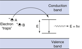
Figure 24.2 The production of phosphorescence and thermoluminescence. An electron enters trap A as a result of energy absorbed from the radiation beam striking the phosphor. After the exposure, this electron can subsequently enter the conduction band as a result of interatomic vibration and hence produce fluorescent photons (phosphorescence) as shown. The electron in trap B will only be released if the material is heated (thermoluminescence), as discussed in the text.
Because there is a measurable length of time when the electron is ‘stuck’ in the electron trap, the luminescence will occur after the irradiation of the material has ceased. This is phosphorescence or afterglow.
The phenomenon diminishes exponentially (see Ch. 20) from the time of cessation of the irradiation. Such a process is generally regarded as a nuisance in radiography, especially for image intensifier and monitor phosphors, since the phosphor may still ‘remember’ the previous image when a new one is being produced.
24.3.3 Mechanism of thermoluminescence
If we refer to Figure 24.2, we can see that trap B is too ‘deep’ below the conduction band for the electrons in it to leave and enter the conduction band. This is a typical arrangement for a thermoluminescent material, e.g. lithium fluoride, as the material contains energy gaps between the valence and conduction bands. The mechanism of thermoluminescence is as follows:
• An X-ray photon undergoes a photoelectric interaction with an electron of one of the crystal atoms.
• The photoelectric interaction liberates the electron and gives it some kinetic energy so that it is free to move within the conduction band, leaving a ‘hole’ in the valence band.
• The energetic electron, on passing close to other atoms, excites and ionizes these atoms and so more electrons are raised into the conduction band (leaving more holes in the valence band).
• Some of the electrons so liberated will lose small amounts of energy which will cause them to fall into the electron traps.
• These electrons get stuck in the traps (see trap B in Fig. 24.2), however the traps are too deep in the forbidden energy gap for normal interatomic vibration to release them. If more energy is applied to the substance by heating it, the electrons will gain energy as a result of the increased interatomic vibrations and can move up into the conduction band.
• Some of these electrons will find luminescent centres and light will be produced by the process described for fluorescence.
• Thus, the intensity of the light emitted from the thermoluminescent material is directly proportional to the amount of radiation incident on the material. This is the basis of thermoluminescent dosimetry, which will be discussed in Chapter 27.
24.3.4 Fluorescent screens in radiography
Fluorescent screens, with film as a recording medium, were once the most common image receptors used in radiography. They have now been replaced by photostimulable plates and other image receptors (see Ch. 34 for more information).
24.3.5 Further examples of fluorescence
Four further examples of fluorescence applicable to radiographic imaging will now be briefly considered (more detailed descriptions may be found in specialist textbooks on X-ray equipment):
1. If we use an image intensifier in fluoroscopy, then this contains an input phosphor and an output phosphor. The input phosphor is usually made of caesium iodide and absorbs X-ray photons and re-emits the energy as light photons. The light photons fall on a photocathode which will emit electrons when bombarded by light. The electrons are accelerated and focused on to an output phosphor where their energy is used to create light photons by the fluorescent effect. The net result of this is that the image is intensified by about 5000 times between the input phosphor and the output phosphor.
2. In the television monitor, the phosphor on the face of the monitor is bombarded by electrons. Such high-energy electrons are capable of causing the phosphor to fluoresce, producing the image on the television monitor.
3. Scintillation counters made of sodium iodide crystals coupled with photomultiplier tubes or solid-state devices can be used to detect small amounts of X-rays and gamma-rays. The intensity of the fluorescence from the crystals is proportional to the intensity of the radiation hitting the crystal. Such devices are used in nuclear medicine, computed tomographic scanners and osteoporosis scanners
4. Radiographic departments are lit by fluorescent lighting. An electrical discharge in the gas in the tube causes the emission of ultraviolet radiation. This is absorbed by a suitable phosphor coated onto the inside of the tubes which then emits visible light.
24.4 Photostimulation
Photostimulated luminescence is said to have been discovered in the mid 19th century by Becquerel, but its practical application was not developed until the early 1970s.
The basic structure of a photostimulable plate is shown in Figure 24.3. The process of photostimulation is very similar to the process of thermoluminescence (Sect 24.3.3). A suitable phosphor (e.g. europium activated barium fluorohalide (BaF(BrI):Eu2)) is irradiated and the following process takes place:
• An X-ray photon undergoes a photoelectric interaction with an electron of one of the phosphor atoms.
• The interaction liberates an electron, giving it kinetic energy so that it is free to move to the conduction band, leaving a ‘hole’ in the valence band.
• The energetic electron, on passing close to other atoms, excites and ionizes these atoms, liberating more electrons and raising them into the conduction band and leaving more holes in the valence band.
• A few electrons with sufficient energy find luminescent centres and light in the blue–green range (550 nm) of the spectrum will be produced by the process described for fluorescence.
• The majority of the liberated electrons lose small amounts of energy, causing them to fall into the electron traps (also called colour centres) in the forbidden gap between the valence and conduction bands.
• The ‘trapped’ electrons do not have sufficient energy to ‘escape’ from the traps and remain there.
• At a later time, the imaging plate is scanned in an image reader by a red laser beam. This process ‘pumps’ energy into the phosphor giving energy to the trapped electrons. They can then leave the electron traps and move into the conduction band.
• These liberated electrons will find luminescent centres in the conduction band and light in the blue–green range (550 nm) of the spectrum will be produced by the process described for fluorescence.
• The intensity of the light emitted from each area of the phosphor is proportional to the amount of radiation each area received.
• The emitted light is detected and channeled to a photomultiplier where it is converted into an electrical signal; the signal may be passed into a computer system (or less commonly be used to operate a laser printer to produce ‘hard copy’).
• Finally, the plate is exposed to an intense white light. This imparts more energy to the phosphor, releasing all ‘trapped’ electrons and preparing the plate for another exposure to X radiation. Unlike film which can only be used once, photostimulable plates can be reused for about 1000 cycles.
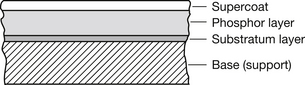
Figure 24.3 Section (not to scale) through a photostimulable plate. The function of the transparent supercoat is to protect the phosphor layer from mechanical damage, while the substratum layer binds the phosphor layer to the base, which provides a firm support to the plate.
This process is the basis of photostimulable plates which are used in computed radiography imaging systems (see Ch. 34).
In this chapter, you should have learnt the following:
• The meaning of the terms luminescence, fluorescence and phosphorescence (see Sect. 24.3).
• The mechanism of fluorescence (see Sect. 24.3.1).
• The meaning of the terms quantum detection efficiency, quantum conversion efficiency and scintillation efficiency (see Sect. 24.3.1).
• The mechanism of phosphorescence (see Sect. 24.3.2).
• The mechanism of thermoluminescence (see Sect. 24.3.3).
• Other uses of fluorescence in radiography (see Sect. 24.3.5).
• The mechanism of photostimulation radiography (see Sect. 24.4).
Further reading
Curry T.S.III, Dowdey J.E., Murry R.C.Jr. Christensen’s Physics of Diagnostic Radiography, fourth ed. London: Lee & Febiger, 1990. (Chapter 2)
Roberts D.P., Smith N.L., Gunn C. Radiographic Imaging: a Practical Approach. Edinburgh: Churchill Livingstone, 1994. (Chapters 2 and 5)
Webb S., editor. The Physics of Medical Imaging, second ed., Bristol: Institute of Physics, 2000. (Chapter 2)