Chapter 34 Production of the digital radiographic image
Chapter contents
34.1 Aim
The aim of this chapter is to introduce the reader to the principles of digital imaging as practised in the radiological department. The assumption is made that the reader has read and understood Chapter 25 which dealt with the basic mechanisms of image production. The consequences of producing a digital image will be discussed in Chapter 36.
34.2 The digital image
The old method of producing a radiograph using film and intensifying screens is an example of an analogue image. The information (or data) it contains is represented by a range of continuously varying densities or shades of grey. If such an image is scanned as a series of horizontal lines and the densities plotted on a graph, we would see an appearance similar to that shown in Figure 34.1A (see page 252).
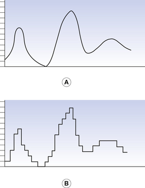
Figure 34.1 A horizontal line drawn across an image. (A) A conventional analogue image; (B) the same line as a digital image.
A digital image is divided into a series of small boxes called pixels, arranged in a series of rows and columns called a matrix (Fig. 34.2, see page 252). The density of each pixel has a numerical integer value. If we consider our initial radiograph, we could allocate the value 0 to the most dense value and 255 to the least dense value giving a digital scale of 256. Thus, any single pixel would have a discrete value between zero and 255 and our line would appear as a series of steps as shown in Figure. 34.1B. The smaller the image size and the larger the number of pixels in the image matrix, the better the spatial resolution of the image. If the pixels are too large, the individual pixels can be seen by the observer and distract from the image information.

Figure 34.2 An example of the matrix used for a digitized image. Each box of this matrix is a pixel.
Most modern digital imaging systems have a matrix of 1024×1024 pixels; the resultant image has 1 048 576 individual pixels. If such an image was displayed on a 20-cm square section of a monitor, each pixel will be a square of side just under 0.2 mm and so will be below the resolving power of the eye; thus we are aware of the overall image and do not see the individual pixels.
A digital image is any image in which the information is represented in discrete units, with integer values.
Digital imaging is used in all imaging modalities in the modern diagnostic imaging department. The process of converting the analogue radiation image from the patient into a digital image differs with each modality and application. However, the principle of changing this analogue signal into a digital one is common to all modalities and applications.
Digital imaging allows the construction of an image with a high spatial resolution, large dynamic range and good contrast resolution. In addition, the imaged data may also be processed by a computer to enhance the diagnostic value of the ‘raw’ unprocessed image. The data for these images, as already mentioned, can come from a variety of sources and will be received by some form of image receptor (imaging plate, digital array or transducer, for example). The signal then passes through several basic stages before a visible image is produced.
34.3 Digital image production
If the image is not already in the form of an electrical signal, the first stage of the conversion process is to convert the image to an electrical signal. (This may not be necessary with all imaging modalities.) The analogue electrical signal is converted into a digital one using a device known as an analogue-to-digital converter (ADC). Within the ADC, the signal undergoes three stages: scanning, quantization and coding.
34.3.1 Scanning
The incoming signal is scanned as a series of equally spaced horizontal lines. Each line is divided into a number of equally spaced points producing a series of small ‘boxes’; each ‘box’ forms a single picture cell element or pixel. To eliminate display errors, the scanning frequency must be at least twice the highest frequency present in the analogue image signal. This produces the image matrix (as already mentioned, the number of pixels per line), which is important as this controls the horizontal resolution of the image. A high rate of sampling produces a high-resolution image but is more demanding on the computing facilities. The effect of pixel size on resolution can be seen by viewing Figure 34.3 (see page 253). If viewed at close range, the individual pixels are quite noticeable. However, when viewed from a distance of about a metre, the eye cannot resolve the individual pixels.

34.3.2 Quantization
This process allocates a numerical integer to each pixel. On a scale of 1024, for example, each pixel can have an integer value between 0 and 1023. A typical TV camera video signal ranges from zero to 700 mV at peak white intensity. This scale permits the ADC to detect changes in the video signal as low as 0.7 mV.10−7 volts.
34.3.3 Coding
The final stage, coding, converts the numerical value produced by quantization into a binary number as this is the type of number ‘understood’ by the computer, which cannot understand conventional numbers. The data then pass from the ADC to the computer.
Where the signal is part of a ‘moving’ image such as produced during fluoroscopy, it is also important that the ADC can sample and process each individual frame of the image before it is replaced by the next frame in the sequence, and therefore it is desirable that the ADC has a high sampling rate.
34.4 Short-term storage, manipulation and display of digital images
The second stage of the conversion is carried out by the computer. The binary number passes to the central processing unit (CPU) of the computer which directs the data to an area of computer memory termed a frame store. When the data capture for the image is complete, it is recalled by the CPU and, if required, manipulated. This facility allows us, for instance, to alter the contrast and brightness of the image, to window on specific values within the image so that only structures of interest are displayed, to enhance the edges of structures or to subtract one image from another. These facilities are especially useful in studies using a contrast agent. Having manipulated the image as required, the binary values are recalled from the frame store and, if necessary, matched to the display capabilities of the VDU or monitor and passed to an output buffer (a storage area in the computer memory). Finally, once all data are modified and stored, the CPU monitors the transfer of the data to the appropriate output device. This process is shown diagrammatically in Figure 34.4 (see page 254).
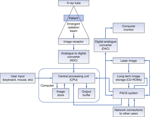
Figure 34.4 Block diagram of the major components of a digital imaging system. Note the picture archiving and communications system (PACS) component functions as an interface between the system and its long-term storage. It also permits communication between the internal departmental network and other hospital and external users.
The final stage is the conversion of the digital signals from the computer back into an analogue signal. This process is carried out by a device known as a digital-to-analogue converter (DAC) which operates in a reverse manner to the ADC. As each binary number is received by the DAC it is allocated a discrete absolute numerical value; this current then passes through an output resistor, resulting in an analogue voltage output.
This final stage is only necessary if the monitor is a cathode ray tube (CRT). If the monitor is a liquid crystal display (LCD) (which has a digital input), no conversion is necessary. The digital signal is also sent to a picture archiving and communications system (PACS). The PACS system has many functions: it provides long-term storage facilities for the digital image, and communicates with the departmental and hospital computer networks. This will be further discussed in Chapter 36 which considers the consequences of digital imaging. The digital signal may also be passed to a device such as a laser imager, where it is used to produce hard copy on a film, although this is very rare today.
34.5 Digital imaging in general radiography
Digital imaging systems in general radiography tend to be classed under two broad types, computed radiography (CR) or digital radiography (DR) – this latter system is sometimes referred to as direct digital radiography as it does not involve the need to take a digital plate to a plate reader.
34.5.1 Computed radiography
Computed radiography systems use photostimulable plates as a temporary store for the radiographic image (see Sect. 24.5). The plates are stored in CR cassettes. After the plate has been exposed to radiation, the operator places the cassette in a plate reader. Here the plate is removed from the cassette and scanned in a linear fashion using a laser beam. The information from the plate and patient information are matched and then sent through the computer system to appropriate workstations for viewing and reporting. Finally, the plate is ‘cleaned’ of any residual image information and inserted into the cassette where it is ready for use in the next imaging situation.
34.5.1.1 Construction and physics of the storage phosphor plates
A cross-section of a typical storage phosphor plate is shown in Figure 34.5 (see page 254). When the atoms in the phosphor layer (i.e. europium-activated barium fluorohalide (BaF(BrI):Eu2)) are stimulated by X-ray photons, then electrons in the valence band are moved to the higher energy of the electron traps in the ‘forbidden energy band’. This process has been described in detail in Chapter 24. The greater the number and energy of the X-ray photons interacting with the plate, the greater the number of electrons which have their energy raised and so enter the electron traps, and so an ‘X-ray image pattern’ is created on the plate. The plate is now read in the plate reader by scanning it with a laser beam. The electrons are given sufficient energy to be liberated and eventually drop back to the valence band. This drop in the electron energy causes the liberation of a light photon which is detected by a photomultiplier system and sent as an electrical signal to the computer system. The amount of light emitted and the strength of the electrical signal are proportional to the original intensity of X-rays which interacted with the plate. These samples of electrical signal are used to construct the digital image (see Sect. 24.5).
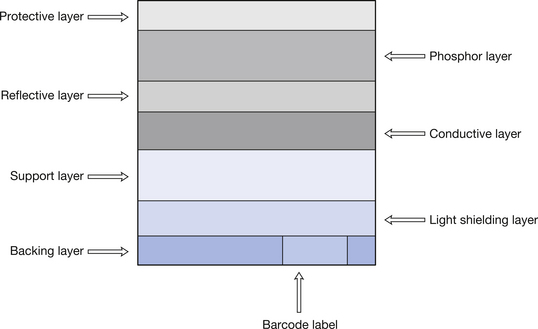
Figure 34.5 Cross-section through a typical CR imaging plate. The functions of the various layers are discussed in the text.
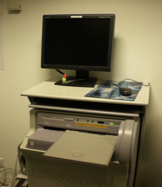
An example of a plate reader is shown in Figure 34.6.
34.5.2 Digital radiography
Digital radiography does not involve the operator taking an imaging plate to a plate reader. Instead the imaging device (flat-panel detector) is incorporated into the X-ray couch or erect stand and sends the image information to the computer as soon as the exposure is made. The image is then produced on the operator’s viewing monitor after a few seconds. Such a set-up is shown in Figure 34.7.
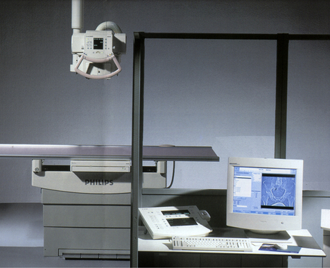
Figure 34.7 This is a typical direct digital technique setup showing the X-ray tube, the table, the operator’s console and the monitor with an image displayed on it.
(photograph courtesy of Philips Health care.)
The technology of flat-panel detectors can be divided into two major types – ‘direct conversion detectors’ and ‘indirect conversion detectors’.
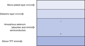
34.5.2.1 Direct conversion flat panel detectors
Figure 34.8 shows a section through a typical direct conversion flat-panel detector. The outer layer of the plate is a micro-plated electrode. This allows a charge to be applied via the dielectric layer to the amorphous selenium (a-Se) layer as shown in the diagram. The amorphous selenium layer absorbs X-ray photons and this results in the liberation of electrons. These electrons are directed by the charge pattern towards the silicon thin film transistors (TFTs). The TFTs act as switches which send the signal to the processing system where the software converts it to the appropriate greyscale for that pixel. The image is usually displayed on the display panel in the operator’s control area in less than 1 second after exposure.
34.5.2.2 Indirect conversion flat-panel detectors
Indirect conversion flat-panel detectors are similar to the direct conversion detectors except that the conversion is a two-step process. Figure 34.9 shows a section through a typical indirect conversion flat-panel detector. The crystals in the caesium iodide layer are struck by X-ray photons and emit light photons proportional to the energy and intensity of the X-ray photons. Caesium iodide crystals are needle shaped and so limit the spread of light emitted thus improving resolution. The light photons fall onto the amorphous silicon (a-Si) layer and cause the emission of electrons within this layer. These electrons are then directed towards the TFTs and the image is produced in a similar way to the direct conversion method. Because there is the potential for the light to diverge before being captured by the amorphous silicon layer, the resolution of this system may not be as high as the direct conversion system.
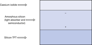
Figure 34.9 This is a diagrammatic representation of the construction of the material which will collect the image information from a single pixel in the matrix of an indirect imaging plate.
In this chapter, you should have learnt the following:
• What is meant by a ‘digital image’ in radiography (see Sect. 34.2).
• The main processes in digital image production (see Sect.34.3).
• The short-term storage, manipulation and display of digital images in radiography (see Sect 34.4).
• The basics of digital imaging as applied to general radiography (see Sect. 34.5).
Further reading
You may find Chapter 36 of this text, which discusses the implications of digital imaging, useful further reading.
Carter C.E., Veale B.L. Digital Radiography and PACS. Missouri: Mosby Elsevier, 2008.
Siegel E.L., Kolodner R.M. Filmless Radiology. New York: Springer, 1999.