Chapter 31 Monitoring and protection of X-ray tubes
Chapter contents
31.1 Aim
The aim of this chapter is to enable the reader to understand the concept of the rating of X-ray tubes and why it is monitored. The chapter will discuss factors which affect tube rating and the effects of single and multiple exposures on rating of the X-ray tube. An example of how a microprocessor is used to monitor these effects and prevent damage to the X-ray tube is illustrated.
31.2 Definition of rating
The general term rating is used to describe the practical limits that are inherent in any device. An example of this is that a fuse rated at 5 amperes will tolerate currents up to 5 amperes. If a current above 5 amperes passes through the fuse, then the fuse will melt, causing a break in the circuit. A high-tension transformer is a more complicated device than a fuse and so has a more complicated set of rating conditions (see Sect. 14.9). Similarly, the rating of an X-ray unit – the X-ray tube and the associated equipment – depends both on how it is constructed and how it is being used. The rating may be defined as follows:
The rating of an X-ray unit is the combination of exposure settings which the unit can withstand without incurring unacceptable damage.
All radiographic exposures cause slight wear and tear on the X-ray tube, the anode becomes more slightly pitted and the filament becomes slightly thinner as a result of any exposure. However, in this context, ‘unacceptable damage’ means damage that would seriously impair the performance of the unit for further exposures or might indeed make it inoperative. In this context, a single short exposure where the mA was above the rating of the tube might damage the anode by melting the focal track. Alternatively, a long exposure at low mA may again damage the anode if the total amount of heat generated in the anode caused a sufficient temperature rise to melt the tungsten. It is also true that multiple exposures, each of which is individually within the tube rating, might damage the tube because of the total heat accumulated in the anode by the exposure series. As the anode takes a finite time to cool after an exposure, the closer the exposures follow each other, the more likely the anode is to suffer thermal damage. For this reason, the rating for single and multiple exposures will be considered separately in this chapter.
31.3 Single exposures
The rating for a single exposure is affected by a number of different factors; some of these are under the control of the operator while others are not, as shown in Table 31.1 (see page 232).
Table 31.1 Factors affecting the rating of a particular X-ray tube
| SELECTABLE FACTORS | FIXED FACTORS |
|---|---|
| kVp mA | Rectification type |
| Rating of high-tension transformers | |
| Exposure duration | capacity of anode |
| Focal spot size | Diameter of anode |
| Operating mode – fluoroscopy or radiography | Speed of anode rotation |
| Anode angle | |
| Thermal capacity of tube shield | |
| Efficiency of heat loss from anode and tube shield |
In any particular unit, the non-selectable factors are fixed, so a rating must be used which is applicable to that set of circumstances, e.g. a rating appropriate to an X-ray tube connected to a two-pulse unit. The rating can be plotted as a graph showing the effect on the rating of varying the quantities in the selectable group. A simplified form of such a graph is shown in Figure 31.1. Here the rating curve corresponds to a 1.2-mm focus selection and a kVp selection of 80 kVp. The curve indicates the upper limit for all combinations of mA and time for this value of kVp. The points below the line are safe, whereas points above the line are unsafe because they would result in unacceptable damage to the X-ray tube. If we consider an exposure of 80 kVp, 100 mA and 0.2 seconds, then we can see that this exposure may be safely made, as the point P is below the 80-kVp line. Note that because of the wide range of exposure times possible, it is usual to use a logarithmic scale on the x-axis.
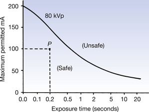
It can also be seen from the graph that higher values of mA will be tolerated for short exposure times – 150 mA at a time of 0.1 second is within the rating – whereas, at long exposure times, only lower values of mA are within the rating – for an exposure time of 2 seconds, the maximum mA permissible within the rating is 50 mA. In each case, the limiting factor is the anode temperature. For longer exposure times, there can be significant cooling of the anode during the exposure. This is shown by the flattening-off of the curve at longer exposure times.
In clinical practice, a range of kVp values is applied to the X-ray tube. Rating calculations take this and the focus size into account, producing separate rating graphs for broad and fine focus. Examples of such graphs are shown in Figure 31.2. Figure 31.2A in the chart is for the broad focus and part B is for the fine focus. As can be seen from these graphs, the rating of the tube is lower for the fine focus than for the broad focus. This is because for a fine focus, the electron beam is concentrated onto a smaller area, thus producing a higher temperature rise for the same value of mA.
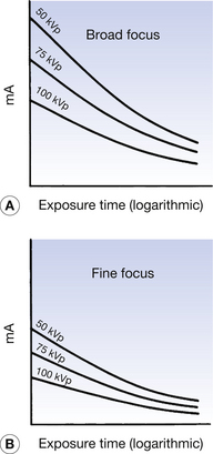
The figure also shows that larger values of mA are permitted as the kVp is reduced; the difference between the curves is most marked for the shorter exposure times. As was discussed in Chapter 30, electrons are produced at the filament of the X-ray tube and are accelerated towards the anode. The higher the kVp across the tube, the more kinetic energy each electron possesses when it interacts with the anode target. Thus, the same number of electrons per second (mA) will deliver more energy per second to the target and so will increase the possibility of thermal damage. The graph shows this inverse relationship between the kVp and the mA.
Consider a situation where for a given exposure time (t), the anode may be given a total energy E without causing thermal damage. The energy of a single electron crossing the X-ray tube is proportional to the kVp across the tube. The total number of electrons is related to the current (mA) and the exposure time (t).
Thus, for a given exposure time, halving the kVp should double the permissible mA.
Finally, the effect of different types of rectification when using the same X-ray tube needs to be considered. (see Figure 31.3) illustrates this effect for four different types of rectification, where the same focal spot and the same kVp have been selected. As can be seen from the graphs, the self-rectified circuit has the poorest rating, while the constant potential (or medium-frequency) circuit has the best rating. Also, note that the differences in rating are most marked at short exposure times. This is because the heating effect of individual pulses is most apparent in this situation. The more constant the heat production, the less the likelihood of thermal damage to the target – hence the best rating for constant potential.
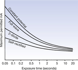
For longer exposure times, the thermal capacity (see Sect. 5.3.2) of the anode disc is the dominating factor. This is independent of the type of rectification and so the curves all tend to come closer together as the exposure time increases. Also, note that for longer exposure times the cooling of the tube shield and the heat dissipation within the high-tension transformer are significant factors in determining the rating of the tube and X-ray unit.
31.3.1 Rating of stationary anode and rotating anode X-ray tubes
In the stationary anode X-ray tube, the process of conduction loses heat from the target through the copper anode and thence to the oil surrounding the insert in tube shield. The process is limited by the melting point of copper (1083°C) and the rate at which conduction occurs. As a result, the rating of stationary anode X-ray tubes is much lower than that of rotating anode X-ray tubes. Such X-ray tubes have a very limited application. In the rotating anode X-ray tube, heat loss by conduction is discouraged by the design of the anode stem (see Sect. 30.5.2) and the main method of heat loss from the anode is by radiation. Efficient heat loss by radiation is achieved by designing the anode disc so that it can tolerate high temperature rises (remember that the rate of heat loss by radiation is proportional to the fourth power of the kelvin temperature). During large exposures, the anode disc often becomes incandescent and at such temperatures can lose heat effectively by radiation, hence the higher rating of the rotating anode tube.
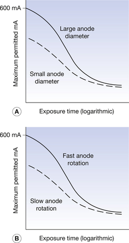
31.3.2 Effects of anode diameter and speed of rotation on tube rating
When we consider the rating of the rotating anode tube, we must consider not only the material used in its construction and its mass but also the effects of the anode diameter and the rate of anode rotation. In the rotating anode tube, the electrons land on the focal track around the bevelled circumference of the disc. This means that the heat is deposited around the whole disc instead of in the same area, as in the case of the stationary anode tube. Because this heat energy is now deposited over a larger area, there is a smaller temperature rise per unit area and rating is improved.
If we increase the anode diameter, we may increase its mass but this change also increases its circumference. This means that the heat energy is now deposited over a larger area and, as more atoms are involved in cooling, this leads to more efficient cooling, improving the rating. Doubling the diameter of the disc will increase its rating by 40–50%, but this has practical limitations because of the extra mechanical stress this imposes on the bearings. A simplified graph showing the improvement in rating is shown in Figure 31.4A (see page 234). If we double the speed of rotation of the anode, this means that only half the heat energy is deposited onto the anode for each rotation, although it makes twice as many rotations during a given exposure time. If there were no cooling between successive heating of the same point, there would be no advantage of increasing the rotational speed. The effect of increased anode rotation on the tube rating is shown in Figure 31.4B. Doubling the speed of rotation will again increase the rating by about 40–50%.
31.4 Multiple exposures
When single exposures are made, there is a comparatively long interval between exposures. If a series of exposures is made, there may be insufficient time for the anode disc to cool between exposures. While every single exposure in this series may be within the rating of the tube, the heating effect of subsequent exposures could raise the temperature of the anode above the permitted level, resulting in thermal damage to the focal track. In such cases, it is necessary to consider additional factors to be able to predict the safety of any combination of exposures.
31.4.1 Anode heating
The anode disc has a given mass and thermal capacity and so there is a given quantity of heat which will raise the whole anode disc to its maximum desirable operating temperature. This is known as the heat storage capacity of the anode and is expressed in kilojoules – in the example shown in Figure 31.5, this is 80 000 kilojoules.
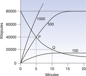
For long exposures such as during fluoroscopy, the cooling, which occurs during the exposure, becomes important in calculating tube ratings. The anode initially heats up fairly quickly but then tends towards a thermal equilibrium, which occurs when the rate of heat generated in the anode by the electron beam is exactly balanced by the rate of heat loss from the anode. Examples of anode heating curves for a particular tube are shown in Figure 31.5, where the number of kilojoules stored by the anode at any moment is plotted against time. The maximum heat storage capacity of this anode is 80 000 kilojoules. Three different exposure rates are shown:
1. The rate of 1000 kilojoules per second fairly rapidly exceeds the heat storage capacity of the anode and further exposure beyond this time would result in thermal damage.
2. The rate of 500 kilojoules per second establishes thermal equilibrium at the maximum heat storage capacity of the anode.
3. The exposure at 100 kilojoules per second – this would be the rate of heat production for a fluoroscopic kV of 100 kVp and a fluoroscopic current of 1 mA – produces thermal equilibrium with the anode at a fairly low temperature.
Note that in many cases it is convenient to show the heating and cooling curves on the same graphs.
31.4.2 Anode cooling
The heat stored in the anode is lost at a finite rate and a cooling curve showing the rate at which this heat is lost plotted against time (assuming that the anode has received its maximum permitted number of kilojoules at t=0) is shown in Figure 31.5. Suppose an exposure of 40 000 kilojoules is made: the point P shows this in the figure. The anode loses heat, as given by the curve below P, such that 5 minutes later, at point Q, only 20 000 kilojoules remains stored in the anode. An example of the use of such a graph is given below.
An exposure of 60 000 kilojoules is made on the X-ray tube for which Figure 31.5 is the cooling curve. The exposure requires to be repeated as soon as possible. How long must we wait between exposures to ensure that the anode does not exceed its maximum heat storage capacity?
Heat produced by the exposure=60 000 kilojoules.
The maximum heat storage capacity of the anode is 80 000 kilojoules and so it must cool down till it stores only 20 000 kilojoules before the exposure is repeated. By consulting the graph, it can be seen that this takes approximately 7 minutes.
In the cases discussed so far using cooling curves, it is assumed that no significant cooling of the anode takes place during the exposure. If this is not the case, e.g. during fluoroscopy, then anode heating curves are applied, as described above.
31.5 Automatic monitoring of rating
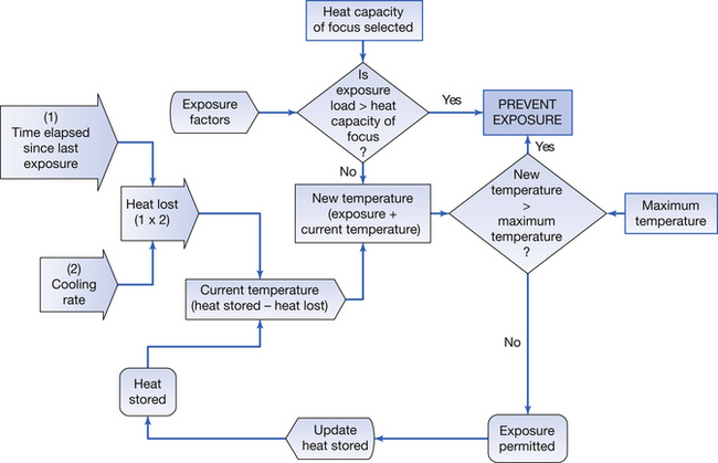
With older X-ray generators, it was necessary to use manufacturers’ rating charts to ensure that exposures, particularly multiple exposures, were within the rating for the generator. This was a complex, error-prone process. Modern units are fitted with devices such as thermistors (temperature-sensitive resistors) and photo diodes, which can be used to measure the temperature of the oil in the housing and of the anode disc. The electrical output from these is then passed to a microprocessor; this can then calculate whether the proposed exposure is within the rating of the tube. The microprocessor takes into account not only the heat generated by the exposure but also any heat already stored by the anode disc, and includes this in the calculation. This process is shown in flow chart form in Figure 31.6. Using stored data, the first stage checks that the individual exposure is within the permitted loading for the selected focus. The second stage checks that the exposure will not exceed the maximum rating for the X-ray tube. The heat lost between last exposure and current exposure is calculated and subtracted from the current temperature of the X-ray tube. The resultant figure is added to the heat generated by the exposure and this is then compared against the thermal capacity of the X-ray tube. If either of these tests results in an ‘overload’ condition, the computer activates an interlock, which will prevent the exposure until ‘safe’ conditions exist.
In this chapter, you should have learnt the following:
• The definition of rating when applied to the X-ray tube and its associated equipment (see Sect. 31.2).
• The factors affecting single exposures (see Sect. 31.3).
• A comparison of the rating of stationary anode and rotating anode X-ray tubes (see Sect. 31.3.1).
• The effects of the anode diameter and the speed of rotation on the rating of the rotating anode tube (see Sect. 31.3.2).
• Additional factors which affect rating for multiple exposures (see Sect. 31.4).
• Automatic monitoring of rating (see Sect. 31.5).