Chapter 30 The diagnostic X-ray tube
Chapter contents
30.1 Aim 221
30.2 Introduction 221
30.3 Construction of X-ray tubes 221
30.4 Construction of the tube shield (housing) 222
30.5 Construction of the rotating anode tube insert 224
30.6 Construction of the stationary anode tube insert 227
30.7 Principles of operation of the X-ray tube 227
30.8 Modern trends in X-ray tube design 229
Further reading 230
30.1 Aim
The aim of this chapter is to discuss the factors involved in the construction of diagnostic X-ray tubes.
30.2 Introduction
The rotating anode X-ray tube is the most common type of X-ray tube found in diagnostic imaging departments. The reason for this is that it is able to produce higher intensities of X-rays than the stationary anode tube. This is due to two factors:
1. The heat deposited in the anode during an X-ray exposure is spread over a larger area and so there is a smaller temperature rise at the anode surface.
2. The cooling characteristics of the rotating anode are superior to those of the stationary anode and this effective dissipation of heat means that larger loads can be applied without causing thermal damage to the target.
The stationary anode tube has a very low rating (see Ch. 31) and is only found in dental and some portable X-ray units. These units are connected to a 13-amperes mains supply. This limits the amount of electrical power that can be applied to it, preventing overloading of the tube.
30.3 Construction of X-ray tubes
The X-ray tube consists of two main components: the insert, which is mounted inside the tube shield.
These components and the light-beam diaphragm (we will discuss its role later in this chapter) are shown in Figure 30.1 (see page 222). The components of this tube are discussed individually in Section 30.5. Although the inserts for the rotating anode tube and the stationary anode tube differ substantially, the shields for both types of tube are very similar in design and function.
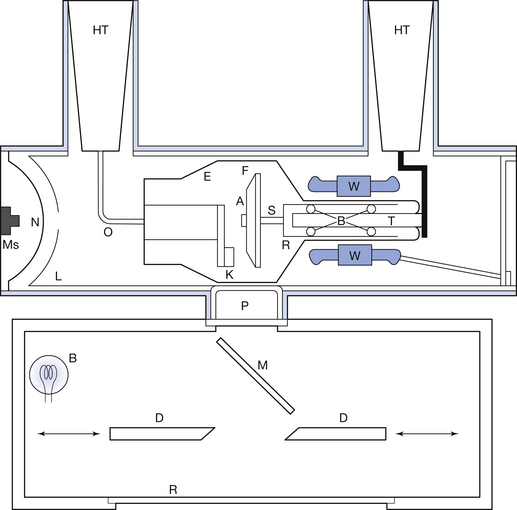
Figure 30.1 Simplified diagram of a rotating anode X-ray tube and diaphragm assembly. A, anode disc; B, light bulb; Br, bearings; D, moveable diaphragms (only one pair shown); E, glass envelope; F, focal track; HT, high-tension socket; K, cathode assembly; L, lead lining; M, mirror; Ms, microswitch; N, bellows; R, rotor assembly; S, anode stem; T, rotor support; O, oil; P, tube port and aluminium filter; R, plastic diaphragm front; W, stator windings.
30.4 Construction of the tube shield (housing)
It is necessary to protect the patient and the radiographer from the electrical and radiation hazards posed by the X-ray tube insert while in operation. The insert is incorporated within a suitable container – the shield – which must satisfy the following criteria:
• There must be no danger of electrical shock if the shield is touched during operation of the X-ray tube.
• No significant amounts of radiation should escape from the shield other than the radiation necessary for taking the radiograph.
• The shield must give secure support to the X-ray tube insert, the high-tension cables and the connecting cables within the shield.
• Adequate insulation must be provided between the insert and the tube shield to avoid electrical breakdown.
• There must be adequate cooling of the insert and facilities to allow expansion of the cooling oil.
• There must be facilities at the tube port to allow adequate filtration of the emergent beam so that low-energy radiations may be removed from the beam.
As can be seen from this list, the shield must satisfy many requirements. A schematic diagram of the shield for a rotating anode X-ray tube is shown in Figure 30.1. Note that the insert is held in position by a support at the anode end.
The metal casing surrounding the insert is made of either aluminium or steel and is lined with about 3 mm of lead to provide sufficient radiation protection. This housing is filled with pure oil that acts as an electrical insulator and as a coolant. A neoprene diaphragm at one end of the shield allows for expansion of the oil when the oil is heated. The assembly is usually fitted with a microswitch, which will prevent further exposures if the oil is very hot. Within the casing there is a radiolucent window – the tube port – which will allow the useful beam of radiation to leave the tube via the light-beam diaphragm.
30.4.1 Electrical safety
Electrical safety is designed around four basic principles:
1. Insulation of live components.
2. Earthling of component housings.
3. Restricted access to live components.
4. Isolation of the circuits from the mains supply when not in use.
All of the above are utilized in the design of the X-ray tube. Insulation exists between the live components and the housing in the form of the oil in the housing. The resistance of an insulator (and so its insulating properties) diminishes as the temperature of the insulator increases and so the role of the oil in heat dissipation is also important from the point of view of electrical safety.
The tube shield is connected to earth via the outer braiding of the high-tension cables (Fig. 30.2) and so the casing will always remain at earth potential. If a live wire within the casing becomes disconnected and touches the shield, then the current will readily flow to earth and the casing will present minimal electrical hazard to someone touching it at the time.
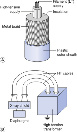
Figure 30.2 (A) Structure of a high-tension cable. Note the thickness of the insulation surrounding the central conductors. LT, low tension. (B) The X-ray tube shield is made electrically safe by connecting the copper braiding of the high-tension (HT) cables to both the shield and the casing of the high-tension transformer tank. The latter is securely earthed.
The live components in the X-ray tube are secured inside the tube shield and the ends and the high-tension cable connectors are securely fixed. This means that, under normal circumstances, the operator has no easy access to the live components. In addition, the circuits may be isolated from the mains by switches, fuses or circuit breakers.
30.4.2 Radiation safety
Radiation safety is important for the operators of X-ray equipment and for patients and others who may be in the vicinity at the time of making an X-ray exposure. The lead lining of the tube housing (Fig. 30.1) limits the radiation leakage from the tube and so provides protection to both the operator and the patient. It should be borne in mind that X-rays are emitted in all directions from the focus on the anode, but only those which pass through the tube port are allowed to leave the housing. The anode itself has a high absorption and so the lead lining at the anode end of the shield is often absent or thinner than at the cathode end.
The radiation leakage rate from the tube is normally measured at a distance of 1 metre from the housing and should not exceed an air kerma of 1.00 milligray per hour, measured at a distance of 1 metre from the focus (for definitions of the kerma and the gray, see Ch. 27). Any break in the lead lining will result in radiation leakage from the tube, so the leakage levels should be checked at regular intervals as part of the quality checks on the X-ray unit.
Radiation safety means exposing the patient only to the minimum dose necessary to produce a radiograph of acceptable quality. As we saw in Chapter 21, the spectrum of X-rays produced at the target is a continuous spectrum containing a mix of low-, medium- and high-energy photons. Some of the photons have very low energy and will not be able to pass through the patient to reach the image receptor. These photons would contribute to the patient dose but not to the image production. Some of these are removed by the glass envelope of the insert and the oil as the beam passes to the tube port. This is known as the inherent filtration of the tube. Further filtration takes place through the aluminium filters placed at the tube port (Fig. 30.1). These are known as added filtration. Thus, the total filtration of the beam is determined by the inherent filtration plus the added filtration. Details of this information are frequently marked on the end of the shield.
Scattered radiation contributes to the patient dose and the operator dose and causes degradation in the radiographic image quality. As we have seen in Chapter 23, the amount of scatter produced at a given set of exposure factors is dependent on the volume of tissue irradiated. The volume can be reduced by reducing the area irradiated using a light-beam diaphragm (Fig. 30.1). This also means that parts of the body not required on the radiograph can be protected from radiation. In this way, adequate collimation using a light-beam diaphragm (or cones) will reduce the patient dose and the operator dose and produce an improvement in the image quality.
30.5 Construction of the rotating anode tube insert
30.5.1 Insert envelope
X-ray production is at its most efficient when a vacuum exists between the cathode and the anode of the X-ray tube, so these structures are enclosed within an evacuated metal or heatproof glass envelope, which must be sufficiently strong to preserve this vacuum. Where glass envelope is used, it is joined to the anode spindle at one end and to the nickel cathode support at the other end by re-entrant seals – so called because the glass is shaped to point inwards at the area of contact. Slightly different glass seals are used at each end so that the thermal expansion of the glass is similar to that of the metal used in the construction of the anode spindle and cathode. This reduces the stress on the glass when the insert is hot and so limits the chance of cracking. The glass must be a good electrical insulator or a substantial current will flow through it when the high potential difference is applied between the anode and the cathode. However, electrical charges are built up on the inside of the glass during operation and so the glass must have sufficient electrical conductivity to allow these to leak away, usually between exposures, avoiding the build up of high amounts of static charge. The glass is gently rounded so that there are no sharp corners, which would allow the build up of high amounts of static charge (see Ch. 6).
During operation of the X-ray tube, a thin film of tungsten will be deposited on the inside of the envelope as a result of the release of tungsten vapour from the filament and the target. This film acts as a filter to emergent radiation, and where a glass envelope is used, may eventually cause electrical breakdown within the tube as it can act as an electrical conductor around the inside wall of the glass envelope. If this happens, the tube is classed as ‘gassy’ and is of no further use. The rate of tungsten vaporization can be reduced by not keeping the tube in the ‘prep’ mode (see Sect. 29.2) any longer than is required and by keeping exposures well within the rating of the tube (see Ch. 31).
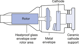
As shown in Figure 30.3, metal envelopes do not completely surround the insert. The cathode end of the envelope is formed from a ceramic material to provide the necessary electrical insulation between the anode and the cathode. The metal component of the envelope is earthed and, as a result, there is no build up of static charges on the metal envelope. This improves the focusing of the electron beam within the insert and reduces the effect of the build up of vaporized tungsten on the inner walls of the envelope.
30.5.2 The anode assembly
The simplest anode configuration is shown in Figure 30.1 where the anode consists of a disc with an accurately bevelled edge on which is deposited a target track. A number of different materials are used in the design of the anode disc, as shown in Table 30.1 (See page 225). A small amount of rhenium, which has an atomic number and melting point similar to that of tungsten, is alloyed with the tungsten of the target track. This improves the thermal expansion of the target track, making it more resistant to pitting. Tungsten is used as the main component in the target track for the following reasons:
• Tungsten has a high atomic number (Z=74) and so is an efficient producer of X-rays (see Ch. 21).
• Tungsten has a high melting point (3387°C), so it can withstand the heat generated during the X-ray exposure without melting.
• Tungsten has a low vapour pressure so it does not readily vaporize at its normal working temperature.
• Tungsten can be readily machined to give the smooth surface required for X-ray production.
The bevelled edge permits the use of the line focus principle. This results in an effective focus that is smaller than the real focus. The real focus can be longer than the effective focus. Thus, the filament may be relatively long without giving rise to excessive geometric unsharpness. Thermionic emission from the filament is proportional to its surface area and so a long filament will provide the high values of mA required by many exposures. The area over which the heat is deposited is the larger area of the real focus as shown in Figure 30.4. This is smaller than the apparent focus. The advantage of the line focus principle is that the temperature rise experienced by a large area for a given amount of heat is less than that experienced by a small area, since more atoms are able to take part in the heat dissipation processes. The line focus principle enables the anode to be designed so that the area of the real focus is about three times the area of the apparent focus. This enables a reasonable compromise between the need to minimize the temperature rise at the target (thus requiring a large focal area) and the need for minimizing the geometric unsharpness (thus requiring a small focal area). The anode face is usually set at an angle between 7° and 15° to the central axis of the X-ray beam. This is called the target angle.
Table 30.1 Materials used in the design of the modern rotating anode disc
| MATERIAL | USE | REASON FOR USE |
|---|---|---|
| Molybdenum | Disc | Half the density and twice the specific heat capacity of tungsten |
| Tungsten | Focal track (90%) | High atomic number. High melting point. Low vapour pressure. Suitable mechanical properties |
| Rhenium | Focal track (10%) | More elastic than tungsten, therefore less pitting of the focal track |
| Graphite | Disc backing | Low density. Acts as ‘heat sink’. Radiates heat by black-body radiation |
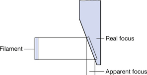
Figure 30.4 The line focus principle. Due to the angulation of the anode, apparent focus is much smaller than the real focus.
The disc has a central hole in it through which it is connected to a molybdenum anode stem and hence to the rotor of the induction motor (see Fig. 30.1). The rotor, stem and anode disc are accurately balanced so that no appreciable wobble occurs when the whole assembly rotates. The rotor is made to spin by the ‘rotating’ magnetic fields produced by the stator coils situated externally to the insert, using a similar process to the alternating current (AC) induction motor described in Chapter 12. The rotor moves smoothly on steel ball bearings coated in a soft metal, such as tin or silver, which acts as a lubricant but does not destroy the vacuum inside the envelope; a lubricant such as oil would evaporate and compromise the vacuum. The rotating magnetic field produced by the stator coils causes the rotor (and thus the anode disc) to rotate at the same frequency as the applied voltage.
The rotation of the anode during the exposure has the effect of elongating the area bombarded by the electron beam in a lateral direction, reducing the amount of heat generated per unit area even further. The positive terminal from the high-tension supply is connected to the rotor support, and through this there is a continuous electrical connection to the anode disc.
The conduction of heat from the anode disc to the ball bearings is inhibited by the fact that the anode stem has a small cross-sectional area (see Sect. 5.4.1) and is made of molybdenum (a relatively poor thermal conductor). However, some heat will inevitably reach the ball bearings and could cause sufficient expansion to produce a risk of seizure. This risk is reduced by applying a black coating to the outer surface of the rotor so that it loses heat efficiently by black-body radiation (see Sect. 5.4.4).
Many modem X-ray tubes also have graphite backing on the anode disc. This has a greater thermal capacity than molybdenum and draws heat from the anode and then dissipates it by black-body radiation. This results in the possibility of greater loads being applied to the anode and in reduced heat dissipation to the ball bearings.
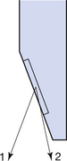
30.5.3 The anode heel effect
Consider Figure 30.5 (See page 226). X-rays are produced slightly below the surface of the target material. X-rays passing along path 1 will therefore pass through a smaller section of the target than those passing along path 2. There is absorption of the X-rays as they pass through the target and so the rays that pass through the greatest thickness of target are the more heavily absorbed – there will be a lower intensity of X-rays along path 2 than along path 1. This means that the X-ray intensity at the anode end of the beam will be less than at the central axis, while the intensity at the cathode end will be greater than at the central axis. This is known as the anode heel effect. The effect increases as the target angle is reduced and increases with the age of the X-ray tube. This latter increase is caused by the fact that the target becomes pitted with use.
30.5.4 The cathode assembly
The terms cathode and filament are often interchanged when discussing the X-ray tube. However, the correct usage of the term ‘cathode’ implies the whole cathode assembly, including the filament, focusing cup, supporting wires and cathode support. The filament is therefore part of the cathode but the cathode is not part of the filament.
The focusing cup, which supports the filaments, is offset from the central axis of the tube so that the electrons emitted from the filaments are aligned with the bevelled edge of the anode disc. It is made of either nickel or stainless steel, each of which has a high melting point and is a relatively poor thermionic emitter – each has a high thermionic work function. In addition, the thermal expansion of these materials is close to that of certain types of glass, thus reducing the stress on the seals during operation of the tube. When the filaments produce electrons by thermionic emission, these would repel each other by electrostatic repulsion –‘like’ charges repel – and so would strike a large area of focal spot. The area of the focal spot is reduced by the negative bias on the focusing cup which ‘squeezes’ the electrons together.
The filaments are made of a thin tungsten wire for the following reasons:
• Tungsten has a low thermionic work function and so will readily emit electrons by thermionic emission.
• Tungsten has a low vapour pressure and so does not easily evaporate. This helps prolong the life of the filament, as evaporation would cause the wire to become thin. It also prolongs the life of the tube as it prevents the formation of a tungsten film on the inner wall of the glass envelope.
• Tungsten is a strong metal that can be drawn into a thin wire that will not easily distort. This helps to maintain the shape of the filament helix over a period of time.
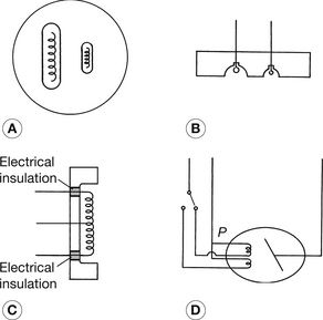
A rotating anode X-ray tube usually has two filaments. They may be positioned side by side, as shown in Figure 30.6. This is known as a dual-focus tube. Alternatively they may be positioned end to end, which means that the electron beams fall on different parts of the bevelled surface of the anode disc, which can be set at differing angles. This in-line configuration with different anode angles is referred to as a biangular tube. In both instances, the differing sizes of filament result in differing sizes of electron foci on the anode. The larger is known as the broad focus and would be used in situations where a high radiation output was required from the tube, while the smaller – the fine focus – would be used in situations where it is desirable to keep geometric unsharpness to a minimum. One side of each filament is connected to the focusing cup while the other is insulated from it (Fig. 30.6C). This connection between both filaments also forms the common connection between the filament circuit and the high-tension circuit. This is represented by point P in Figure 30.6D. From this diagram, it can be seen that three conductors are required in the high-tension cable coming to the cathode end of the X-ray tube. The secondary side of the filament transformer is also connected to one side of the high-tension circuit and this transformer could be a source of electrical hazard to the operator of the X-ray unit. For this reason and for reasons of ensuring good electrical insulation and heat dissipation, the filament transformer is contained in the same oil-filled tank as the high-tension transformer. All high-tension cables for X-ray units contain at least three conducting wires, even though only one is required at the anode end of the tube. This means that manufacturers only need to make (and X-ray departments only need to stock) one type of cable. Only one of the three wires at the anode end is used to make an electrical connection to the tube.
30.6 Construction of the stationary anode tube insert
30.6.1 The anode
The anode of the stationary anode tube, like the rotating anode, is constructed of two materials, copper and tungsten, and so is known as a compound anode. The main part of the anode assembly is made of copper because of its good thermal conductivity. The face of the anode is inclined at an angle of about 15° to the central axis of the insert and has an inset of a thin (about 2–3 mm) tungsten plate known as the target on which the electrons are focused.
30.7 Principles of operation of the X-ray tube
As we have seen in Chapter 21, X-rays are produced by electrons which are accelerated from the cathode to the anode of the X-ray tube. The number of electrons crossing the tube is controlled at the mA selector while the kinetic energy of the electrons – and thus the photon energy of the X-ray beam – is indicated by the kV selector.
30.7.1 Thermionic emission
The electrons are emitted by the heated filament by a process termed thermionic emission. In atoms, the outer shell electrons are more loosely bound than the inner electrons because they are further away from the nucleus (remember F ∝ 1/d2). The application of heat to a body increases the kinetic energy of its atoms and so increases the violence of their collisions. Because of these collisions, the outer electrons may be dislodged from the atom. Electrons so released near the centre of a body travel only a relatively short distance, but if they are released near the surface of the material, they may have sufficient kinetic energy to leave the body.
The higher the temperature of a body, the greater the kinetic energy of the atoms, and the greater number of electrons with sufficient energy to break free from the influence of the surface atoms of the body. We have also stated that the electrons, which are released by thermionic emission, are released from the surface atomic layers of the body. It follows that any alteration to these outer layers will alter the ability of a body to perform as a thermionic emitter. This has two practical consequences in radiography:
1. All the surfaces involved in thermionic emission (e.g. the tube filament) must be manufactured to a high degree of purity and must be kept scrupulously clean during assembly.
2. The thermionic emission characteristics of a body may be altered by the deliberate addition of ‘impurities’ either to the whole body or just to the body surface.
The efficiency of thermionic emitters may be compared by comparing their work function, which is normally expressed in electron volts (eV). The work function is the amount of work that must be performed by an electron in escaping from the body. Alternatively, it can be considered as the amount of work that must be performed on an electron to enable it to escape from the body. Substances which are good thermionic emitters have a lower work function than those that are poor thermionic emitters since, in the former, less work is required to allow the electrons to escape.
From the above discussion, it should be apparent that the amount of thermionic emission from a body is controlled by:
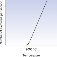
The relationship between the temperature of a tungsten filament and the number of electrons liberated in unit time is shown in Figure 30.7.
30.7.2 The space charge effect
If we assume that a body is electrically neutral before the application of heat, then each electron which leaves the body by thermionic emission will cause the body to have a net positive charge. After a very short time, a state of equilibrium is set up where electrons leave the body and enter a ‘cloud’ of electrons near its surface and are then attracted back to the body, i.e. electrons are attracted back to the body as fast as they are emitted. The number of electrons in this cloud remains fairly constant since electrons are entering and leaving the cloud at equal rates. This cloud of electrons is known as the space charge. If the temperature of the body is increased, then the number of electrons in the space charge will also increase due to the increased electron emission from the body. If the body is left to cool, it will reduce the space charge to zero by attracting electrons from it back to the body.
If we take a normal tungsten filament light bulb and switch it on, then the filament of this bulb is producing significant numbers of electrons by thermionic emission. These electrons form a space charge around the filament and return to it in the process described above. If we bring a large positive charge close to this light bulb, we can cause these electrons to ‘flash over’ to this positively charged body. If we switch off the power supply to the bulb, the filament cools down almost immediately, thermionic emission ceases and no further flash over occurs until the bulb is switched on again.
If a positively charged body is placed close to the space charge, then some of the electrons within the space charge will be attracted towards that body and so an electrical current flows between the heated body and the positive body via the space charge. This property is explored further in Section 30.7.3.
30.7.3 Tube current (mA) and filament current
Figure 30.8 shows a circuit diagram of the X-ray tube and high-tension circuit which has been greatly simplified to illustrate the difference between the tube current (mA) and the filament current (If). The relationship between the temperature of the tungsten filament and the number of electrons released by thermionic emission has already been discussed in Section 30.7.2. This section will look at the application of this information to the X-ray tube. In Figure 30.8, Bl represents the power supply across the X-ray tube and B2 represents the power supply across the filament. Suppose B2 causes a current If to flow through the filament circuit. The passage of this current through the filament causes the filament to heat and the subsequent temperature rise will cause electrons to be emitted by thermionic emission. These electrons are drawn towards the positive anode and constitute the tube current (mA). When all the electrons in the space charge are ‘in use’, it is said to be operating under saturation conditions. This is the normal operating condition of the X-ray tube. The only method of increasing the tube current is to increase the number of electrons in the space charge by increasing the temperature of the filament, causing more electrons to be released. Thus, the selection of a given mA by the radiographer determines the filament heating current required to produce that mA. A typical set of filament currents for an X-ray tube is shown in Table 30.2.
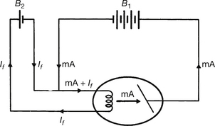
Figure 30.8 Simplified diagram to show the difference between tube current (mA) and filament heating current (If).
Table 30.2 Filament heating currents for different tube currents for a typical X-ray tube
| FILAMENT HEATING CURRENT (A) | TUBE CURRENT (mA) |
|---|---|
| 5 | 200 |
| 7.5 | 400 |
| 9 | 800 |
30.7.4 Electron focusing
During X-ray exposure, the anode of the X-ray tube is positively charged and the cathode is negatively charged. As a result of this, the electron space charge emitted from the filament is repelled from the negative cathode and attracted to the positive anode. The situation, which would arise if both the cathode and the anode were flat plates, is shown in Figure 30.9A (see page 229). The electric force field (see Ch. 6) consists of parallel lines starting at the anode and finishing at the cathode. Electrons are emitted from the filament, F, and are attracted to the positive anode. However, the electrons repel each other, so the beam of electrons will increase in size as it travels across the X-ray tube. The area, W, on the anode represents an unacceptably large focal area as this would produce a large geometric unsharpness on the resultant radiograph. This problem is overcome by the use of a focusing cup (see Sect. 30.5.4), as shown in Figure 30.9B. The thermionic electrons from F now experience two forces – one towards the anode and the other towards the central axis of the beam. The force towards the central axis of the beam is greater than the force of electrostatic repulsion between the electrons and so the beam of electrons is focused onto a small area of the anode – W in Figure 30.9B. The interactions between the electron beam and the anode are discussed in more detail in Chapter 21.
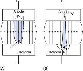
Figure 30.9 Simplified explanation of the focusing of electrons in the X-ray tube. (A) The result of no focusing cup on the cathode; (B) the electrostatic charge around the concave focusing cup directs the electrons from the thermionic emitter, F, towards the central axis so they strike a smaller area, W, on the anode.
30.7.5 Tube voltage (kVp)
The kVp selected by the radiographer controls the peak potential difference across the X-ray tube. The higher the kVp, the higher the peak potential difference and so the greater the force of attraction between the anode and the cathode. Because of this, the electrons will strike the anode with greater kinetic energies and so will produce more energetic X-ray photons. This was discussed in more detail in Chapter 21 when we considered X-ray production in detail. In this chapter, we will finish with a brief synopsis of the process so that the construction of various parts of the X-ray tube may be more clearly understood.
30.7.6 X-ray production
In the X-ray tube, electrons are produced at the cathode by thermionic emission. These electrons are then accelerated towards the anode and are made to give up their energy when they collide with the atoms of the target material. The main mechanism of X-ray production is when the electron is made to lose kinetic energy because of the pull of the positive nucleus of the target atoms. This is known as Bremsstrahlung radiation. The intensity (I) of the Bremsstrahlung radiation varies with both the energy (E) of the electrons striking the target and with the atomic number (Z) of the target material, as shown in the equations below:

or

The process of X-ray production is very inefficient and up to 99% of the energy of the electrons may be converted into heat, which must rapidly be transferred from the focal area to avoid damage to the target of the tube (see Sect. 5.7.2).
30.8 Modern trends in X-ray tube design
There are a number of modern trends in the design of specialist X-ray tubes that are not within the scope of this text. The reader should consult either more specialist texts on tube design or manufacturers’ literature. Specialist designs include:
• the metal/ceramic X-ray tube insert
• high-speed anode X-ray tubes
• stress-relieved anodes in rotating anode X-ray tubes
• X-ray tubes which allow automatic measurement of anode temperature
• alteration of the shape of the anode disc to allow improved loading (e.g. discus-shaped discs).
In this chapter, you should have learnt the following:
• The reasons why the stationary anode X-ray tube is of limited use in the modern X-ray tube and why it has been replaced by the rotating anode X-ray tube (see Sect. 30.2).
• The fact that X-ray tubes consist of two major components – the insert and the shield (see Sect. 30.3).
• The construction of the X-ray tube shield (see Sect. 30.3).
• The methods of ensuring the electrical safety of the X-ray tube shield (see Sect 30.4.1).
• The method of ensuring the radiation safety of the X-ray tube shield (see Sect 30.4.2).
• The construction of the rotating anode (see Sect 30.5).
• The construction of the anode assembly of the rotating anode X-ray tube (see Sect. 30.5.2).
• The reason for and the result of the anode heel effect (see Sect. 30.5.3).
• The construction of the cathode assembly of the rotating X-ray anode tube (see Sect. 30.5.4).
• The construction of the stationary anode X-ray tube (see Sect. 30.6).
• The construction of the cathode and filaments of the stationary X-ray tube (see Sect 30.6.1).
• The principles of operation of the X-ray tube (see Sect 30.7).
• The interrelationships between the X-ray tube current and the filament heating current (see Sect. 30.7.3).
• The requirement for and the method of achieving focusing of the electron beam across the X-ray tube (see Sect. 30.7.4).
• The effect of tube voltage on the emergent X-ray beam (see Sect. 30.7.5).
• A basic description of X-ray production (see Sect. 30.7.6).
Further reading
You will find further information on the rating of X-ray tubes in Chapter 31 of this text and more information on the factors affecting the X-ray spectrum in Chapter 21. In addition, you may find that sections from the following texts provide useful further reading.
Ball J.L., Moore A.D., Turner S. Ball and Moore’s Essential Physics for Radiographers, fourth ed. London: Blackwell Scientific, 2008. (Chapter 4)
Bushong S.C. Radiological Science for Technologists: physics, Biology and Protection, eighth ed. New York: Mosby, 2004. (Chapter 10)
Curry T.S.III, Downey J.E., Murry R.C.Jr. Christensen’s Physics of Diagnostic Radiography, fourth ed. London: Lee & Febiger, 1990. (Chapter 2)
Dowsett D.J., Kenny P.A., Johnston R.E. The Physics of Diagnostic Imaging. London: Chapman & Hall Medical, 1998. (Chapter 3)
Webb S., editor. The Physics of Medical Imaging, second ed, Bristol: Institute of Physics, 2000. (Chapter 2)