Panoramic Imaging
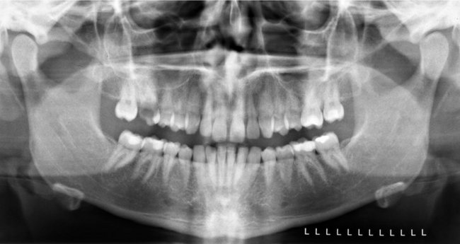
Panoramic imaging (also called pantomography) is a technique for producing a single tomographic image of the facial structures that includes both the maxillary and mandibular dental arches and their supporting structures (Fig. 11-1). This is a curvilinear variant of conventional tomography and is also based on the principle of the reciprocal movement of an x-ray source and an image receptor around a central point or plane, called the image layer, in which the object of interest is located. Objects in front of or behind this image layer are not clearly captured because of their movement relative to the centers of rotation of the receptor and x-ray source.
The principal advantages of panoramic images include the following:
• Broad coverage of the facial bones and teeth
• Convenience of the examination for the patient
• Use in patients unable to open their mouths
• Short time required to make a panoramic image, usually in the range of 3 to 4 minutes (This includes the time necessary for positioning the patient and the actual exposure cycle.)
• Patients readily understand panoramic films; thus they are also a useful visual aid in patient education and case presentation.
Panoramic images are most useful clinically for diagnostic problems requiring broad coverage of the jaws. Common examples include evaluation of trauma, location of third molars, extensive dental or osseous disease, known or suspected large lesions, tooth development (especially in the mixed dentition), retained teeth or root tips (in edentulous patients), temporomandibular joint (TMJ) pain, and developmental anomalies. These tasks do not require the high resolution and sharp detail available on intraoral images. Panoramic imaging is often used as the initial evaluation image that can provide the required insight or assist in determining the need for other projections. Panoramic images are also useful for patients who do not tolerate intraoral procedures well. However, when a full-mouth series of radiographs is available for a patient receiving general dental care, typically little or no additional useful information is gained from a simultaneous panoramic examination.
The main disadvantage of panoramic radiology is that the image does not display the fine anatomic detail available on intraoral periapical radiographs. Thus it is not as useful as periapical radiography for detecting small carious lesions, fine structure of the marginal periodontium, or periapical disease. The proximal surfaces of premolars also typically overlap. Accordingly, the availability of a panoramic radiograph for an adult patient often does not preclude the need for intraoral films for the diagnoses of most commonly encountered dental diseases. Other problems associated with panoramic radiography include unequal magnification and geometric distortion across the image. Occasionally the presence of overlapping structures, such as the cervical spine, can hide odontogenic lesions, particularly in the incisor regions. Further, clinically important objects may be situated outside the plane of focus (image layer) and may appear distorted or not present at all.
Principles of Panoramic Image Formation
Paatero and, working independently, Numata were the first to describe the principles of panoramic radiography. The following illustrations explain the operation of a panoramic machine. Two adjacent disks are rotating at the same speed in opposite directions as an x-ray beam passes through their centers of rotation (Fig. 11-2). Lead collimators in the shape of a slit, located at the x-ray source and at the image receptor, limit the central ray to a narrow vertical beam. Radiopaque objects A, B, C, and D stand upright on disk 1 and rotate past the slit. Their images are recorded on the receptor, which also moves past the slit at the same time. The objects are displayed sharply on the receptor because they are moving past the slit at the same rate and in the same direction as the receptor. This causes their moving shadows to appear stationary in relation to the moving receptor. Other objects between the letters and the center of rotation of disk 1 rotate with a slower velocity and are blurred on the receptor. Any objects between the x-ray source and the center of rotation of disk 1 move in the opposite direction of the receptor, and their shadows are also blurred on the receptor.
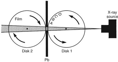
FIG. 11-2 Movement of the film and objects (A, B, C, and D) about two fixed centers of rotation. Pb, Lead collimator.
Figure 11-3 shows that the same relationship of moving film to image is achieved if disk 1 is held stationary and the x-ray source is rotated so that the central ray constantly passes through the center of rotation of disk 1 and, simultaneously, both disk 2 and the lead collimator (Pb) rotate around the center of disk 1. Note that, although disk 2 moves, the receptor on this disk also rotates past the slit. In this situation, as before, the objects A through D move through the x-ray beam in the same direction and at the same rate as the receptor. To obtain optimal image definition, it is crucial that the speed of the receptor passing the collimator slit (Pb) be maintained equal to the speed at which the x-ray beam sweeps through the objects of interest.
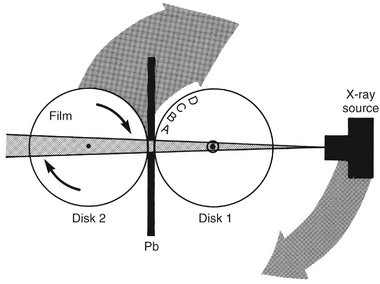
FIG. 11-3 Movement of the film and x-ray source about one fixed center of rotation. Pb, Lead collimator.
In the case where the receptor is a charge-coupled device (CCD) array, the image is electronically transmitted to the controlling computer as the x-ray beam hits it, and this transmission is continuous as the x-ray source and receptor are traveling around the patient. The resulting geometric projection characteristics are the same as if film or a photostimulable phosphor plate (PSP) had been used. This holds true for geometric distortions such as magnification and elongation, the presence of ghost images, superimposition of the cervical spine over midline structures, overlap of teeth, and left-right size variations from lack of proper positioning of the patient’s sagittal plane in the instrument.
Figure 11-4 shows that a patient may replace disk 1 and that objects A through D represent teeth and surrounding bone. In practice, the center of rotation is located off to the side, away from the objects being imaged. During the exposure cycle, the machine automatically shifts to one or more additional rotation centers. The rate of movement of the receptor behind the slit is regulated to be the same as that of the central ray sweeping through the dental structures on the side of the patient nearest the receptor. Structures on the opposite side of the patient (near the x-ray tube) are distorted and appear out of focus because the x-ray beam sweeps through them in the direction opposite that in which the image receptor is moving. In addition, structures near the x-ray source are so magnified (and their borders so blurred) that they are not seen as discrete images on the resultant image. These structures appear only as diffuse phantom or ghost images. Because of both these circumstances, only structures near the receptor are usefully captured on the resultant image. Structures located more centrally in the body relative to the jaws, such as the hyoid bone and epiglottis, appear on the right, left, and sometimes central areas of the final image.
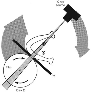
FIG. 11-4 Movement of the film and x-ray source about a shifting center of rotation. Pb, Lead collimator.
Most panoramic machines now use a continuously moving center of rotation rather than multiple fixed locations. Figure 11-5 shows a continually moving center of rotation. This feature optimizes the shape of the image layer to reveal the teeth and supporting bone. This center of rotation is initially near the lingual surface of the right body of the mandible when the left TMJ is imaged. The rotation center moves forward along an arc that ends just lingual to the symphysis of the mandible when the midline is imaged. The arc is reversed as the opposite side of the face is imaged. In some contemporary panoramic machines, the shape of the image layer can be adjusted to better conform to the shape of the patients’ mandibulofacial anatomy or to better show specific anatomic areas such as the TMJ or the maxillary sinuses. This is accomplished through varying the shape of the moving center of rotation, and allows better representation of children, unusually configured patients, and specific anatomic sites of interest.
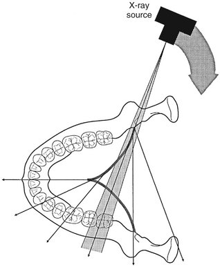
FIG. 11-5 Movement of the x-ray source and beam. The dark line shows a continuously moving center of rotation. As the source moves behind the patient’s neck and the anterior teeth are imaged, the center of rotation moves forward along the arc (dark line) toward the sagittal plane. The x-ray source continues to move around the patient to image the opposite side.
IMAGE LAYER
The image layer is a three-dimensional curved zone, or “focal trough,” where the structures lying within this layer are reasonably well defined on final panoramic image. The structures seen on a panoramic image are primarily those located within the image layer. Objects outside the image layer are blurred, magnified, or reduced in size and are sometimes distorted to the extent of not being recognizable. The shape of the image layer varies with the brand of equipment used. Figure 11-6 shows the general shape of the image layer used in panoramic machines. The factors that affect its size are variables that influence image definition: arc path, velocity of the receptor and x-ray tube head, alignment of the x-ray beam, and collimator width. The location of the image layer can change with extensive machine use, so recalibration may be necessary if consistently suboptimal images are produced.
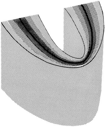
FIG. 11-6 Focal trough. The closer to the center of the trough (dark zone) an anatomic structure is positioned, the more clearly it is imaged on the resulting radiograph.
As the position of an object is moved within the image layer, the size and shape of the resultant image change. Figure 11-7, A through F, illustrates the influence of patient positioning on image size and shape. Figure 11-7, A and B, shows a mandible supporting a brass ring properly aligned in the middle of the image layer. Note the even magnification of the ring and the images of the anterior teeth in proper proportion. Figure 11-7, C and D, shows the same mandible positioned 5 mm anterior to the middle of the center of the image layer. This position causes distortion of the ring in the horizontal dimension, with the ring appearing thinner and a commensurate decreased width of the images of the teeth. Figure 11-7, E and F, shows the same mandible positioned 5 mm posterior to the middle of the focal trough. Now the horizontal distortion results in the ring appearing wider and a commensurate increased width of the projected teeth. On these images the vertical dimension, in contrast to the horizontal dimension, is little altered, although it appears to be. These distortions result from the reciprocal horizontal movements of the receptor and x-ray source. Thus, as a general rule, when the structure of interest, in this case the mandible, is displaced to the lingual side of its optimal position in the image layer, toward the x-ray source, the beam passes more slowly through it than the speed at which the receptor moves. Consequently, the images of the structures in this region are elongated horizontally on the image and they appear wider. Alternatively, when the mandible is displaced toward the buccal aspect of the image layer, the beam passes at a rate faster than normal through the structures. In the example shown, because the receptor is moving at the proper rate, the representations of the anterior teeth are compressed horizontally on the image, and they appear thinner. Special attention must be paid to these considerations in following the progress of a bony lesion, especially in the anterior region. As a result of improper patient positioning the lesion may appear greater (enlarging) (see Figure 11-7, F) or reduced (healing) (see Figure 11-7, D) on successive images. Thus the importance of careful alignment and positioning of the patient’s dental arches within the area of the image layer is apparent.
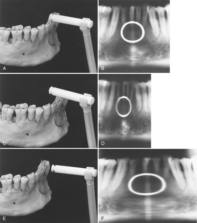
FIG. 11-7 A, Mandible supporting a metal ring positioned at the center of the focal trough. The incisal edges of the mandibular teeth are indexed by a bite rod–positioning device. The mandible is positioned at the center of the trough. B, Resultant panoramic radiograph. C, Mandible and ring positioned 5 mm anterior to the focal trough. The incisal edges of the teeth are anterior to the trough. D, Resultant panoramic radiograph demonstrating the horizontal minification of both ring and mandibular teeth. E, Mandible and ring positioned 5 mm posterior to the focal trough. The incisal edges of the teeth are also posterior to the trough. F, Resultant panoramic radiograph demonstrating the horizontal magnification of both ring and mandibular teeth.
The same principle applies to the patient’s sagittal plane being rotated in the image layer. The posterior structures on the side to which the patient’s head is rotated will be magnified in the horizontal dimension because the posterior structures will be moved away from the image receptor, whereas posterior structures on the opposite side will be moved closer to the image receptor and will be reduced in horizontal dimension. The resulting image will have horizontally large molar teeth and mandibular ramus, and severe premolar overlap, on one side and horizontally smaller molar teeth and mandibular ramus on the other side. This must not be confused with a congenital or developmental facial asymmetry (This positioning artifact is demonstrated in Figure 11-8).
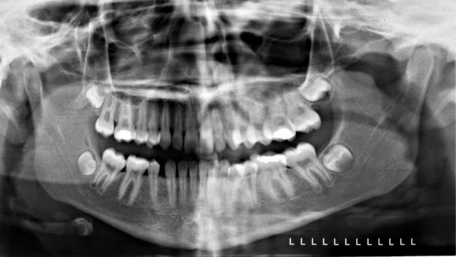
FIG. 11-8 Panoramic image showing positioning error-rotation of the sagittal plane. The patient’s head was rotated to the left, moving the right side closer to the receptor and the left side further from the receptor. Note the relative magnification of the left-sided molar teeth, mandibular ramus, and condyle and the severe overlap of the posterior teeth. It is important to recognize this fairly common distortion and not to mistake it for a skeletal asymmetry.
PANORAMIC MACHINES
A number of companies manufacture high-quality film-based and digital panoramic machines. The Othoralix 8500 (KaVo Dental Corp., Gendex Dental Systems, Lake Zurich, Ill. [Fig. 11-9]), the Proline XC (Planmeca Oy, Helsinki, Finland [Fig. 11-10]), and the Orthophos XG-Plus (Sirona Dental Systems GmbH, Bensheim, Germany [Fig. 11-11]) are all highly versatile. In addition to producing standard panoramic images of the jaws, they have the capability of adjusting to patients of various sizes and making frontal and lateral images of TMJs. These machines also are capable of producing tomographic views through the sinuses and cross-sectional views of the maxilla and mandible. These views are acquired by having special tube head and film movements programmed into the machine. Each machine also has the capability for adding on a cephalometric attachment to allow exposure of standardized skull views. Some machines further have the capability of automated exposure control. This is accomplished by measuring the amount of radiation passing through the patient’s mandible during the initial part of the exposure and adjusting the imaging factors (peak kilovoltage [kVp], milliamperage [mA], and speed of imaging movements) to obtain a correctly exposed image. Finally, all of these machines are available in CCD-digital configurations.
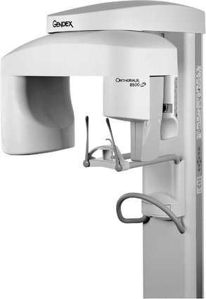
FIG. 11-9 Orthoralix 8500 panoramic machine. (Courtesy Orthoralix 8500, KaVo Dental Corp., Gendex Dental Systems, Lake Zurich, Ill.)
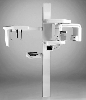
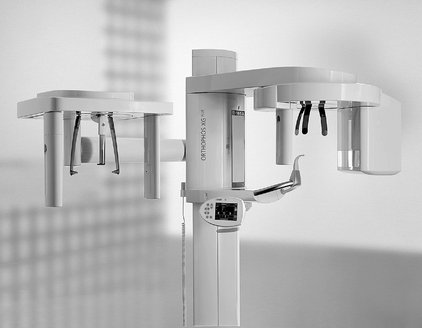
FIG. 11-11 Orthophos XG-PLUS panoramic machine. (Courtesy Sirona Dental Systems GmbH, Bensheim, Germany.)
There are now computer-controlled multimodality machines in which the direction and speed of movement of the tube head and film are highly variable, in some cases including multidirectional tomography. This allows the machines to be programmed to make tomographic views through many areas of the head. For instance, they can be programmed to image frontal or lateral views of the TMJs, coronal or sagittal sections through the maxillary sinuses, and cross-sectional cuts through a predetermined portion of the maxilla or mandible. These machines have much greater versatility than the conventional panoramic machines, and they are more expensive. Most of the special examinations made on these machines use circular or hypocycloidal tomography (see Chapter 13). The use of such instruments has substantially diminished in recent years with the steadily increasing use of cone-beam computed tomography (CBCT, see Chapter 14). Several new panoramic machines are also capable of accomplishing some degree of CBCT imaging.
Patient Positioning and Head Alignment
To obtain diagnostically useful panoramic radiographs, it is necessary to properly prepare patients and to position their heads carefully in the image layer. Dental appliances, earrings, necklaces, hairpins, and any other metallic objects in the head and neck region should be removed. It may also be wise to demonstrate the machine to the patient by cycling it while explaining the need to remain still during the procedure. This is particularly true for children, who may be anxious. Children should be instructed to look forward and to not follow the tube head with their eyes.
The anteroposterior position radiograph of the patient is achieved typically by having patients place the incisal edges of their maxillary and mandibular incisors into a notched positioning device (the bite-block). Patients should not shift the mandible to either side when making this protrusive movement. The midsagittal plane must be centered within the image layer of the particular x-ray unit.
Placement of the patient either too far anterior or posterior results in significant dimensional aberrations in the images. Too far posterior results in magnified mesiodistal dimensions through the anterior sextants and resulting “fat” teeth (see Figure 11-7, F). Too far anterior results in reduced mesiodistal dimensions through the anterior sextants and resulting “thin” teeth (see Figure 11-7, D). Failure to position the midsagittal plane in the rotational midline of the machine results in a radiograph showing right and left sides that are unequally magnified in the horizontal dimension (see Fig. 11-8). Poor midline positioning is a common error, causing horizontal distortion in the posterior regions, excessive tooth overlap in the premolar regions and, on occasion, nondiagnostic, clinically unacceptable images. A simple method for evaluating the degree of horizontal distortion of the image is to compare the apparent width of the mandibular first molars bilaterally. The smaller side is too close to the receptor and the larger side is too close to the x-ray source.
The patient’s chin and occlusal plane must be properly positioned to avoid distortion. The occlusal plane is aligned so that it is lower anteriorly, angled 20 to 30 degrees below the horizontal. A general guide for chin positioning is to place the patient so that a line from the tragus of the ear to the outer canthus of the eye is parallel with the floor. If the chin is tipped too high, the occlusal plane on the radiograph appears flat or inverted, and the image of the mandible is distorted (Fig. 11-12, A). In addition, a radiopaque shadow of the hard palate is superimposed on the roots of the maxillary teeth. If the chin is tipped too low, the teeth become severely overlapped, the symphyseal region of the mandible may be cut off the film, and both mandibular condyles may be projected off the superior edge of the film (Fig. 11-12, B). Patients are positioned with their backs and spines as erect as possible and their necks extended. Having patients place their feet on a foot support and using a cushion for back support may facilitate proper back positioning in seated units. These devices help straighten the spine, minimizing the artifact produced by a shadow of the spine.
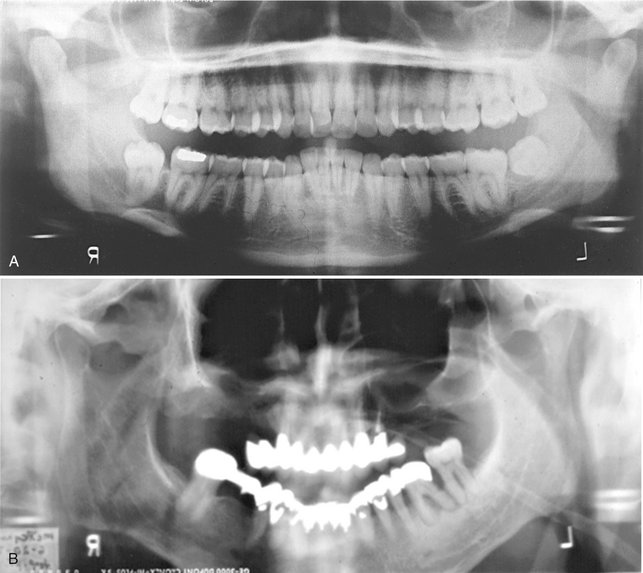
FIG. 11-12 Panoramic radiographs demonstrating poor patient head alignment. A, The chin and occlusal plane are rotated upward, resulting in overlapping images of the teeth and an opaque shadow (the hard palate) obscuring the roots of the maxillary teeth. B, The chin and occlusal plane are rotated downward, cutting off the symphyseal region on the radiograph and distorting the anterior teeth.
Proper neck extension is best accomplished by using a gentle upward force on the mastoid eminences when positioning the head in a manner similar to applying cervical traction. Allowing patients to slump their heads and necks forward causes a large opaque artifact in the midline created by the superimposition of an increased mass of cervical spine. This shadow obscures the entire symphyseal region of the mandible and may require that the radiograph be retaken (Fig. 11-13). Finally, after patients are positioned in the machine, they should be instructed to swallow and hold the tongue on the roof of the mouth. This raises the dorsum of the tongue to the hard palate, eliminating the air space and providing optimal visualization of the apices of the maxillary teeth.
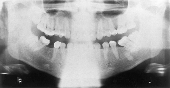
Image Receptors
Intensifying screens (see Chapter 5) are routinely used in panoramic radiography because they significantly reduce the amount of radiation required for properly exposing a radiograph. Fast films combined with high-speed (rare earth) screens are indicated for most examinations. In most cases, the manufacturer provides panoramic machines with intensifying screens. The type of screen (manufacturer and model) is printed in black letters on each screen and clearly projected onto the radiograph. With rare earth screens and fast films, the patient’s skin exposure from panoramic radiography is approximately equivalent to four bitewing views made with F-speed film.
Most manufacturers have developed direct digital acquisition panoramic machines. The receptor on such a machine is either an array of CCDs or a film-sized PSP plate rather than film. The CCD array transmits an electronic signal to the controlling computer, which displays the image on the viewscreen as it is being acquired. The software of the unit makes internal adjustments to the acquired data to render an interpretable image on the screen. The PSP plate is processed in the same manner as an intraoral PSP, and a similar image characteristic adjustment is automatically performed by the software package. Both these digital modalities allow the user to perform postprocessing modifications on the image, including linear contrast and density adjustments, black/white reversal, area of interest magnification, edge enhancement, and color rendering. Most units acquire and store their electronic data in DICOM format (Digital Imaging and COmmunication in Medicine); this allows for rapid telecommunication of images worldwide to all DICOM compliant workstations. DICOM is the international standard language for the electronic communication of digital images, be they radiographs, photographs, histopathologic slides, or any other type of “picture image.” The American Dental Association recommended that all digital x-ray units manufactured after 2004 be DICOM compliant. These units are becoming more widely used as dentistry increases its use of direct digital imaging and electronic patient records.
All panoramic images should have some mechanism for automatically marking the patient’s left or right sides on the image. Also, the patient’s name, age, and the date the image was acquired should be indicated, with markers, photographic imprinting, or glued labels. The dentist’s name must be on the image. No significant anatomic structures should be obscured by any of these labels or markings. Also, no parts of the image are trimmed to make the film fit the patient’s chart.
Panoramic Film Darkroom Techniques
Special darkroom procedures are needed when panoramic film is being processed. These films are far more light sensitive than intraoral films, especially after they have been exposed. A reduction in darkroom lighting from that used for conventional intraoral film is necessary. A Kodak GBX-2 filter can be installed with a 15-watt bulb at least 4 feet from the working surface. An ML-2 filter should not be used because it fogs panoramic film. Panoramic film should be developed either manually or in automatic film processors according to the manufacturer’s recommendations. Obtaining optimal results relies on the same care to develop, rinse, fix, and wash panoramic films as is taken with intraoral films.
Interpreting the Panoramic Image
As with all image interpretation, the starting points are the systematic analysis of the image and a thorough understanding of the appearances of the normal anatomic structures and their variants on the image. Panoramic images are quite different from intraoral images and demand a disciplined and focused approach to their interpretation. Recognizing normal anatomic structures on panoramic radiographs is challenging because of the complex anatomy of the midface, the superimposition of various anatomic structures, and the changing projection orientation. The many potential artifacts associated with machine and patient movement, patient positioning, and unusual patient anatomy must be identified and understood. The absence of a normal anatomic structure may be the most important finding on the image. Thus it is essential to identify the presence and integrity of all the major anatomic structures.
Most images in dentistry are two-dimensional representations of three-dimensional structures. Thus, on a posteroanterior (PA) skull film, orbital rims, nasal conchae, teeth, cervical vertebrae, and petrous ridges are all in sharp focus on the image, although they may be as much as a foot apart from each other. Although this presents less of an interpretation problem with panoramic images, which are curved image “slices” of the mandibulofacial tissues, there is still a thickness to the tomogram which must be considered, and the clinician must relate the structures on the image to their relative positions in the midfacial skeleton. An example of this three-dimensionality is the relative positioning of the external oblique and mylohyoid ridges in the mandible: on the panoramic image, they generally both appear sharp, whereas physically the external oblique ridge is on the mandibular buccal surface and the mylohyoid ridge is on the mandibular lingual surface, separated by several millimeters. When panoramic images are viewed, it is important for the clinician to remember this principle and to attempt to visualize the structures three-dimensionally in his or her mind.
It is helpful to view the image as if looking at the patient, with the structures on the patient’s right side positioned on the viewer’s left (Fig. 11-14). Thus the image is presented in the same orientation as that of periapical and bitewing images, making the interpretation more comfortable. It is extremely important to recognize the planes of the patient that are represented in different parts of the panoramic image. The panoramic image is actually three images in one: left and right lateral images posterior to the canines and a PA image anterior to the canines. The anterior sextants are also subject to the most dimensional distortion and to superimposition artifacts from the cervical vertebrae. Thus a useful mental approach to the panoramic image is to consider it as two lateral views surrounding a PA view in the middle, a sort of Mercator projection of the mid and lower face. This mental approach to viewing the panoramic image is illustrated by the panoramic and lateral and PA cephalometric images in Figure 11-15 and by the opened skull in Figure 11-16.
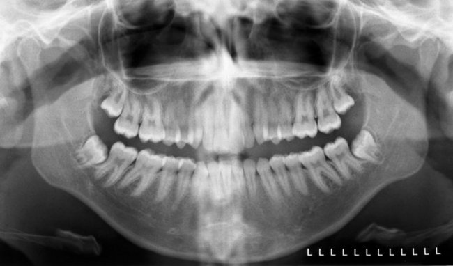
FIG. 11-14 Properly acquired and displayed panoramic image of an adult patient. Note that the patient’s left side is indicated on the image and that the image is oriented as if the clinician were facing the patient. This is the same orientation used with a full mouth series, making it easier for the clinician to orient himself or herself and to interpret the image.
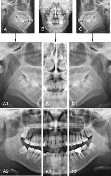
FIG. 11-15 Intellectual Segmentation of the Panoramic Image.
The panoramic image is composed of right and left lateral images connected in the middle by a PA image; it looks similar to a Mercator projection of the globe. This is appreciated by comparing the segmented panoramic image and the labeled structures to the matching cephalometric films acquired on the same patient. A-C, Left lateral, PA, and right lateral cephalometric images. These images are cropped and aligned to produce A1-C1. A2-C2 show a segmented panoramic image on the same patient. Note the similarities between the lateral cephalometric images and the panoramic image posterior to the canines, and between the PA cephalometric image and the panoramic image between the canines. Thus, when interpreting a panoramic image, the clinician should think of viewing left and right lateral projections of the midface, connected in the middle by a PA projection.
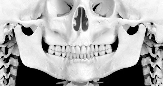
FIG. 11-16 This figure shows the bones of the mandible, midface, cervical spine and skull base as they appear on a panoramic image. Most important, this appearance is composed of left and right lateral views of the skeleton posterior to the canines, and an anterior view anterior to the premolars.
As with all image viewing, you should mask out extraneous light from around the image, dim the room lights, and when possible, work seated in a quiet room. This applies equally to viewing digital images on a computer display and traditional film radiographs on a viewbox.
THE MANDIBLE
Studying the mandible (Figs. 11-17 and 11-18) can be compartmentalized into the major anatomic areas of this curved bone:
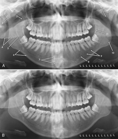
FIG. 11-17 Mandibular Bony Anatomic Structures on the Panoramic Image.
The labeled (A) and unlabeled (B) images are duplicate images of the same patient. 1, Mandibular condyle. 2, Neck of mandibular condyle. 3, Coronoid process of mandible. 4, Ghost image, posterior aspect of inferior border of left side of mandible. 5, Inferior alveolar (mandibular) canal. 6, Inferior border of mandible. 7, Superimposed shadow of cervical vertebrae. 8, Mental foramen. 9, Submandibular fossa (lingual salivary gland depression) (also see Fig. 11-19). 10, Mandibular angle. 11, External oblique ridge. 12, Sigmoid notch.
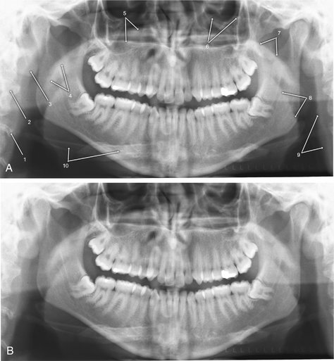
FIG. 11-18 Spinal, Neck, and Soft Tissue Anatomic Structures on the Panoramic Image.
The labeled (A) and unlabeled (B) images are duplicate images of the same patient. 1, Schmörl’s node (variant of normal anatomy of the vertebral body). 2, Cervical vertebra. 3, Ear lobe. 4, Soft palate and uvula. 5, Hard palate (the lower line is the junction of the hard palate and the lateral wall of the nasal cavity on the tube side, and the upper line is the junction of the hard palate and lateral wall of the nasal cavity on the receptor side). 6, Orbital rim. 7, Floor of nasopharynx (upper surface of soft palate). 8, Posterior surface of tongue. 9, Posterior pharyngeal wall. 10, Hyoid bone.
The clinician should be able to follow a cortical border around the entire bone, with the exception of the dentate areas. This border should be smooth, without interruptions (“step deformities”) and should have symmetric thicknesses in comparable anatomic areas (e.g., angles, inferior borders of bodies, posterior borders of rami). The trabeculation of the mandible tends to be more plentiful in the anterior regions, whereas the marrow compartment increases toward the angle and into the ramus; however, these trabecular patterns and densities should be relatively symmetric. This is especially true in children, who have very sparse trabeculation throughout the deciduous and mixed dentition stages.
The mandibular condyle is generally positioned slightly anteroinferior to its normal closed position because the patient has to slightly open and protrude the mandible to engage the positioning device in most panoramic machines. The TMJ can be assessed for gross anatomic changes of the condylar head and glenoid fossa; the soft tissues, such as the articular disc and posterior ligamentous attachment, cannot be evaluated. The glenoid fossa is part of the temporal bone, and as such it can be pneumatized by the mastoid air cells. This can result in the appearance of a multilocular radiolucency in the articular eminence and the roof of the glenoid fossa, a variant of normal. More definitive osseous assessment of the TMJ is accomplished by using complex motion tomography, CBCT, or computed tomography (CT), and magnetic resonance imaging (MRI) is the examination of choice for evaluation of the disc and pericondylar soft tissues (Brooks, 1997).
Shadows of other structures that can be superimposed over the mandibular ramal area include the following:
• Pharyngeal airway shadow, especially when the patient is unable to expel the air and place the tongue in the palate during the exposure
• Posterior wall of the nasopharynx
• Cervical vertebrae, especially in patients with pronounced anterior lordosis, typically seen in severely osteoporotic individuals
• Ear lobe and ear decorations
• Nasal cartilage and nasal decorations
• Dorsum of the tongue and tongue decorations
• Ghost shadows of the opposite side of the mandible and metallic decorations
From the angle of the mandible, viewing should be continued anteriorly toward the symphyseal region. A fracture often manifests as a discontinuity (step deformity) in the inferior border; a sharp change in the level of the occlusal plane indicates that the fracture passes through the tooth-bearing area, whereas a cant in the entire occlusal table without a step deformity in the occlusal plane indicates that the fracture is posterior to the tooth-bearing area. The width of the cortical bone at the inferior border of the mandible should be at least 3 mm in adults and of uniform density. The bone may be thinned locally by an expansile lesion such as a cyst or thinned generally by systemic diseases such as hyperparathyroidism and osteoporosis. The outlines of both sides of the mandible should be compared for symmetry, noting any changes. Asymmetry of size may result from improper patient positioning or conditions such as hemifacial hyperplasia or hypoplasia. The hyoid bone may be projected below or onto the inferior border of the mandible.
Trabeculation is most evident within the alveolar process. The mandibular canals and mental foramina are usually clearly visualized in the ramus and body regions of the body of the mandible. Typically the canals exhibit uniform width or gentle tapering from the mandibular foramina to the mental foramina. They may be less well seen in the first molar and premolar regions. When only one border of the canal is seen, it is typically the inferior border. The canals usually rise to meet the mental foramina, often looping several millimeters anterior of the mental foramina; this is termed the “anterior loop” of the mandibular canal, and its position and extent are considerations when planning dental implants in the mandibular canine regions. A bulging of the canal suggests a neural tumor; however, it should be noted that slight widening at the point that the canal bends to enter the body of the mandible from the ramus is a variation of normal. The mandible should be examined for radiolucencies or opacities. The midline is more opaque because of the mental protuberance, increased trabecular numbers, and attenuation of the beam as it passes through the cervical spine. Many modern panoramic machines automatically increase the exposure factors as they pass across the cervical spine region in an attempt to minimize this opacity; nevertheless, some opacity is generally seen in the anterior regions of the image. There are often depressions on the lingual surfaces of the mandible, which are occupied by the submandibular and sublingual glands: these depressions are termed the lingual salivary gland depressions, or fossae, and are often more radiolucent. This anatomic feature is shown on a panoramic image, a periapical image, a coronal CT image, and a dry skull in Figure 11-19.
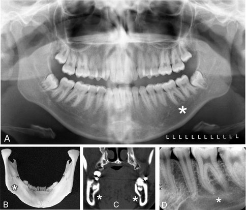
FIG. 11-19 The submandibular fossa (lingual salivary gland depression), a concavity often found on the posterior lingual surface of the mandible. This triangularly shaped area is bounded anatomically by the mylohyoid ridge, the inferior border of the mandibular body, and the posterior border of the mandibular ramus. Asterisk indicates the area of the submandibular fossa on the various images. A, Panoramic image. B, Photograph of the lingual side of a dried mandible. C, Coronal CT scan through the molar region of the mandible. D, Mandibular molar periapical image.
MIDFACIAL REGION
The midface is a complex mixture of bones, air cavities and soft tissues, all of which appear on panoramic images (Figs. 11-20 and 11-21). Individual bones that may appear the panoramic image of the midface include temporal, zygoma, mandible, frontal, maxilla, sphenoid, ethmoid, vomer, nasal, turbinate, and palate; thus, it is somewhat of a misnomer to refer to the midfacial region on the panoramic image as “the maxilla.” Maintaining the discipline and focus of a systemic examination of all aspects of the midfacial images is difficult and critical in the overall examination of the panoramic image.
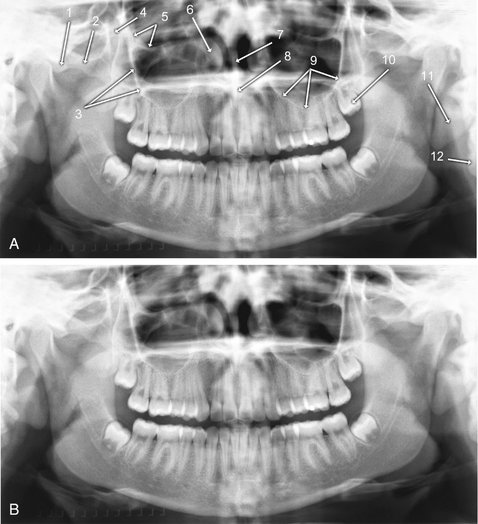
FIG. 11-20 Maxillary, or Mid-facial, Bony Anatomic Structures on the Panoramic Image.
The labeled (A) and unlabeled (B) images are duplicates of the same patient. 1, Articular tubercle, temporal bone. 2, Zygoma. 3, Zygomatic process of maxilla. 4, Pterygomaxillary fissure. 5, Floor of orbit. 6, Anterior aspect if inferior concha. 7, Nasal septum. 8, Anterior nasal spine. 9, Floor of maxillary sinus. 10, Maxillary left third molar (developing). 11, Ear lobe. 12, Cervical vertebral body.
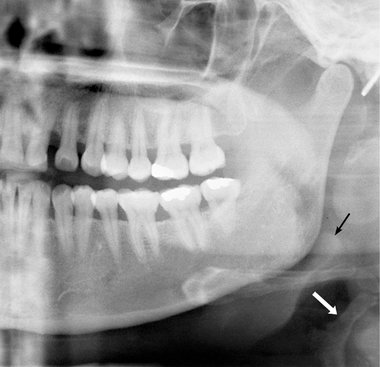
FIG. 11-21 Normal Structures Occasionally Seen in the Neck Area on Panoramic Images.
The white arrow indicates the superior aspect of the thyroid cartilage, which can be mistaken for a vascular calcification. The black arrow indicates the epiglottis. Also note the ear decoration posterior to the mandibular condylar head.
As with the mandible, the maxilla can be compartmentalized into major sites for examination:
• Cortical boundary of the maxilla, including the posterior border and the alveolar ridge
• Zygomatic complex, including inferior and lateral orbital rims, zygomatic process of maxilla, and anterior portion of zygomatic arch
• Temporomandibular joint (already viewed in the mandible, but revisiting important structures is always a good idea in image interpretation)
Examining the cortical outline of the maxilla is a good way to center the examination of the midface. The posterior border of the maxilla extends from the superior portion of the pterygomaxillary fissure down to the tuberosity region and around to the other side. The posterior border of the pterygomaxillary fissure is the pterygoid spine of the sphenoid bone (the anterior border of the pterygoid plates). Occasionally, the sphenoid sinus may extend into this structure. The pterygomaxillary fissure itself has an inverted teardrop appearance; it is very important to identify this area on both sides of the image because maxillary sinus mucoceles and carcinomas will characteristically destroy the posterior maxillary border, which is then manifested as loss of the anterior border of the pterygomaxillary fissure. Also, LeFort fractures of the maxilla by definition involve the pterygoid plate(s), and this will often be initially diagnosed by disturbances of the integrity of the pterygomaxillary fissure on the panoramic image. In fact, this may be the only evidence for such a fracture on the panoramic image. To clarify the three-dimensional anatomy of the pterygomaxillary fissure, Figure 11-22 shows this structure in a dried skull, in an axial CT image, and in the panoramic image.
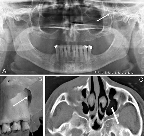
FIG. 11-22 The pterygomaxillary fissure, a space between the posterior surface of the maxilla and the anterior border of the pterygoid plates. A, The inverted teardrop shape of the fissure on a panoramic image (arrow). B, The fissure on a dried skull (arrow). C, The approximate image section of the panoramic image layer through the pterygomaxillary fissure on an axial CT section (white bar).
The maxillary sinuses are usually well visualized on panoramic images. The clinician should identify each of the borders (posterior, anterior, floor, roof) and then note whether they are entirely outlined with cortical bone, roughly symmetric, and comparable in radiographic density. The borders should be present and intact. The medial border of the maxillary sinus is the lateral border of the nasal cavity; however, this interface is not demonstrated on the panoramic image. The superior border, or roof, of the maxillary sinus is the floor of the orbit; this interface is demonstrated on the panoramic image in its most anterior aspect. Although it is useful to compare right and left maxillary sinuses when looking for abnormalities, it is important to remember that the sinuses are frequently nonpathologically asymmetric relative to size, shape, and presence and numbers of septae. The posterior aspect of the sinus is more opaque because of superimposition of the zygoma. Each sinus should be examined for evidence of a mucous retention cyst, mucoperiosteal thickening, and other sinus abnormalities.
The zygomatic complex, or “buttress” of the midface, is a very complex anatomic area, with contributions from the frontal, zygomatic, and maxillary bones. It includes the lateral and inferior orbital rims, the zygomatic process of the maxilla, and the zygomatic arch. The zygomatic process of the maxilla arises over the maxillary first and second molars. The maxillary sinus can pneumatize the zygomatic process of the maxilla up to the zytomaticomaxillary suture. This can result in the appearance of an elliptical, corticated radiolucency in the maxillary sinus, possibly superimposed over the roots of a molar tooth, on a panoramic image. The inferior border of the zygomatic arch extends posteriorly from the inferior portion of the zygomatic process of the maxilla and continues posteriorly to the articular tubercle and glenoid fossa of the temporal bone. The superior border of the zygomatic arch, which curves anterosuperiorly to form the lateral aspect of the lateral orbital rim, should also be noted. The zygomaticotemporal suture lies in the middle of the zygomatic arch and may simulate a fracture if visualized on the image. Additionally, the mastoid air cells will occasionally pneumatize the temporal bone all the way to the zygomaticotemporal suture, giving the glenoid fossa of the TMJ the appearance of having a multilocular, or “soap-bubbly,” radiolucency that is, in fact, a variant of normal.
The nasal fossa may show the nasal septum and inferior concha, including both the bone and its mucosal covering. The conchae, composed of an internal bone, the turbinate, and covering cartilage and mucosa, are seen in a coronal manner in the anterior portion of the image and in a sagittal manner in the posterior portions of the panoramic image. They can appear as very large, homogeneous, soft-tissue densities superimposed over the maxillary sinuses and occasionally the anterior nasopharynx.
SOFT TISSUES
A number of opaque soft tissue structures may be identified on panoramic radiographs (see Figs. 11-20 and 11-21), including the tongue arching across the film under the hard palate, roughly from the region of the right angle of the mandible to the left angle), lip markings (in the middle of the film), the soft palate extending posteriorly from the hard palate (see Fig. 11-18, No. 7) over each ramus, the posterior wall of the oral and nasal pharynx, the nasal septum, ear lobes, nose, and nasolabial folds. Radiolucent airway shadows superimpose on normal anatomic structures and may be demonstrated by the borders of adjacent soft tissues. They include the nasal fossa, nasopharynx, oral cavity, and oropharynx. The epiglottis and thyroid cartilage are often seen in panoramic images. Occasionally the air space between the dorsum of the tongue and the soft palate simulates a fracture through the angle of the mandible.
SUPERIMPOSITIONS AND GHOST IMAGES
Many radiopaque objects out of the image layer superimpose on the images of normal anatomic structures. This results when the x-ray beam projects through a dense object (e.g., an earring, the spinal column, the mandibular ramus, or the hard palate) that is in the path of the x-ray beam but out of the portion of the focal trough being imaged. The object typically appears blurred and projects either over the midline structures, as with the cervical vertebrae, or onto the opposite side of the radiograph with reversed configuration and more cranially positioned than the real structure (see Fig. 11-18). These contralateral images are termed “ghost images,” and they may obscure normal anatomy or be mistaken for pathologic conditions.
DENTITION
Finally, the teeth and supporting alveolar bone should be evaluated. Excessively wide or narrow anterior teeth suggest malposition of the patient in the image layer. Similarly, teeth that are wider on one side than the other suggest that the patient’s sagittal plane was rotated. Although gross caries and periapical and periodontal disease may be evident, subtle disease requires intraoral images for diagnosis. The proximal surfaces of the premolar teeth often overlap, which further interferes with caries interpretation.
One of the strengths of the panoramic image is the demonstration of the complete dentition. Although there is a rare situation where positioning of the patient and of an ectopic tooth place the tooth out of the image layer, all the teeth are generally seen on the image. Thus the interpretation must always include identification of all erupted and developing teeth (Fig. 11-23). The teeth should be examined for gross abnormalities of number, position, and anatomy. Existing dentistry, including endodontic obturations, crowns, and other fixed restorations, should be noted.
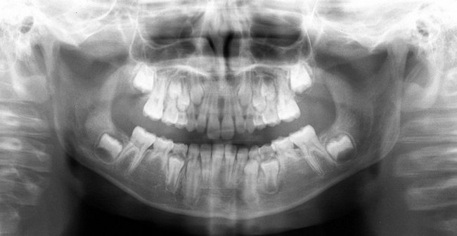
FIG. 11-23 Panoramic image showing late mixed dentition of an 11-year-old patient. The panoramic image can be useful in identifying the presence or absence, as well as developmental status, of the permanent dentition. In this patient, the mandibular second premolars are congenitally absent, and the mandibular deciduous second molars are not undergoing root resorption, indicating that they will be retained. The permanent canines, second molars, and first and second premolars are in various stages of mineralization, with most of them beginning to erupt.
It is particularly important to closely examine impacted third molars. Their orientation, the numbers and configurations of the roots, the relationships of the tooth components to critical anatomic structures such as the mandibular canal, the floor and posterior wall of the maxillary sinus, the maxillary tuberosity, and adjacent teeth, and the presence of abnormalities in the pericoronal or periradicular bone must be carefully studied. Suspected abnormalities of the dentition seen on panoramic images will generally require intraoral imaging for a more definitive demonstration of the area.
Brooks, SL, Brand, JW, Gibbs, SJ, et al. Imaging of the temporomandibular joint: a position paper of the American Academy of Oral and Maxillofacial Radiology. Oral Surg Oral Med Oral Pathol Oral Radiol Endod. 1997;83:609–618.
Chomenko, AG. Atlas for maxillofacial pantomographic interpretation. Chicago: Quintessence; 1985.
Farman AG, ed. Panoramic radiology: seminars on maxillofacial imaging and interpretation. Berlin: Springer, 2007.
Langland, OE, Langlais, RP, McDavid, WD, et al. Panoramic radiology, ed 2. Philadelphia: Lea & Febiger; 1989.
Moore WE, editor: Successful panoramic radiography: KODAK Dental Radiography Series (2001): www.kodakdental.com/documentation/film/N-406SuccPanRad.pdf. Accessed February 20, 2008.
Numata, H. Consideration of the parabolic radiography of the dental arch. J Shimazu Stud. 1933;10:13.
Paatero, YV. The use of a mobile source of light in radiography. Acta Radiol. 1948;29:221.
Paatero, YV. A new tomographic method for radiographing curved outer surfaces. Acta Radiol. 1949;32:177.