X-Ray Film, Intensifying Screens, and Grids
A beam of x-ray photons that passes through the dental arches is reduced in intensity (attenuated) by absorption and scattering of photons out of the primary beam. The pattern of the photons that exits the subject, the remnant beam, conveys information about the structure and composition of the absorber. For this information to be useful diagnostically, the remnant beam must be recorded on an image receptor. The image receptor most often used in dental radiography is x-ray film. This chapter describes x-ray film and its properties and the use of intensifying screens and grids to modify radiographic images. Digital radiographic systems, which also may be used to make radiographs, are described in Chapter 7.
X-Ray Film
X-ray film has two principal components: emulsion and base. The emulsion, which is sensitive to x rays and visible light, records the radiographic image. The base is a plastic supporting material onto which the emulsion is coated (Fig. 5-1).
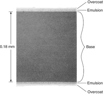
FIG. 5-1 Scanning electron micrograph of Kodak InSight dental x-ray film (original magnification 300×). Note the overcoat, emulsion, and base on this double-emulsion film. (Courtesy Carestream Health, Inc., exclusive manufacturer of Kodak dental systems.)
Emulsion
The two principal components of emulsion are silver halide grains, which are sensitive to x radiation and visible light, and a vehicle matrix in which the crystals are suspended. The silver halide grains are composed primarily of crystals of silver bromide. The composition of a dental film emulsion is shown in Table 5-1. Iodide is added to Ultra-Speed film because its large diameter (compared with bromine) disrupts the regularity of the silver bromide crystal structure, thereby increasing its sensitivity to x radiation. Iodide is not used in InSight film. The photosensitivity of the silver halide crystals also depends on the presence of trace amounts of a sulfur-containing compound. In addition, trace amounts of gold are sometimes added to silver halide crystals to improve their sensitivity.
TABLE 5-1
Typical Coating Weights per Film Side (mg/cm2)*
*Courtesy Carestream Health, Inc., exclusive manufacturer of Kodak dental systems.
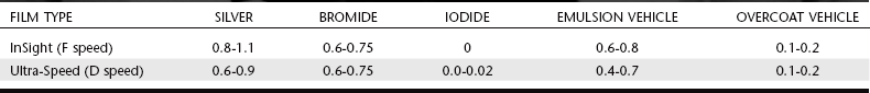
The silver halide grains in InSight film are flat, tabular crystals with a mean diameter of about 1.8 μm (Fig. 5-2). Ultra-Speed film is composed of globular-shaped crystals about 1 μm in diameter. The tabular grains of the InSight film are oriented parallel with the film surface to offer a large cross-sectional area to the x-ray beam (Fig. 5-3). As a result, InSight film requires only about half the exposure of Ultra-Speed film.
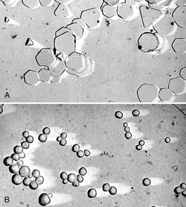
FIG. 5-2 Scanning electron micrographs of emulsion comparing flat tabular silver bromide crystals of InSight film (A) with globular silver halide crystals of Ultra-Speed film (B). (Courtesy Carestream Health, Inc., exclusive manufacturer of Kodak dental systems.)

FIG. 5-3 Cross-sectional electron microscopic image of emulsion of InSight film (A) and Ultra-Speed film (B). Note that the orientation of the tabular crystals in the InSight film is essentially parallel to the film surface to increase the exposure surface area of the crystals to the x-ray beam. (Courtesy Carestream Health, Inc., exclusive manufacturer of Kodak dental systems.)
In the manufacture of film, the silver halide grains are suspended in a surrounding vehicle that is applied to both sides of the supporting base. The vehicle, composed of gelatinous and nongelatinous materials, keeps the silver halide grains evenly dispersed. To ensure good adhesion of the emulsion to the film base, a thin layer of adhesive material is added to the base before the emulsion is applied. During film processing, the vehicle absorbs the processing solutions, allowing the chemicals to reach and react with the silver halide grains. An additional layer of vehicle is added to the film emulsion as an overcoat; this barrier helps protect the film from damage by scratching, contamination, or pressure from rollers when an automatic processor is used.
Film emulsions are sensitive to both x-ray photons and visible light. Film intended to be exposed by x rays is called direct exposure film. All intraoral dental film is direct exposure film. Screen film, which is sensitive to visible light, is used with intensifying screens that emit visible light. Screen film and intensifying screens are used for extraoral projections such as panoramic and skull radiographs. Intensifying screens are described later in this chapter.
Base
The function of the film base is to support the emulsion. The base must have the proper degree of flexibility to allow easy handling of the film. The base for dental x-ray film is 0.18 mm thick and is made of polyester polyethylene terephthalate. The film base is uniformly translucent and casts no pattern on the resultant radiograph. Some think that a base with a slight blue tint improves viewing of diagnostic detail. The film base must also withstand exposure to processing solutions without becoming distorted.
INTRAORAL X-RAY FILM
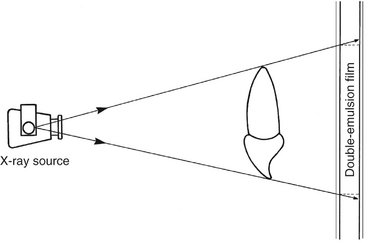
A number of manufacturers around the world make intraoral dental x-ray film. In each case the film is made as a double-emulsion film, that is, coated with an emulsion on each side of the base. With a double layer of emulsion, less radiation can be used to produce an image. Direct exposure film is used for intraoral examinations because it provides higher-resolution images than screen-film combinations. Some diagnostic tasks, such as detection of incipient caries or early periapical disease, require this higher resolution.
One corner of each dental film has a small, raised dot that is used for film orientation (Fig. 5-4). The manufacturer orients the film in the packet so that the convex side of the dot is toward the front of the packet and faces the x-ray tube. The side of the film with the depression is thus oriented toward the patient’s tongue. After the film has been exposed and processed, the dot is used to identify the image as showing the patient’s right or left side. When the films are mounted with the images of the teeth in the anatomic position, each film is first oriented with the convex side of the dot toward the viewer. Then, on the basis of the features of the teeth and anatomic landmarks in the adjacent bone, the films are arranged in their normal sequential relationship in the mount.
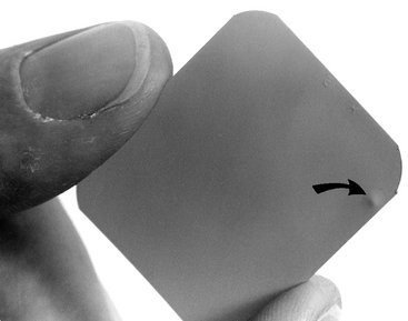
FIG. 5-4 The raised film dot (arrow) indicates the tube side of the film and identifies the patient’s right and left sides.
Intraoral x-ray film packets contain either one or two sheets of film (Fig. 5-5). When double-film packs are used, the second film serves as a duplicate record that can be sent to insurance companies or to a colleague. The film is encased in a protective black paper wrapper and then in an outer white paper or plastic wrapping, which is resistant to moisture. The outer wrapping clearly indicates the location of the raised dot and identifies which side of the film should be directed toward the x-ray tube.
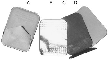
FIG. 5-5 Moisture- and light-proof packet (A) contains an opening tab on the side opposite the tube. Inside is a sheet of lead foil (B) and a black, lightproof, interleaf paper wrapper (C) that is folded around the film (D). Film is packaged with one or two sheets of film.
Between the wrappers in the film packet is a thin lead foil backing with an embossed pattern. The foil is positioned in the film packet behind the film, away from the tube. This lead foil serves several purposes. It shields the film from backscatter (secondary) radiation, which fogs the film and reduces subject contrast (image quality). It also reduces patient exposure by absorbing some of the residual x-ray beam. Perhaps most important, however, is the fact that if the film packet is placed backward in the patient’s mouth so that the tube side of the film is facing away from the x-ray machine, the lead foil will be positioned between the subject and the film. In this circumstance most of the radiation is absorbed by the lead foil and the resulting radiograph is light and shows the embossed pattern in the lead foil. This combination of a light film with the characteristic pattern indicates that the film packet was put in the patient’s mouth backward and that the patient’s right side–left side designation indicated by the film dot was reversed.
Because intraoral direct exposure film packets have several uses and are used in large adults and small children, the film packets are made in a variety of sizes. The composition of the film is identical in each case.
Periapical View
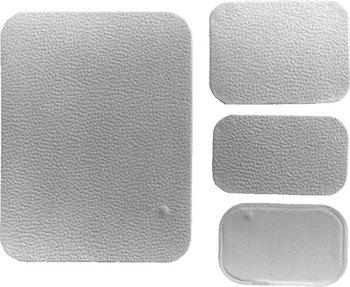
Periapical views are used to record the crowns, roots, and surrounding bone. Film packs come in three sizes: 0 for small children (22 × 35 mm); 1, which is relatively narrow and used for views of the anterior teeth (24 × 40 mm); and 2, the standard film size used for adults (31 × 41 mm) (Fig. 5-6).
Bitewing View
Bitewing (interproximal) views are used to record the coronal portions of the maxillary and mandibular teeth in one image. They are useful for detecting interproximal caries and evaluating the height of alveolar bone. Size 2 film is normally used in adults; the smaller size 1 is preferred in children. In small children, size 0 may be used. A relatively long size 3 also is available.
Bitewing films often have a paper tab projecting from the middle of the film on which the patient bites to support the film (Fig. 5-7). This tab is rarely visualized and does not interfere with the diagnostic quality of the image. Film-holding instruments for bitewing projections also are available.
Occlusal View
Occlusal film is more than three times larger than size 2 film (57 × 76 mm) (see Fig. 5-6). It is used to show larger areas of the maxilla or mandible than may be seen on a periapical film. These films also are used to obtain right-angle views to the usual periapical view. The name derives from the fact that the film usually is held in position by having the patient bite lightly on it to support it between the occlusal surfaces of the teeth (see Chapter 9).
SCREEN FILM
The extraoral projections used most frequently in dentistry are the panoramic, cephalometric, and other skull views. For these projections and for virtually all other extraoral radiography, screen film is used with intensifying screens (described later in this chapter) to reduce patient exposure. Screen film is different from dental intraoral film. It is designed to be sensitive to visible light because it is placed between two intensifying screens when an exposure is made. The intensifying screens absorb x rays and emit visible light, which exposes the screen film. Silver halide crystals are inherently sensitive to ultraviolet (UV) and blue light (300 to 500 nm) and thus are sensitive to screens that emit UV and blue light. When film is used with screens that emit green light, the silver halide crystals are coated with sensitizing dyes to increase absorption. Because the properties of intensifying screens vary, the dentist should use the appropriate screen-film combination recommended by the screen and film manufacturer so that the emission characteristics of the screen match the absorption characteristics of the film.
Several general types of screen film are suitable for extraoral radiography. Several manufacturers supply high-contrast, medium-speed film suitable for skull radiography. Other films are available that are faster (i.e., they require less radiation exposure), but these provide less image detail. Such films should be considered for panoramic radiography when fine image detail is not available because of movement of the x-ray tube head during the exposure.
Another type of film provides less contrast and a wider latitude. This type reveals a wide range of densities and is most suitable for cephalometric radiography, when both bony and soft tissue details are desired.
Contemporary screen films use tabular-shaped (flat) grains of silver halide (Fig. 5-8) to capture the image. The tabular grains are oriented with their relatively large, flat surfaces facing the radiation source, providing a larger cross-section (target) and resulting in increased speed without loss of sharpness. In addition, green-sensitizing dyes are added to the surface of the tabular grains, increasing their light-absorbing capability. Some manufacturers add an absorbing dye in the film emulsion to reduce crossover of light from one screen to the film emulsion on the opposite side. This increases the sharpness of the image.
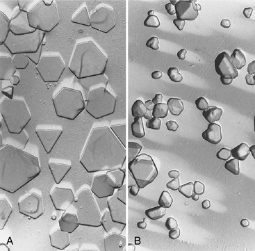
FIG. 5-8 T grains of silver halide in an emulsion of T-Mat film (A) are larger and flatter than the smaller, thicker crystals in an emulsion of conventional film (B). Note that the flat surfaces of the T grains are oriented parallel with the film surface, facing the radiation source. (Courtesy Carestream Health, Inc., exclusive manufacturer of Kodak dental systems.)
Intensifying Screens
Early in the history of radiography, scientists discovered that various inorganic salts or phosphors fluoresce (emit visible light) when exposed to an x-ray beam. The intensity of this fluorescence is proportional to the x-ray energy absorbed. These phosphors have been incorporated into intensifying screens for use with screen film. The sum of the effects of the x rays and the visible light emitted by the screen phosphors exposes the film in an intensifying cassette.
FUNCTION
The presence of intensifying screens creates an image receptor system that is 10 to 60 times more sensitive to x rays than the film alone. Consequently, use of intensifying screens means a substantial reduction in the dose of x radiation to which the patient is exposed. Intensifying screens are used with films for virtually all extraoral radiography, including panoramic, cephalometric, and skull projections. In general, the resolving power of screens is related to their speed: the slower the speed of a screen, the greater its resolving power and vice versa. Intensifying screens are not used intraorally with periapical or occlusal films because their use would reduce the resolution of the resulting image below that necessary for diagnosis of much dental disease.
COMPOSITION
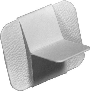
Intensifying screens are made of a base supporting material, a phosphor layer, and a protective polymeric coat (Fig. 5-9). In all dental applications, intensifying screens are used in pairs, one on each side of the film, and they are positioned inside a cassette (Fig. 5-10). The purpose of a cassette is to hold each intensifying screen in contact with the x-ray film to maximize the sharpness of the image. Most cassettes are rigid, but they may be flexible.
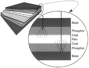
FIG. 5-9 The image on the left shows a schematic of two intensifying screens (shades of gray) enclosing a film (white). The detailed view on the right shows x-ray photons entering at the top, traveling through the base, and striking phosphors in the base. The phosphors emit visible light, exposing the film. Some visible light photons may reflect off the reflecting layer of the base.
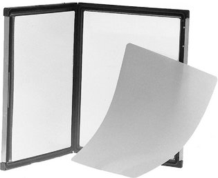
FIG. 5-10 Cassette for 8- × 10-inch film. When the cassette is closed, the film is supported in close contact between two intensifying screens.
Base
The base material of most intensifying screens is some form of polyester plastic that is about 0.25 mm thick. The base provides mechanical support for the other layers. In some intensifying screens the base also is reflective; thus, it reflects light emitted from the phosphor layer back toward the x-ray film. This has the effect of increasing the light emission of the intensifying screen. However, it also results in some image “unsharpness” because of the divergence of light rays reflected back to the film. Some fine detail intensifying screens omit the reflecting layer to improve image sharpness. In other intensifying screens the base is not reflective, and a separate coating of titanium dioxide is applied to the base material to serve as a reflecting layer.
Phosphor Layer
The phosphor layer is composed of phosphorescent crystals suspended in a polymeric binder. When the crystals absorb x-ray photons, they fluoresce (see Fig. 5-9). The phosphor crystals often contain rare earth elements, most commonly lanthanum and gadolinium. Their fluorescence can be increased by the addition of small amounts of elements such as thulium, niobium, or terbium. Common phosphor combinations used in intensifying screens are shown in Table 5-2.
TABLE 5-2
Rare Earth Elements Used in Intensifying Screens
| EMISSION | PHOSPHOR |
| Green | Gadolinium oxysulfide, terbium activated |
| Blue and UV | Yttrium tantalite, niobium activated |
Some rare earth compounds are efficient phosphors. In the energy range typically used in dental radiography, a pair of rare earth intensifying screens absorbs about 60% of the photons that reach the cassette after passing through a patient. These phosphors are about 18% efficient in converting this x-ray energy to visible light. Rare earth screens convert each absorbed x-ray photon into about 4000 lower-energy, visible light (green or blue) photons. These visible photons then expose the film.
Different phosphors fluoresce in different portions of the spectrum. For example, light emission from Kodak Lanex (Fig. 5-11) rare earth intensifying screens ranges from 375 to 600 nm and peaks sharply at 545 nm (green). Figure 5-10 shows the spectral emission of a rare earth screen and the spectral sensitivity of an appropriate film. Other intensifying screens have a major peak at 350 nm (UV) and another at 450 nm (blue). It is important to match green-emitting screens with green-sensitive films and blue-emitting screens with blue-sensitive films.
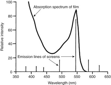
FIG. 5-11 Relative sensitivity of Kodak T-Mat film (continuous line) and emission lines of a Kodak Lanex and Ektavision screens (gadolinium oxysulfide, terbium activated). Intensifying screens emit light as a series of relatively narrow line emissions. The maximal emission of the screen at 545 nm corresponds well to a high-sensitivity region of the film. (Data courtesy Carestream Health, Inc., exclusive manufacturer of Kodak dental systems.)
The speed and resolution of a screen depends on many factors, including the following:
• Phosphor type and phosphor conversion efficiency
• Thickness of phosphor layer and coating weight (amount of phosphor/unit volume)
• Presence of reflective layer
• Presence of light-absorbing dye in phosphor binder or protective coating
Fast screens have large phosphor crystals and efficiently convert x-ray photons to visible light but produce images with lower resolution. As the size of the crystals or the thickness of the screen decreases, the speed of the screen also declines, but image sharpness increases. Fast screens also have a thicker phosphor layer and a reflective layer, but these properties also decrease sharpness. In deciding on the combination to use, the practitioner must consider the resolution requirements of the task for which the image will be used. Most dental extraoral diagnostic tasks can be accomplished with screen-film combinations that have a speed of 400 or faster.
Protective Coat
A protective polymer coat (up to 15 μm thick) is placed over the phosphor layer to protect the phosphor and to provide a surface that can be cleaned. The intensifying screens should be kept clean because any debris, spots, or scratches may cause light spots on the resultant radiograph.
Image Characteristics
Processing an exposed x-ray film causes it to become dark in the exposed area. The degree and pattern of film darkening depend on numerous factors, including the energy and intensity of the x-ray beam, composition of the subject imaged, film emulsion used, and characteristics of film processing. This section describes the major imaging characteristics of x-ray film.
RADIOGRAPHIC DENSITY
When a film is exposed by an x-ray beam (or by light, in the case of screen-film combinations) and then processed, the silver halide crystals in the emulsion that were struck by the photons are converted to grains of metallic silver. These silver grains block the transmission of light from a viewbox and give the film its dark appearance. The overall degree of darkening of an exposed film is referred to as radiographic density. This density can be measured as the optical density of an area of an x-ray film where:
where Io is the intensity of incident light (e.g., from a viewbox) and It is the intensity of the light transmitted through the film. Thus the measurement of film density also is a measure of the opacity of the film. With an optical density of 0, 100% of the light is transmitted; with a density of 1, 10% of the light is transmitted; with a density of 2, 1% of the light is transmitted, and so on.
A plot of the relationship between film optical density and exposure is called a characteristic curve (Fig. 5-12). It usually is shown as the relationship between the optical density of the film and the logarithm of the corresponding exposure. As exposure of the film increases, its optical density increases. A film is of greatest diagnostic value when the structures of interest are imaged on the relatively straight portion of the graph, between 0.6 and 3.0 optical density units. The characteristic curves of films reveal much information about film contrast, speed, and latitude.
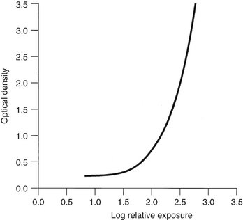
FIG. 5-12 Characteristic curve of direct exposure film. The contrast (slope of the curve) is greater in the high-density region than in the low-density region.
An unexposed film, when processed, shows some density. This is caused by the inherent density of the base and added tint and the development of unexposed silver halide crystals. This minimal density is called gross fog, or base plus fog. The optical density of gross fog typically is 0.2 to 0.3.
Radiographic density is influenced by exposure and the thickness and density of the subject.
Exposure
The overall film density depends on the number of photons absorbed by the film emulsion. Increasing the milliamperage (mA), peak kilovoltage (kVp), or exposure time increases the number of photons reaching the film and thus increases the density of the radiograph. Reducing the distance between the focal spot and film also increases film density.
Subject Thickness
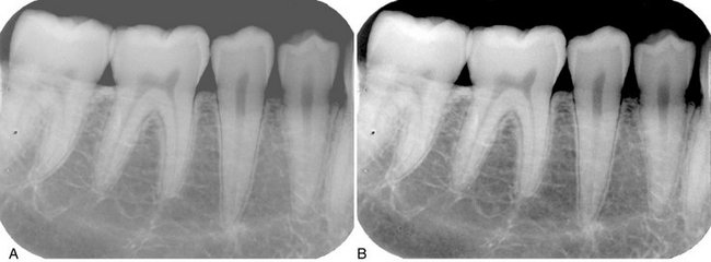
The thicker the subject, the more the beam is attenuated and the lighter the resultant image (Fig. 5-13). If exposure factors intended for adults are used on children or edentulous patients, the resultant films are dark because a smaller amount of absorbing tissue is in the path of the x-ray beam. The dentist should vary exposure (either kVp or time) according to the patient’s size to produce radiographs of optimal density.
Subject Density
Variations in the density of the subject exert a profound influence on the image. The greater the density of a structure within the subject, the greater the attenuation of the x-ray beam directed through that subject or area. In the oral cavity the relative densities of various natural structures, in order of decreasing density, are enamel, dentin and cementum, bone, muscle, fat, and air. Metallic objects (e.g., restorations) are far denser than enamel and hence better absorbers. Because an x-ray beam is differentially attenuated by these absorbers, the resultant beam carries information that is recorded on the radiographic film as light and dark areas. Dense objects (which are strong absorbers) cause the radiographic image to be light and are said to be radiopaque. Objects with low densities are weak absorbers. They allow most photons to pass through, and they cast a dark area on the film that corresponds to the radiolucent object.
RADIOGRAPHIC CONTRAST
Radiographic contrast is a general term that describes the range of densities on a radiograph. It is defined as the difference in densities between light and dark regions on a radiograph. Thus an image that shows both light areas and dark areas has high contrast. This also is referred to as a short gray scale of contrast because few shades of gray are present between the black and white images on the film. A radiographic image composed only of light gray and dark gray zones has low contrast, also referred to as having a long gray scale of contrast (Fig. 5-14). The radiographic contrast of an image is the result of the interplay of subject contrast, film contrast, and scattered radiation.
Subject Contrast
Subject contrast is the range of characteristics of the subject that influences radiographic contrast. It is influenced largely by the subject’s thickness, density, and atomic number. The subject contrast of a patient’s head and neck exposed in a lateral cephalometric view is high. The dense regions of the bone and teeth absorb most of the incident radiation, whereas the less dense soft tissue facial profile transmits most of the radiation.
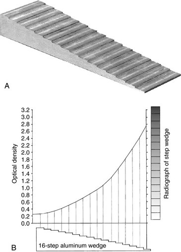
Subject contrast also is influenced by beam energy and intensity. The energy of the x-ray beam, selected by the kVp, influences image contrast. Figure 5-15 shows an aluminum step wedge exposed to x-ray beams of differing energies. Because increasing the kVp increases the overall density of the image, the exposure time has been adjusted so that the density of the middle step in each case is comparable. As the kVp of the x-ray beam increases, subject contrast decreases. Similarly, when relatively low kVp energies are used, subject contrast increases. Most clinicians select a kVp in the range of 70 to 80. At higher values the exposure time is reduced, but the loss of contrast may be objectionable because subtle changes may be obscured.
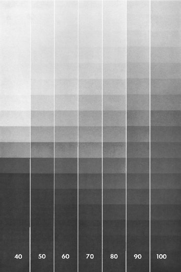
FIG. 5-15 Radiographs of a step wedge made at 40 to 100 kVp. As the kVp increases, the mA is reduced to maintain the uniform middle-step density. Note the long gray scale (low contrast) with high kVp. (Courtesy Carestream Health, Inc., exclusive manufacturer of Kodak dental systems.)
Changing the time or mA of the exposure (and holding the kVp constant) also influences subject contrast. If the film is excessively light or dark, contrast of anatomic structures is diminished. Subtle changes in the mA may also slightly change subject contrast by changing the location of the radiographed structures on the characteristic curve, as described previously.
Film Contrast
Film contrast describes the capacity of radiographic films to display differences in subject contrast, that is, variations in the intensity of the remnant beam. A high-contrast film reveals areas of small difference in subject contrast more clearly than does a low-contrast film. Film contrast usually is measured as the average slope of the diagnostically useful portion of the characteristic curve (Fig. 5-16): the greater the slope of the curve in this region, the greater the film contrast. In this illustration, film A has a higher contrast than film B. When the slope of the curve in the useful range is greater than 1, the film exaggerates subject contrast. This desirable feature, which is found in most diagnostic film, allows visualization of structures that differ only slightly in density. For example, the remnant beam in the region of a tooth pulp chamber will be more intense (greater exposure) than the beam from the surrounding enamel crown. A high-contrast film will show a greater contrast (difference in optical density) between these structures than will a low-contrast film. Films used with intensifying screens typically have a slope in the range of 2 to 3.
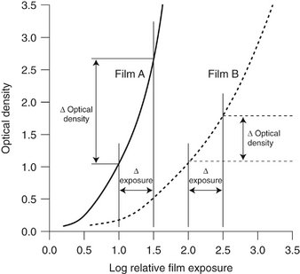
FIG. 5-16 Characteristic curves of two films demonstrating the greater inherent contrast of film A compared with film B. The slope of film A is greater than that of film B; thus film A shows a greater change in optical density than film B for a constant change in exposure. The fact that film A is faster than film B in this figure is unrelated to film contrast.
As can be seen in Figure 5-12, film contrast also depends on the density range being examined. With dental direct-exposure film, the slope of the curve continually increases with increasing exposure. As a result, properly exposed films have more contrast than do underexposed (light) films.
Film processing is another factor that influences film contrast. Film contrast is maximized by optimal film processing conditions. Mishandling of the film through incomplete or excessive development diminishes contrast of anatomic structures. Improper handling of film, such as storage at too high a temperature, exposure to excessively bright safelights, or light leaks in the darkroom, also degrades film contrast.
Fog on an x-ray film results in increased film density arising from causes other than exposure to the remnant beam. Film contrast is reduced by the addition of this undesirable density. Common causes of film fog are improper safelighting, storage of film at too high a temperature, and development of film at an excessive temperature or for a prolonged period. Film fog can be reduced by proper film processing and storage.
Scattered Radiation
Scattered radiation results from photons that have interacted with the subject by Compton or coherent interactions. These interactions cause the emission of photons that travel in directions other than that of the primary beam. The consequent scattered radiation causes fogging of a radiograph, an overall darkening of the image that results in loss of radiographic contrast. In most dental applications the best means of reducing scattered radiation are to (1) use a relatively low kVp, (2) collimate the beam to the size of the film to prevent scatter from an area outside the region of the image, and (3) use grids in extraoral radiography.
RADIOGRAPHIC SPEED
Radiographic speed refers to the amount of radiation required to produce an image of a standard density. Film speed frequently is expressed as the reciprocal of the exposure (in Roentgens) required to produce an optical density of 1 above gross fog. A fast film requires a relatively low exposure to produce a density of 1, whereas a slower film requires a longer exposure for the processed film to have the same density. Film speed is controlled largely by the size of the silver halide grains and their silver content.
The speed of dental intraoral x-ray film is indicated by a letter designating a particular group (Table 5-3). The fastest dental film currently available has a speed rating of F. Only films with a D or faster speed rating are appropriate for intraoral radiography. Currently the types of film used most often in the United States are Kodak Ultra-Speed (group D) and Kodak InSight (group E or F, depending on processing conditions). InSight film is preferred because it requires only about half the exposure of Ultra-Speed film and offers comparable contrast and resolution. F-speed film is faster than the D-speed film because tabular crystal grains are used in the emulsion of F-speed film. The characteristic curves in Figure 5-17 show that InSight film (curve on the left) is faster than Ultra-Speed film (curve on the right) because less exposure is required to produce the same level of density although the two films have similar contrast.
TABLE 5-3
Intraoral Film Speed Classification
| FILM SPEED GROUP | SPEED RANGE (RECIPROCAL ROENTGENS*) |
| C | 6-12 |
| D | 12-24 |
| E | 24-48 |
| F | 48-96 |
*Reciprocal Roentgens are the reciprocal of the exposure in Roentgens required to obtain a film with an optical density of 1.0 above base plus fog after processing.
From National Council on Radiation Protection and Measurements, Report No. 145, Appendix E, 2004.
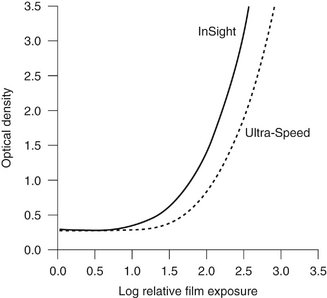
FIG. 5-17 Characteristic curves for InSight and Ultra-Speed film. InSight film is faster and has essentially the same contrast as Ultra-Speed film. (Courtesy Carestream Health, Inc., exclusive manufacturer of Kodak dental systems.)
Although film speed can be increased slightly by processing the film at a higher temperature, this is achieved at the expense of increased film fog and graininess. Processing in depleted solutions can lower the effective speed. It is always preferable to use fresh processing solutions and follow the recommended processing time and temperature.
FILM LATITUDE
Film latitude is a measure of the range of exposures that can be recorded as distinguishable densities on a film. A film optimized to display a wide latitude can record a subject with a wide range of subject contrast. A film with a characteristic curve that has a long straight-line portion and a shallow slope has a wide latitude (Fig. 5-18). As a consequence, wide variations in the amount of radiation exiting the subject can be recorded. Films with a wide latitude have lower contrast (i.e., a long gray scale) than do films with a narrow latitude. Wide-latitude films are useful when both the osseous structures of the skull and the soft tissues of the facial region must be recorded.
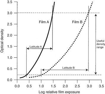
FIG. 5-18 Characteristic curves for two films demonstrating greater inherent latitude of film B compared with film A. The slope of film B is less steep than that of film A; therefore film B records a greater range of exposures within the useful density range than does film A.
To some extent the operator can modify the latitude of an image. A high kVp produces images with a wide latitude and low contrast. Reduced exposure produces a somewhat lighter image and shows a slightly wider range of anatomic structures with lower contrast. Wide-latitude film is recommended for imaging structures with a wide range of subject densities.
RADIOGRAPHIC NOISE
Radiographic noise is the appearance of uneven density of a uniformly exposed radiographic film. It is seen on a small area of film as localized variations in density. The primary causes of noise are radiographic mottle and radiographic artifact. Radiographic mottle is uneven density resulting from the physical structure of the film or intensifying screens. Radiographic artifacts are defects caused by errors in film handling, such as fingerprints or bends in the film, or errors in film processing, such as splashing developer or fixer on a film or marks or scratches from rough handling.
On intraoral dental film, mottle may be seen as film graininess, which is caused by the visibility of silver grains in the film emulsion, especially when magnification is used to examine an image. Film graininess is most evident when high-temperature processing is used.
Radiographic mottle is also evident when the film is used with fast intensifying screens. Two important causes of the phenomenon are quantum mottle and screen structure mottle. Quantum mottle is caused by a fluctuation in the number of photons per unit of the beam cross-sectional area absorbed by the intensifying screen. Quantum mottle is most evident when fast film-screen combinations are used. Under these conditions the relative nonuniformity of the beam is highest. The longer exposures required by slower film-screen combinations tend to average out the beam pattern and thereby reduce quantum mottle. Screen structure mottle is graininess caused by screen phosphors. It is most evident when fast screens with large crystals are used.
RADIOGRAPHIC BLURRING
Sharpness is the ability of a radiograph to define an edge precisely (e.g., the dentin-enamel junction, a thin trabecular plate). Resolution, or resolving power, is the ability of a radiograph to record separate structures that are close together. It usually is measured by radiographing an object made up of a series of thin lead strips with alternating radiolucent spaces of the same thickness. The groups of lines and spaces are arranged in the test target in order of increasing numbers of lines and spaces per millimeter (Fig. 5-19). The resolving power is measured as the highest number of line pairs (a line pair being the image of an absorber and the adjacent lucent space) per millimeter that can be distinguished on the resultant radiograph when examined with low-power magnification. Typically, panoramic film-screen combinations can resolve about five line pairs per millimeter; periapical film, which has better resolving power, can delineate clearly more than 20 line pairs per millimeter.
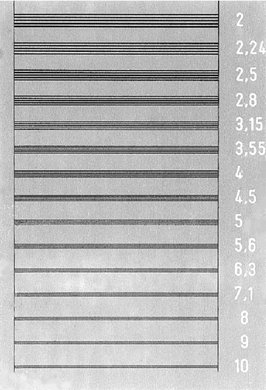
FIG. 5-19 Radiograph of a resolving power target consisting of groups of radiopaque lines and radiolucent spaces. Numbers at each group indicate the line pairs per millimeter represented by the group.
Radiographic blur is caused by image receptor (film and screen) blurring, motion blurring, and geometric blurring.
Image Receptor Blurring
With intraoral dental x-ray film, the size and number of the silver grains in the film emulsion determines image sharpness: the finer the grain size, the finer the sharpness. In general, slow-speed films have fine grains and faster films have larger grains.
Use of intensifying screens in extraoral radiography has an adverse effect on image sharpness. Some degree of sharpness is lost because visible light and UV radiation emitted by the screen spread out beyond the point of origin and expose a film area larger than the phosphor crystal (see Fig. 5-9). The spreading light causes a blurring of fine detail on the radiograph. Intensifying screens with large crystals are relatively fast, but image sharpness is diminished. Furthermore, fast intensifying screens have a relatively thick phosphor layer, which contributes to dispersion of light and loss of image sharpness. Diffusion of light from a screen can be minimized and image sharpness maximized by ensuring as close a contact as possible between the intensifying screen and the film.
The presence of an image on each side of a double-emulsion film also causes a loss of image sharpness through parallax (Fig. 5-20). Parallax results from the apparent change in position or size of a subject when it is viewed from different perspectives. Because dental film has a double coating of emulsion and the x-ray beam is divergent, the images recorded on each emulsion vary slightly in size. In intraoral images, the effect of parallax on image sharpness is unimportant but is most apparent when wet films are viewed. Under these conditions the emulsion is swollen with water and the loss of image sharpness caused by parallax is more evident. When intensifying screens are used, parallax distortion contributes to image unsharpness because light from one screen may cross the film base and reach the emulsion on the opposite side. This problem can be solved by incorporating dyes into the base that absorb the light emitted by the screens.
Motion Blurring
Image sharpness also can be lost through movement of the film, subject, or x-ray source during exposure. Movement of the x-ray source in effect enlarges the focal spot and diminishes image sharpness. Patient movement can be minimized by stabilizing the patient’s head with the chair headrest during exposure. Use of a higher mA and kVp and correspondingly shorter exposure times also helps resolve this problem.
Geometric Blurring
Several geometric factors influence image sharpness. Loss of image sharpness results in part because photons are not emitted from a point source (focal spot) on the target in the x-ray tube. The larger the focal spot, the greater the loss of image sharpness. Also, image sharpness is improved by increasing the distance between the focal spot and the object and reducing the distance between the object and the image receptor. Various means of optimizing projection geometry are discussed in Chapter 4.
IMAGE QUALITY
Image quality describes the subjective judgment by the clinician of the overall appearance of a radiograph. It combines the features of density, contrast, latitude, sharpness, resolution, and perhaps other parameters. Various mathematic approaches have been used to evaluate these parameters further, but a thorough discussion of them is beyond the scope of this text. The detective quantum efficiency (DQE) is a basic measure of the efficiency of an imaging system. It encompasses image contrast, blur, speed, and noise. Often a system can be optimized for one of these parameters, but this usually is achieved at the expense of others. For instance, a fast system typically has a high level of noise. Even with these and other sophisticated approaches, however, more information is needed for complete understanding of all the factors responsible for the subjective impression of image quality.
Grids
When an x-ray beam strikes a patient, many of the incident photons undergo Compton interactions and produce scattered photons. Typically the number of scattered photons in the remnant beam that reach the film is two to four times the number of primary photons that do not undergo absorption. The amount of scattered radiation increases with increasing subject thickness, field size, and kVp (energy of the x-ray beam). These scattered photons produce fog on the film and reduce the subject contrast.
FUNCTION
The function of a grid is to reduce the amount of scattered radiation exiting a subject that reaches the film. The grid, which is placed between the subject and the film, preferentially removes the scattered radiation and spares primary photons; this reduces nonimaging exposure and increases subject contrast.
COMPOSITION
A grid is composed of alternating strips of a radiopaque material (usually lead) and strips of radiolucent material (often plastic). The diagram in Figure 5-21 shows the interaction between a grid and an x-ray beam. When secondary photons generated in the subject are scattered toward the film, they usually are absorbed by the radiopaque material in the grid. This occurs because the direction of the scattered photons deviates from that of the primary beam, and consequently they cannot pass through the parallel plates of the grid. Focused grids are used most often. In a focused grid the strips of radiopaque material are all directed toward a common point, the focal spot of the x-ray tube, some distance away. Because the lead strips are angled toward the focal spot, their direction coincides with the paths of diverging photons in the primary x-ray beam. The lead strips absorb the scattered photons as their paths diverge from those of the primary photons. A focused grid can be used only within a range of distances from the focal spot where the alignment of lead strips closely coincides with the path of the diverging x-ray beam. The range of distances is specified on the grid.
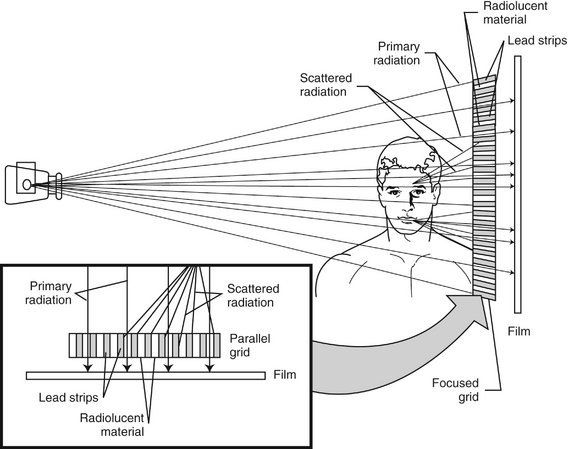
FIG. 5-21 An x-ray grid absorbs scattered x-ray photons from the primary beam and prevents them from fogging the film. In a focused grid the absorber plates are angled toward the anode; in a parallel grid the absorber plates are parallel.
Grids are manufactured with a varying number of line pairs of absorbers and radiolucent spaces per inch. Grids with 80 or more line pairs per inch do not show objectionable grid lines on the image. The ratio of grid thickness to the width of the radiolucent spacer is known as the grid ratio. The higher the grid ratio, the more effectively scattered radiation is removed from the x-ray beam. Grids with a ratio of 8 or 10 are preferred.
The image of the radiolucent grid lines on the film can be deleted by moving the grid perpendicular to the direction of the grid lines (but not moving the subject or the film) during exposure. This has the effect of blurring out the radiolucent lines and allowing a more uniform exposure. This movement does not interfere with the absorption of scattered photons. The apparatus for moving a grid is called a Bucky.
To compensate for the absorbing materials in the grid, the exposure required when a grid is used is approximately double that needed without a grid. Therefore grids should be used only when the improvement in diagnostic image quality is sufficient to justify the added exposure. For example, with lateral cephalometric examinations made for assessing the growth and development of the facial region (Chapter 12), use of a grid usually is not indicated because the improved contrast does not aid in identification of anatomic landmarks.
Bushberg, JT. The essential physics of medical imaging, ed 2. Baltimore: Lippincott Williams & Wilkins; 2001.
Bushong, SC. Radiologic science for technologists: physics, biology, and protection, ed 9. St. Louis: Mosby; 2009.
Ludlow, JB, Platin, E, Mol, A. Characteristics of Kodak InSight, an F-speed intraoral film. Oral Surg Oral Med Oral Pathol Oral Radiol Endod. 2001;91:120–129.
Nair, MK, Nair, UP. An in-vitro evaluation of Kodak InSight and Ektaspeed Plus film with a CMOS detector for natural proximal caries: ROC analysis. Caries Res. 2001;35:354–359.
Revised American Dental Association Specification No. 22 for intraoral dental radiographic film adapted. Council on Dental Materials and Devices. J Am Dent Assoc. 1970;80:1066–1068.
Thunthy, KH, Ireland, EJ. A comparison of the visibility of caries on Kodak F-speed (InSight) and D-speed (Ultra-speed) films. LDA J. 2001;60:31–32.