Extraoral Radiographic Examinations
In extraoral radiographic examinations both the x-ray source and image receptor (film or electronic sensor) are placed outside the patient’s mouth. This chapter describes the most common extraoral radiographic examinations in which the source and sensor remain static. These include the lateral cephalometric projection of the sagittal or median plane; the submentovertex projection of the transverse or horizontal plane; the Waters, posteroanterior cephalometric, and reverse-Towne projections of the coronal or frontal plane; and the oblique lateral projections of the mandibular body and ramus. Panoramic radiography is described in Chapter 11, and other more complex imaging modalities are described in Chapters 13 and 14.
Technique
The first step in obtaining a radiograph is the selection of the appropriate projection for the pertinent diagnostic task. However, for pedagogic reasons, this chapter begins with the technical facets of obtaining the extraoral views to make the reader familiar with the various projections.
Extraoral radiographs are produced with conventional dental x-ray machines, certain models of panoramic machines, or higher-capacity medical x-ray units. Cephalometric and skull views require at least a 20 × 25 cm (8 × 10 inch) image receptor, whereas oblique lateral projections of the mandible can be obtained with a 13 × 18 cm (5 × 7 inch) image receptor. It is critical to correctly and clearly label the right and left sides of the image. This usually is done by placing a metal marker (an R or an L) on the outside of the cassette in a corner in which the marker does not obstruct diagnostic information.
The proper exposure parameters depend on the patient’s size, anatomy, and head orientation; image receptor speed; x-ray source-to-receptor distance; and whether grids are used. In cases of known or suspected disease, medium- or high-speed rare-earth screen-film combinations provide optimal balance between diagnostic information and patient exposure. For orthodontic purposes, high-speed combinations reduce patient exposure without compromising the identification of anatomic landmarks necessary for cephalometric analysis. Although radiographic grids reduce scattered radiation and improve contrast and resolution, they result in higher patient exposure. Cephalometry does not require the use of grids. However, grids could improve the radiographic appearance of fine structures, such as trabecular architecture, and aid in the diagnosis of disease.
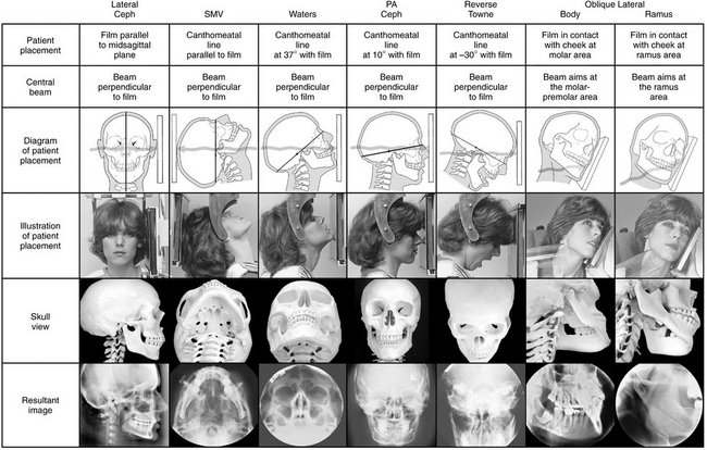
Proper positioning of the x-ray source, patient, and image receptor requires patience, attention to detail, and experience. The main anatomic landmark used in patient positioning during extraoral radiography is the canthomeatal line, which joins the central point of the external auditory canal to the outer canthus of the eye. The canthomeatal line forms approximately a 10-degree angle with the Frankfort plane, the line that connects the superior border of the external auditory canal with the infraorbital rim. The image receptor and patient placement, central beam direction, and resultant image for the lateral, submentovertex, Waters, posteroanterior, reverse-Towne, and mandibular oblique lateral projections are summarized in Table 12-1 and are described in detail in the following sections.
LATERAL SKULL PROJECTION (LATERAL CEPHALOMETRIC PROJECTION)
Of the extraoral radiographs described in this chapter, the lateral cephalometric projection is by far the most commonly used in dentistry. All cephalometric radiographs, including the lateral view, are made with a cephalostat that helps maintain a constant relationship among the skull, the film, and the x-ray beam. Skeletal, dental, and soft tissue anatomic landmarks delineate lines, planes, angles, and distances that are used to generate measurements and to classify patient craniofacial morphologic features. At the beginning of treatment, these measurements are often compared with an established standard; during treatment, the measurements are usually compared with those from previous cephalometric radiographs of the same patient to monitor growth and development as well as treatment.
Image Receptor and Patient Placement
The image receptor is positioned parallel to the patient’s midsagittal plane. The site of interest is placed toward the image receptor to minimize distortion. In cephalometric radiography, the patient is placed with the left side toward the image receptor (U.S. standards), and a wedge filter at the tube head is positioned over the anterior aspect of the beam to absorb some of the radiation and to allow visualization of soft tissues of the face.
Position of the Central X-Ray Beam
The central beam is perpendicular to the midsagittal plane of the patient and the plane of the image receptor and is centered over the external auditory meatus.
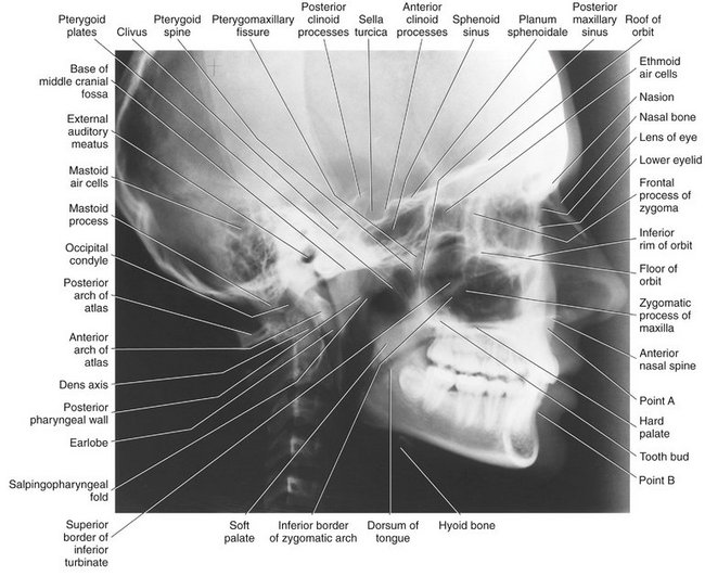
Resultant Image (Fig. 12-1)
Exact superimposition of right and left sides is impossible because structures on the side near the image receptor are magnified less than the same structures on the side far from the image receptor. Bilateral structures close to the midsagittal plane demonstrate less discrepancy in size compared with bilateral structures farther away from the midsagittal plane. Structures close to the midsagittal plane (e.g., the clinoid processes and inferior turbinates) should be nearly superimposed.
There are many cephalometric analyses that are based on a variety of anatomic landmarks. Steiner and Ricketts analyses are two commonly used analyses that use the skeletal, dental, and soft tissue landmarks included in Box 12-1. Precise identification of the various landmarks on the lateral cephalometric radiograph is necessary to generate accurate cephalometric measurements. The landmarks in Box 12-1 are shown in Figure 12-2, A, on a side view of a skull and in Figure 12-2, B, on a 5-mm wide midline section of an orthodontic patient imaged by cone-beam computed tomography. Finally, Figure 12-2, C, depicts the projected landmark position on the lateral cephalogram of an orthodontic patient. Although taken for a specific purpose, a lateral cephalometric radiograph is still a lateral skull film and should be interpreted as such. It is not sufficient to limit the interpretation to the cephalometric analysis.
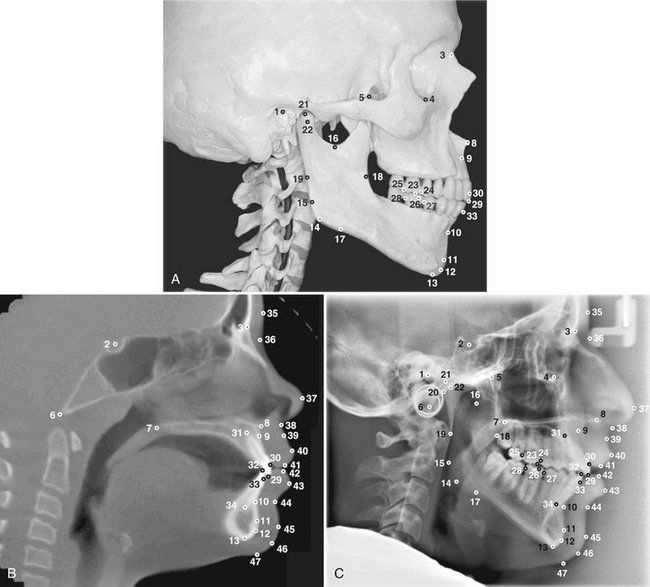
FIG. 12-2 A, Anatomic cephalometric landmarks shown on a side view of the skull. B, Midline anatomic cephalometric landmarks depicted on a 5-mm-wide CBCT (cone-beam computed tomography) scan section of an orthodontic patient. C, Cephalometric landmarks used in Steiner and Ricketts cephalometric analyses.
SUBMENTOVERTEX (BASE) PROJECTION
Image Receptor and Patient Placement
The image receptor is positioned parallel to patient’s transverse plane and perpendicular to the midsagittal and coronal planes. To achieve this, the patient’s neck is extended as far backward as possible, with the canthomeatal line forming a 10-degree angle with the image receptor.
Position of the Central X-Ray Beam
The central beam is perpendicular to the image receptor, directed from below the mandible toward the vertex of the skull (hence the name submentovertex, or SMV), and centered about 2 cm anterior to a line connecting the right and left condyles.
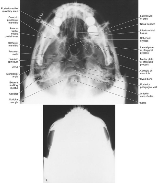
Resultant Image (Fig. 12-3)
The midsagittal plane (represented by an imaginary line extending from the interproximal space of the maxillary central incisors through the nasal septum, to the middle of the anterior arch of the atlas, and to the dens) should divide the skull image in two symmetric halves. The buccal and lingual cortical plates of the mandible should be projected as uniform opaque lines. An underexposed view is required for the evaluation of the zygomatic arches because they will be overexposed or “burned out” on radiographs obtained with normal exposure factors.
WATERS PROJECTION
Image Receptor and Patient Placement
The image receptor is placed in front of the patient and perpendicular to the midsagittal plane. The patient’s head is tilted upward so that the canthomeatal line forms a 37-degree angle with the image receptor. If the patient’s mouth is open, the sphenoid sinus will be seen superimposed over the palate.
Position of the Central X-Ray Beam
The central beam is perpendicular to the image receptor and centered in the area of the maxillary sinuses.
Resultant Image (Fig. 12-4)
The midsagittal plane (represented by an imaginary line extending from the interproximal space of the maxillary central incisors through the nasal septum and the middle of the bridge of the nose) should divide the skull image in two symmetric halves. The petrous ridge of the temporal bone should be projected below the floor of the maxillary sinus.

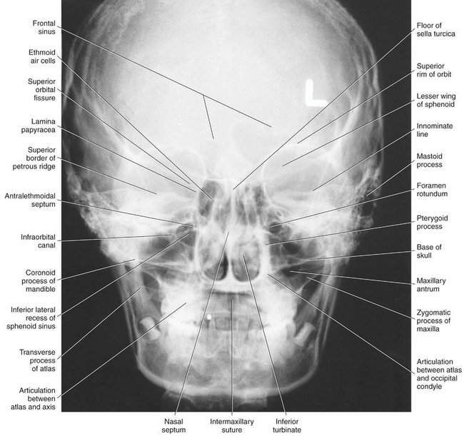
POSTEROANTERIOR SKULL PROJECTION (POSTEROANTERIOR CEPHALOMETRIC PROJECTION)
Image Receptor and Patient Placement
The image receptor is placed in front of the patient, perpendicular to the midsagittal plane and parallel to the coronal plane. The patient is placed so that the canthomeatal line forms a 10-degree angle with the horizontal plane and the Frankfort plane is perpendicular to the image receptor. In the posteroanterior (PA) skull projection, the canthomeatal line is perpendicular to the image receptor.
Position of the Central X-Ray Beam
The central beam is perpendicular to the image receptor, directed from the posterior to the anterior (hence the name posteroanterior, or PA), parallel to patient’s midsagittal plane, and is centered at the level of the bridge of the nose.
Resultant Image (Fig. 12-5)
The midsagittal plane (represented by an imaginary line extending from the interproximal space of the central incisors through the nasal septum and the middle of the bridge of the nose) should divide the skull image into two symmetric halves. The superior border of the petrous ridge should lie in the lower third of the orbit.
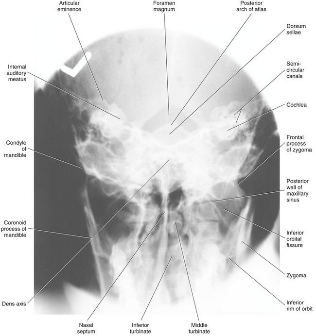
REVERSE-TOWNE PROJECTION (OPEN-MOUTH)
Image Receptor and Patient Placement
The image receptor is placed in front of the patient, perpendicular to the midsagittal and parallel to the coronal plane. The patient’s head is tilted downward so that the canthomeatal line forms a 25- to 30-degree angle with the image receptor. To improve the visualization of the condyles, the patient’s mouth is opened so that the condylar heads are located inferior to the articular eminence. When the clinician requests this image to evaluate the condyles, it is necessary to specify “open-mouth, reverse-Towne” otherwise a standard Towne view of the occiput may result.
Position of the Central X-Ray Beam
The central beam is perpendicular to the image receptor and parallel to patient’s midsagittal plane and it is centered at the level of the condyles.
Resultant Image (Fig. 12-6)
The midsagittal plane (represented by an imaginary line extending from the middle of the foramen magnum and the posterior arch of the atlas through the middle of the bridge of the nose and the nasal septum) should divide the skull image into two symmetric halves. The petrous ridge of the temporal bone should be superimposed at the inferior part of the occipital bone, and the condylar heads should be projected inferior to the articular eminence.
MANDIBULAR OBLIQUE LATERAL PROJECTIONS
Image Receptor and Patient Placement
The image receptor is placed against the patient’s cheek on the side of interest and centered in the molar-premolar area. The lower border of the cassette is parallel and at least 2 cm below the inferior border of the mandible. The head is tilted toward the side being examined, and the mandible is protruded.
Position of the Central X-Ray Beam
The central beam is directed toward the molar-premolar region from a point 2 cm below the angle of the opposite side of the mandible.
Resultant Image (Fig. 12-7)
A clear image of the teeth, the alveolar ridge, and the body of the mandible should be obtained. If significant distortion is present, the head was tilted excessively. If the contralateral side of the mandible is superimposed over the area of interest, the head was not tilted sufficiently.
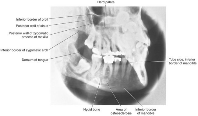
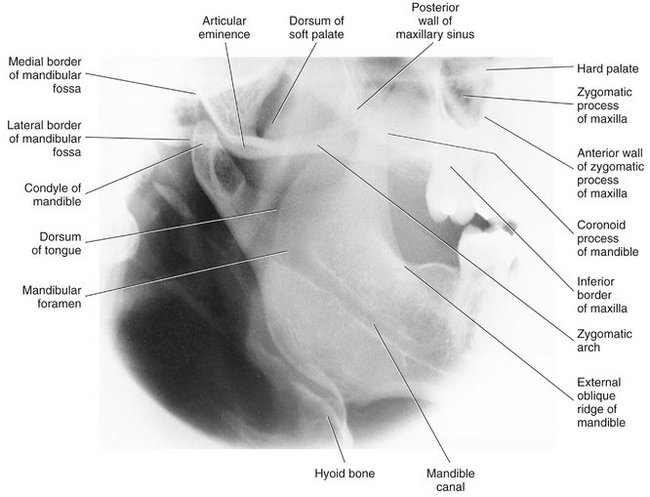
Image Receptor and Patient Placement
The image receptor is placed over the ramus and far enough posteriorly to include the condyle. The lower border of the cassette is parallel and at least 2 cm below the inferior border of the mandible. The head is tilted toward the side being examined so that the condyle of the area of interest and the contralateral angle of the mandible form a horizontal line. The mandible is protruded.
Position of the Central X-Ray Beam
The central beam is directed toward the center of the imaged ramus, from 2 cm below the inferior border of the opposite side of the mandible at the area of the first molar.
Resultant Image (Fig. 12-8)
A clear image of the third molar–retromolar area, angle of the mandible, ramus, and condyle head should be obtained. If significant distortion is present, the head was tilted excessively. If the contralateral side of the mandible is superimposed over the area of interest, the head was not tilted sufficiently.
Evaluating the Image
Extraoral images should first be evaluated for overall quality. Proper exposure and processing will result in an image with good contrast and density. Proper patient positioning prevents unwanted superimpositions and distortions and facilitates identification of anatomic landmarks. Interpreting poor-quality images can lead to diagnostic errors and subsequent treatment errors.
The first step in the interpretation of radiographic images is the identification of anatomy. A thorough knowledge of normal radiographic anatomy and the appearance of normal variants is critical for the identification of pathology. Abnormalities cause disruptions of normal anatomy. Detecting the altered anatomy precedes classifying the type of change and developing a differential diagnosis. What is not detected cannot be interpreted. Figures 12-1 through 12-8 present the major anatomic landmarks that can be identified in the various extraoral projections.
Interpretation of extraoral radiographs should be thorough, careful, and meticulous. Images should be interpreted in a room with reduced ambient light, and peripheral light from the viewbox or monitor should be masked. A systematic, methodical approach should be used for the visual exploration or interrogation of the diagnostic image. A method for the visual interrogation of extraoral projections is presented below. This method is not the only approach to examining radiographic images. Any technique that reliably ensures that the entire image will be examined is equally appropriate.
LATERAL PROJECTION (FIG. 12-9)
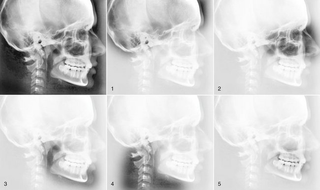
FIG. 12-9 Interrogating the lateral cephalometric projection. The radiograph in the upper left demonstrates the whole image. Subsequent radiographs correspond to the steps of interrogation.
Step 1 Evaluate the base of the skull and calvarium. Identify the mastoid air cells, clivus, clinoid processes, sella turcica, sphenoid sinuses, and roof of the orbit. In the calvarium, assess vessel grooves, sutures, and diploic space. Look for intracranial calcifications.
Step 2 Evaluate the upper and middle face. Identify the orbits, sinuses (frontal, ethmoid, and maxillary), pterygomaxillary fissures, pterygoid plates, zygomatic processes of the maxilla, anterior nasal spine, and hard palate (floor of the nose). Evaluate the soft tissues of the upper and middle face, nasal cavity (turbinates), soft palate, and dorsum of tongue.
Step 3 Evaluate the lower face. Follow the outline of the mandible, starting from the condylar and coronoid processes, to the rami, angles, and bodies, and finally to the anterior mandible. Evaluate the soft tissue of the lower face.
Step 4 Evaluate the cervical spine, airway, and area of the neck. Identify each individual vertebra, confirm that the skull-C1 and C1-C2 articulations are normal, and assess the general alignment of the vertebrae. Assess soft tissues of the neck, hyoid bone, and airway.
SMV PROJECTION (FIG. 12-10)
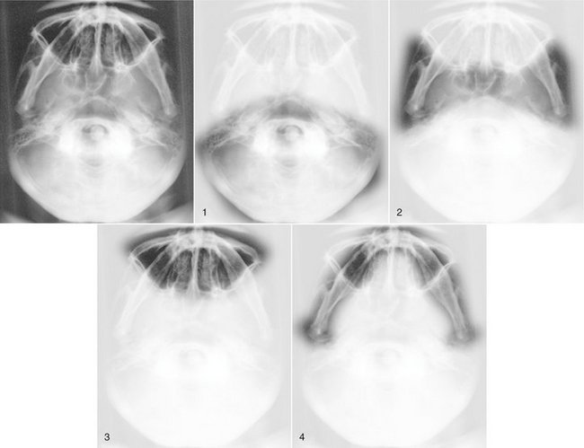
FIG. 12-10 Interrogating the submentovertex projection. The radiograph in the upper left demonstrates the whole image. Subsequent radiographs correspond to the steps of interrogation.
Step 1 Evaluate the calvarium and posterior cranial fossa. Assess the foramen magnum, atlas, dens, and occipital condyles. Identify the petrous ridge of the right and left temporal bones, the external auditory canals, and the mastoid air cells. In this and all subsequent steps, compare the right and left sides and look for symmetry.
Step 2 Evaluate the middle cranial fossa. Identify the foramina ovale and spinosum. Assess the clivus and sphenoid sinuses.
Step 3 Evaluate the upper and middle face. Assess the nasal cavity, nasal septum, maxillary and ethmoid sinuses, and orbits. Assess both the bony borders and antra or contents of these structures.
Step 4 Evaluate the mandible. Follow the outline from the right condylar head, coronoid process, ramus, angle, and body through the anterior mandible to the left body, angle, ramus, coronoid process, and condyle.
WATERS PROJECTION (FIG. 12-11)
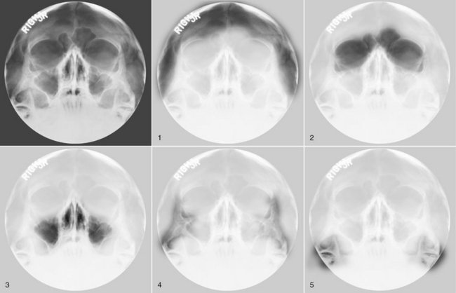
FIG. 12-11 Interrogating the Waters projection. The radiograph in the upper left demonstrates the whole image. Subsequent radiographs correspond to the steps of interrogation.
Step 1 Evaluate the calvarium and sutures, starting in the left temporal area over the supraorbital ridges to the right temporal area. Look for intracranial calcifications. In this and all subsequent steps, compare the right and left sides and look for symmetry.
Step 2 Evaluate the orbits and the frontal sinuses. Identify the supraorbital and infraorbital rim, the inferior orbital foramen, the floor of the orbit, the zygomaticofrontal sutures, and the innominate line of the infratemporal fossa crossing on the lateral aspect of each orbit.
Step 3 Evaluate the maxillary sinuses and nasal cavity. Identify the superior, medial, and lateral walls and the floor of the maxillary sinuses; the nasal septum; and the floor and lateral walls of the nasal cavity. Try to identify the foramen rotundum projected toward the mesial wall of the sinus.
Step 4 Evaluate the zygomatic arches. Identify the frontal, maxillary, and temporal processes of the zygoma and the zygomaticofrontal suture. Confirm continuity of outlines and symmetry with the contralateral side.
Step 5 Evaluate the condylar and coronoid processes of the mandible. This is one of the best PA views of the coronoid process.
POSTEROANTERIOR PROJECTION (FIG. 12-12)
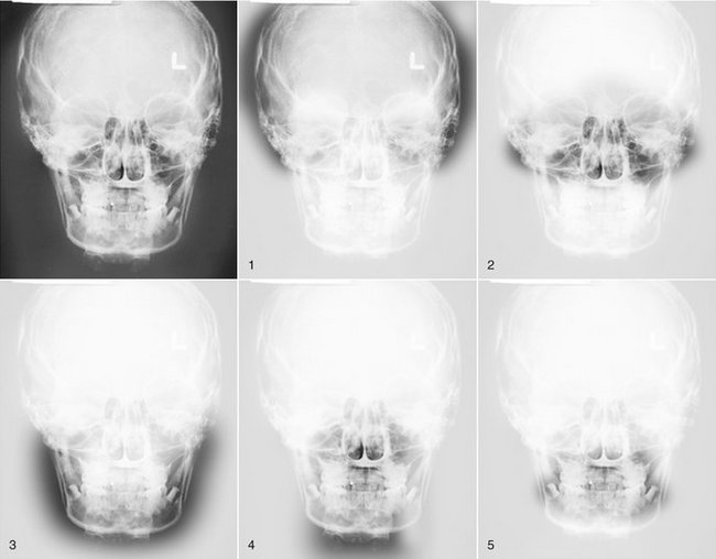
FIG. 12-12 Interrogating the PA cephalometric projection. The radiograph in the upper left demonstrates the whole image. Subsequent radiographs correspond to the steps of interrogation.
Step 1 Evaluate the calvarium, sutures, and diploic space starting in the area of the left external auditory meatus (EAM), over the top of the calvarium, to the right EAM. Look for intracranial calcifications. Identify the mastoid air cells and petrous ridge of the right and left temporal bones. In this and all subsequent steps, compare the right and left sides and look for symmetry.
Step 2 Evaluate the upper and middle face. Identify the orbits, sinuses (frontal, ethmoid, and maxillary), and zygomatic processes of the maxilla. Assess the nasal cavity, middle and inferior turbinates, nasal septum, and hard palate.
Step 3 Evaluate the lower face. Follow the outline of the mandible starting from the right condylar and coronoid processes, ramus, angle, and body through the anterior mandible to the left body, angle, ramus, coronoid process, and condyle.
Step 4 Evaluate the cervical spine. Identify the dens, the superior border of C2, and the inferior border of C1.
REVERSE-TOWNE PROJECTION (FIG. 12-13)
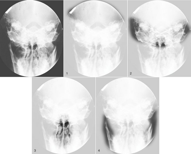
FIG. 12-13 Interrogating the reverse-Towne projection. The radiograph in the upper left demonstrates the whole image. Subsequent radiographs correspond to the steps of interrogation.
Step 1 Evaluate the calvarium and look for intracranial calcifications. Identify the foramen magnum and the posterior arch of the atlas. In this and all subsequent steps, compare the right and left sides and look for symmetry.
Step 2 Evaluate the middle cranial fossa, petrous ridges, and mastoid air cells. The anatomy in this area is difficult to discern. Look for displacement, interruption of outlines, radiolucencies, and loss of symmetry. Identify the odontoid process (dens) of the axis (C2) in the midline.
Step 3 Evaluate the nasal cavity. Identify the outline of the nasal cavity, the nasal septum, and the inferior and middle turbinates.
Step 4 Evaluate the condylar and coronoid process. In the open-mouth projection, the condylar head, including its superior surface and condylar neck, should be identified.
Selection Criteria
Although this section appears toward the end of this chapter, in practice, selecting the appropriate extraoral radiographic examination is the first step in obtaining and interpreting a radiograph.
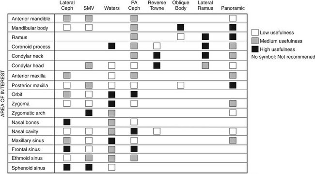
Extraoral radiographs are used to examine areas not fully covered by intraoral films or to evaluate the cranium, face (including the maxilla and mandible), or cervical spine for diseases, trauma, or abnormalities. Before an extraoral radiograph is obtained, it is essential to evaluate the patient’s complaints and clinical signs in detail. The clinician must first decide which anatomic structures need to be evaluated and then select the appropriate projection(s). Usually, at least two radiographs taken at right angles to each another are obtained for spatial localization of pathologic conditions. Figure 12-14 summarizes the use of extraoral radiographs for the evaluation of various anatomic structures. Although panoramic radiography is the subject of another chapter, it is included in Figure 12-14 for comparison.
Ballinger, PW, Frank, ED. ed 10. Merrill’s atlas of radiographic positions and radiologic procedures. St. Louis: Mosby; 2003;vol 2.
Kantor, ML, Norton, LA. Normal radiographic anatomy and common anomalies seen in cephalometric films. Am J Orthod Dentofac Orthop. 1987;91:414–426.
Keats, TE, Anderson, MW. Atlas of normal roentgen variants that may simulate disease, ed 7. St. Louis: Mosby; 2001.
Miyashita, K. Contemporary cephalometric radiography. Tokyo: Quintessence; 1996.
Shapiro, R. Radiology of the normal skull. Chicago: Year Book Medical; 1981.
Swischuk, LE. Imaging of the cervical spine in children. New York: Springer-Verlag; 2002.