Chapter 11 Bitewing radiography
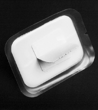
Bitewing radiographs take their name from the original technique which required the patient to bite on a small wing attached to an intraoral film packet (see Fig. 11.1). Modern techniques use holders, as shown later, which have eliminated the need for the wing (now termed a tab), and digital image receptors (solid-state or phosphor plate) can be used instead of film, but the terminology and clinical indications have remained the same. An individual image is designed to show the crowns of the premolar and molar teeth on one side of the jaws.
IDEAL TECHNIQUE REQUIREMENTS
• An appropriate image receptor holder with beam aiming device should be used and is recommended in the UK in the 2001 Guidance Notes for Dental Practitioners on the Safe Use of X-ray Equipment.
• The image receptor should be positioned centrally within the holder with the upper and lower edges of the image receptor parallel to the bite-platform.
• The image receptor should be positioned with its long axis horizontally for a horizontal bitewing or vertically for a vertical bitewing (Fig. 11.2).
• The posterior teeth and the image receptor should be in contact or as close together as possible.
• The posterior teeth and the image receptor should be parallel — the shape of the dental arch may necessitate two separate image receptor positions to achieve this requirement for both the premolar and the molar teeth (Fig. 11.3).
• The beam aiming device should ensure that in the horizontal plane, the X-ray tubehead is aimed so that the beam meets the teeth and the image receptor at right angles, and passes directly through all the contact areas (Fig. 11.3).
• The beam aiming device should ensure that in the vertical plane, the X-ray tubehead is aimed downwards (approximately 5°–8° to the horizontal) to compensate for the upwardly rising curve of Monson (Fig. 11.4).
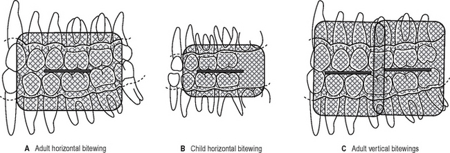
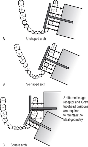
Fig. 11.3 Diagrams showing the ideal image receptor and X-ray tubehead positions (determined by the beam aiming device) for different arch shapes.
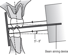
Fig. 11.4 Diagram showing the ideal image receptor position and the approximate 5°—8° downward vertical angulation of the X-ray beam (determined by the beam aiming device) compensating for the curve of Monson.
It is sometimes not possible to use an image receptor holder (with beam aiming device) and achieve these ideal technical requirements — particularly in children. Clinicians therefore still need to be aware of the original technique of using a tab attached to the film packet or phosphor plate and aligning the X-ray tubehead by eye.
POSITIONING TECHNIQUES
Using image receptor holders with beam aiming devices
Several image receptor holders with different beam aiming devices have been produced for use with film packets or digital phosphor plates and with digital solid state sensors, held either horizontally or vertically. A selection of different holders is shown in Figure 11.5. As in periapical radiography, the choice of holder is a matter of personal preference and dependent upon the type of image receptors being employed. The various holders vary in cost and design but essentially consist of the same three basic components that make up periapical holders (see Ch. 10), namely:
• A mechanism for holding the image receptor parallel to the teeth
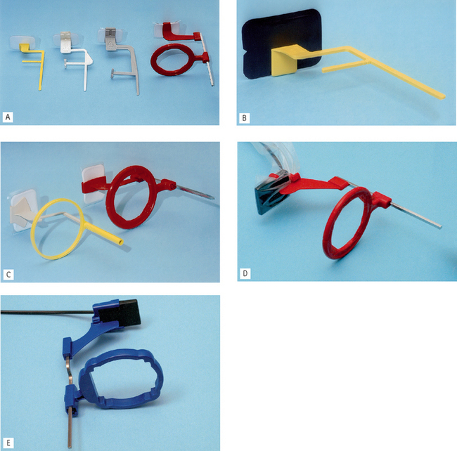
Fig. 11.5 Bitewing image receptor holders with beam aiming devices. A A selection of horizontal bitewing holders set up using a film packet as the image receptor — note the red colour coding for the Rinn XCP System. B The Hawe-Neos Kwikbite horizontal holder set up using a digital phosphor plate. C Vertical bitewing holders — the red Rinn XCP holder and the yellow Hawe-Neos Parobite holder set up using film packets. D The red Rinn XCP-DS horizontal bitewing solid-state digital sensor holder. E The Planmeca horizontal bitewing holder designed specifically for use with their dixi2 solid-state digital sensors.
The radiographic technique can be summarized as follows:
1. The desired holder is selected together with an appropriate sized image receptor — typically a 31 × 41 mm film packet or phosphor plate or the equivalent sized solid-state sensor.
2. The patient is positioned with the head supported and with the occlusal plane horizontal.
3. The holder is inserted carefully into the lingual sulcus opposite the posterior teeth.
4. The anterior edge of the image receptor should be positioned opposite the distal aspect of the lower canine — in this position the image receptor extends usually just beyond the mesial aspect of the lower third molar (see Fig. 11.6).
5. The patient is asked to close the teeth firmly together onto the bite platform. (Note: Extra care needs to be taken of solid state sensor cables.)
6. The X-ray tubehead is aligned accurately using the beam aiming device to achieve optimal horizontal and vertical angulations (see Fig. 11.7).
8. If required, the procedure is repeated for the premolar teeth with a new image receptor and X-ray tubehead position.
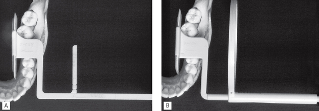
Fig. 11.6 A Position of the simple Hawe-Neos Kwikbite holder in relation to the teeth. B Position of the Hawe-Neos Kwikbite holder (with circular beam-aiming device) in relation to the teeth.
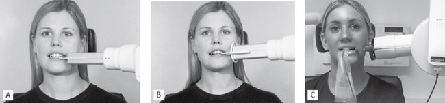
Fig. 11.7 Clinical positioning for A Simple Hawe-Neos Kwikbite holder using a film packet or digital phosphor plate, B Hawe-Neos holder (with circular beam aiming device) using a film packet or digital phosphor plate and C Planmeca holder using a solid-state digital sensor.
Advantages
• Relatively simple and straightforward.
• Image receptor is held firmly in position and cannot be displaced by the tongue.
• Position of X-ray tubehead is determined by the beaming device so assisting the operator in ensuring that the X-ray beam is always at right angles to the image receptor.
• Avoids coning off or cone cutting of the anterior part of the image receptor.
Disadvantages
• Position of the holder in the mouth is operator-dependent, therefore images are not 100% reproducible, so still not ideal for monitoring progression of caries.
• Positioning of the film holder and image receptor can be uncomfortable for the patient particularly when using solid-state digital sensors.
Using a tab attached to the image receptor
The traditional bitewing technique is particularly suitable when using film packets or digital phosphor plates as the image receptor. Although, as explained below, the technique is very operator- dependent and not recommended for adults, it is still widely used for children.
The radiographic technique can be summarized as follows:
1. The appropriate sized barrier-wrapped film packet or phosphor plate is selected and the tab attached, orientated appropriately for horizontal or vertical projections, as shown in Figure 11.8A:
2. The patient is positioned with the head supported and with the occlusal plane horizontal.
3. The shape of the dental arch and the number of films required are assessed.
4. The operator holds the tab between thumb and forefinger and inserts the image receptor into the lingual sulcus opposite the posterior teeth.
5. The anterior edge of the image receptor should again be positioned opposite the distal aspect of the lower canine — in this position, the posterior edge of the film packet extends usually just beyond the mesial aspect of the lower third molar (see Fig. 11.8B).
6. The tab is placed on to the occlusal surfaces of the lower teeth.
7. The patient is asked to close the teeth firmly together on the tab.
8. As the patient closes the teeth, the operator pulls the tab firmly between the teeth to ensure that the image receptor and teeth are in contact.
9. The operator releases the tab.
10. The operator assesses the horizontal and vertical angulations and positions the X-ray tubehead so that the X-ray beam is aimed directly through the contact areas, at right angles to the teeth and the image receptor, with an approximately 5°–8° downward vertical angulation (see Fig. 11.9A and B).
12. If required, the procedure is repeated for the premolar teeth with a new image receptor and X-ray tubehead position.
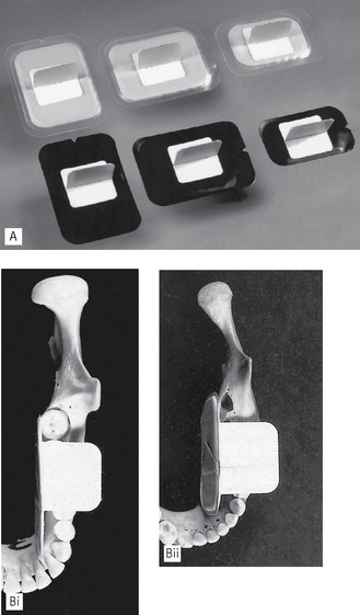
Fig. 11.8 A Film packets and phosphor plates with tabs attached suitable for adult vertical bitewings, adult horizontal bitewings and child’s horizontal bitewings. B The ideal bitewing and film packet position in relation to the teeth for (i) an adult and (ii) a child.
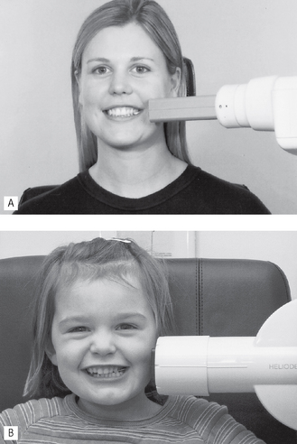
Fig. 11.9 A Adult patient and X-ray tubehead positioning for a left bitewing. B Positioning for a child.
Note: When positioning the X-ray tubehead, after the patient has closed the mouth, the film can no longer be seen. To ensure that the anterior part of the image receptor is exposed and to avoid coning off and cone cutting, a simple guide to remember is that the front edge of the open-ended spacer cone should be positioned adjacent to the corner of the mouth.
Disadvantages
• Arbitrary, operator-dependent assessment of horizontal and vertical angulations of the X-ray tubehead.
• Images not accurately reproducible, so not ideal for monitoring the progression of caries.
• Coning off or cone cutting of anterior part of image receptor is common,
RESULTANT RADIOGRAPHS
Whichever radiographic technique is used, the resultant radiographic images and the anatomical structures they show are very similar — it is their accuracy that varies. Examples are shown in Figure 11.10-11.12.
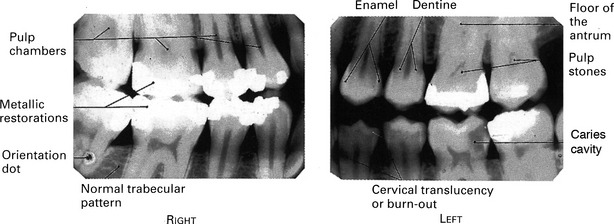
Fig. 11.10 Examples of typical RIGHT and LEFT horizontal adult bitewing radiographs, suitable for the assessment of caries and restorations, with the main radiographic features indicated.
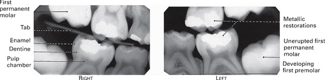
Fig. 11.11 Examples of typical RIGHT and LEFT bitewing radiographs of a child with the main radiographic features indicated.
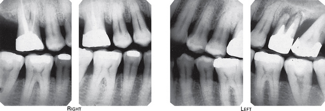
Fig. 11.12 Example of typical RIGHT and LEFT vertical adult bitewing radiographs. Note that two films are used on each side to image both the premolars and molars.
Assessment of image quality
As described in Chapter 10, image quality assessment essentially involves three separate stages, namely:
• Comparison of the image against ideal quality criteria
• Subjective rating of image quality using published standards
• Detailed assessment of rejected films to determine the source of error.
Ideal quality criteria
Irrespective of the type of image receptor being used, typical quality criteria for a bitewing radiograph should include:
• The image should have acceptable definition with no distortion or blurring.
• The image should include from the mesial surface of the first premolar to the distal surface of the second molar — if the third molars are erupted then the 7/8 contact should be included.
• The occlusal plane/bite-platform should be in the middle of the image so that the crowns and coronal parts of the roots of the maxillary teeth are shown in the upper half of the image and the crowns and coronal parts of the roots of the mandibular teeth are shown in the lower half of the image, and the buccal and lingual cusps should be superimposed.
• The maxillary and mandibular alveolar crests should be shown.
• There should be no overlap of the approximal surfaces of the teeth.
• The desired density and contrast for film-captured images will depend on the clinical reasons for taking the radiograph, e.g.
• The image should be free of coning off or cone-cutting and other film handling errors.
• The image should be comparable with previous bitewing images both geometrically and in density and contrast.
Subjective rating of image quality
The simple three-point subjective rating scale published in the 2001 Guidance Notes was introduced in Chapter 10 and is discussed in detail, together with the errors associated with exposure factors and chemical processing, in Chapter 18. A summary is shown again in Table 11.1. Patient preparation and positioning errors in bitewing radiography are described below.
Table 11.1 Subjective quality rating criteria for film-captured images published in the 2001 Guidance Notes for Dental Practitioners on the Safe Use of X-ray Equipment
| Rating | Quality | Basis |
|---|---|---|
| 1 | Excellent | No errors of patient preparation, exposure, positioning, processing or film handling |
| 2 | Diagnostically acceptable | Some errors of patient preparation, exposure, positioning, processing or film handling, but which do not detract from the diagnostic utility of the radiograph |
| 3 | Unacceptable | Errors of patient preparation, exposure, positioning, processing or film handling, which render the radiograph diagnostically unacceptable |
Assessment of rejected films and determination of errors
Patient preparation and positioning (radiographic technique) errors (Fig. 11.13)
• Positioning the image receptor too far posteriorly in the mouth thereby failing to image the premolar teeth.
• Failure to insert image receptor correctly into the lingual sulcus between the tongue and posterior teeth allowing the tongue to displace the film.
• Failure to align the X-ray tubehead correctly in the horizontal plane, either
• Failure to align the X-ray tubehead correctly in the vertical plane thereby not superimposing the buccal and lingual cusps.
• Failure to set correct exposure settings.
• Failure to instruct the patient to remain still during the exposure with subsequent movement resulting in blurring.
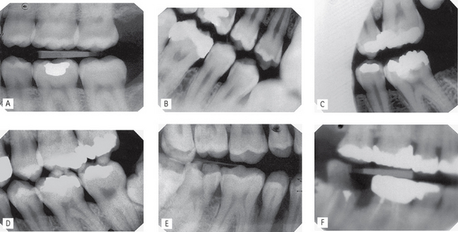
Fig. 11.13 A selection of bitewings showing patient preparation and positioning errors.
A Image receptor positioned too far posteriorly — the edentulous area distal to the lower second is imaged but not the premolar teeth.
B Image receptor displaced by tongue — occlusal plane not horizontal.
C Failure to align the X-ray tubehead correctly in the horizontal plane — coning off of the anterior part of the image.
D Failure to align the X-ray tubehead correctly in the horizontal plane — overlapping of the contact areas.
E Failure to align the X-ray tubehead correctly in the vertical plane — buccal and lingual cusps not superimposed and distortion of the teeth.
F Failure to instruct the patient to remain still — image blurred as a result of movement.
Note: Many of these positioning errors can be avoided by using image receptor holders with beam-aiming devices but are relatively common when not using a holder and aligning and positioning the X-ray tubehead without a guide.