Chapter 18 The quality of radiographic images and quality assurance
INTRODUCTION
The factors that can affect the quality of radiographic images depends on:
The effects of poor radiographic technique are the same whatever type of image receptor is used. These technique errors have already been covered in detail in relation to the three main projections used in dentistry, namely: periapicals (Ch. 10), bitewings (Ch. 11) and panoramic radiographs (Ch. 17).
The creation of the visual digital image was described in Chapter 7, together with how computer software can be used to alter and manipulate the image with regards to contrast, brightness (degree of blackening), magnification, inversion, enhancement and pseudocolourization.
Creation of the black/white/grey image on film using chemical processing was also described in Chapter 7. This film-captured image can however be affected by many other factors. This chapter therefore is designed for revision, bringing together and summarizing from earlier chapters all these various factors. It also includes a quick reference section as an aid to fault-finding of film-captured images. Various film faults are illustrated together with their possible causes. This is followed by a section on quality assurance (QA) and suggested quality control measures.
IMAGE QUALITY
As mentioned in Chapter 1, image quality and the amount of detail shown on a radiographic film depends on several factors including:
Contrast
Radiographic contrast, i.e. the final visual difference between the various black, white and grey shadows depends on:
Subject contrast
This is the difference caused by different degrees of attenuation as the X-ray beam is transmitted through different parts of the patient’s tissues. It depends upon:
Film contrast
This is an inherent property of the film itself (see Ch. 6). It determines how the film will respond to the different exposures it receives after the X-ray beam has passed through the patient. Film contrast depends upon four factors:
Image geometry
As mentioned and illustrated in Chapter 1, the geometric accuracy of any image depends upon the position of the X-ray beam, object and image receptor (film or digital) satisfying certain basic geometrical requirements:
Characteristics of the X-ray beam
The ideal X-ray beam used for imaging should be:
• Sufficiently penetrating to pass through the patient, to a varying degree, and react with the film emulsion to produce good contrast between the various black, white and grey shadows (see earlier)
• Parallel, i.e. non-diverging, to prevent magnification of the image (see Ch. 5)
• Produced from a point source to reduce blurring of the image margins and the penumbra effect (see Ch. 5).
Image sharpness and resolution
Sharpness is defined as the ability of the X-ray film to define an edge. The main causes of loss of edge definition include:
• Geometric unsharpness including the penumbra effect (see above)
• Motion unsharpness, caused by the patient moving during the exposure
• Absorption unsharpness — caused by variation in object shape, e.g. cervical burn-out at the neck of a tooth (see Ch. 21)
• Screen unsharpness, caused by the diffusion and spread of the light emitted from intensifying screens (see Ch. 6)
• Poor resolution. Resolution, or resolving power of the film, is a measure of the film’s ability to differentiate between different structures and record separate images of small objects placed very close together, and is determined mainly by characteristics of the film including:
PRACTICAL FACTORS INFLUENCING IMAGE QUALITY
In practical terms, the various factors that can influence overall image quality can be divided into factors related to:
As a result of all these variables, film faults and alterations in image quality are inevitable. However, since the diagnostic yield from radiography is related directly to the quality of the image, regular checks and monitoring of these variables are essential to achieve and maintain good quality radiographs. It is these checks which form the basis of quality assurance (QA) programmes.
Clinicians using film need to be able to recognize the cause of the various film faults so that appropriate corrective action can be taken.
TYPICAL FILM FAULTS
Examples of typical film faults are shown below and summarized later in Table 18.1.
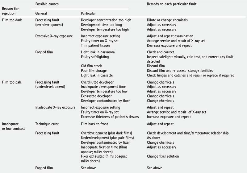
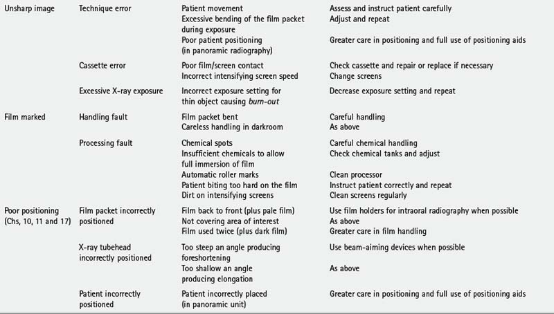
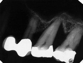
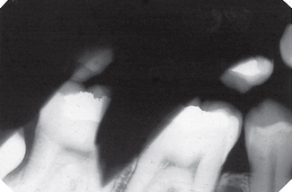
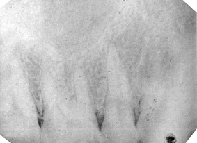
Image unsharp and blurred (Fig. 18.4)
Possible causes
• Movement of the patient during the exposure (see also Chs 10, 11 and 17)
• Excessive bending of the film packet during the exposure (see also Ch. 10)
• Poor film/screen contact within a cassette
• Film type — image definition is poorer with indirect-action film than with direct-action film
• Speed of intensifying screens — fast screens result in loss of detail
• Overexposure — causing burn-out of the edges of a thin object
• Poor positioning in panoramic radiography (see Ch. 17).
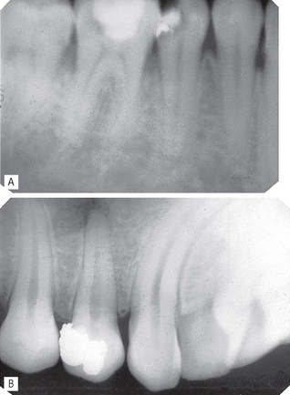
Film marked (Fig. 18.5)
Possible causes
• Film packet bent by the operator
• Careless handling of the film in the darkroom resulting in marks caused by:
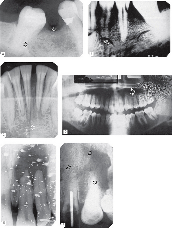
Fig. 18.5 Examples of marked films.
A Finger print impression in the emulsion (arrowed).
B Finger nail marks (arrowed).
C Sharply bent film (arrowed) damaging the emulsion.
D Discharge of static electricity (arrowed).
E Fixer splashes on the emulsion before the film was placed in the developer.
F Marks (arrowed) caused by residual emulsion remaining following inadequate fixation (these are usually brown).
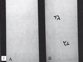
PATIENT PREPARATION AND POSITIONING (RADIOGRAPHIC TECHNIQUE) ERRORS (FIG. 18.6)
These errors can happen whatever image receptor is being used and were described in detail and illustrated in Chapters 10, 11 and 17. They are summarized below and can be divided into intraoral and panoramic technique errors.
Fig. 18.6 Two examples of positioning (radiographic technique) errors. A Intraoral – coning off or cone cutting – X-ray tubehead incorrectly positioned, anterior part of image receptor not exposed. B Panoramic — patient too far away from the image receptor — incisor teeth magnified (anteroposterior error) and patient rotated to the LEFT, left molars narrowed, right molars widened (horizontal error).
Intraoral technique errors
• Failure to position the image receptor correctly to capture the area of interest
• Failure to position the image receptor correctly causing it to bend (if flexible) creating geometrical distortion
• Failure to orientate the image receptor correctly and using it back-to front
• Failure to align the X-ray tubehead correctly in the horizontal plane causing:
• Failure to align the X-ray tubehead correctly in the vertical plane causing:
• Failure to instruct the patient to remain still during the exposure with subsequent movement resulting in blurring
• Failure to set correct exposure settings (image too dark or too pale — see earlier)
Panoramic technique errors
• Failure to remove orthondontic appliances
• Failure to remove spectacles
• Inappropriate use of a protective lead apron
• Failure to ensure the spine is straight
• Failure to ensure the incisors are biting on the bite-peg (anteroposterior error)
• Failure to use the light beam markers to ensure mid-sagittal plane is vertical and Frankfort plane is horizontal (horizontal and vertical errors)
• Failure to instruct the patient to press the tongue against the roof of the mouth
• Failure to instruct the patient to remain still throughout the exposure cycle
• Failure to set machine height adjustment correctly
• Failure to set correct exposure settings (image too dark or too pale — see earlier)
QUALITY ASSURANCE IN DENTAL RADIOLOGY
The World Health Organization has defined radiographic quality assurance (QA) programmes as ‘… an organised effort by the staff operating a facility to ensure that the diagnostic images produced by the facility are of sufficiently high quality so that they consistently provide adequate diagnostic information at the lowest possible cost and with the least possible exposure of the patient to radiation’.
Quality control measures are therefore as essential in a general dental practice facility, as they are in a specialized radiography department. This importance of quality is acknowledged in the UK in the Ionising Radiations Regulations 1999 (see Ch. 8) which make quality assurance in dental radiography a mandatory requirement. A section in the 2001 Guidance Notes for Dental Practitioners on the Safe Use of X-ray Equipment is devoted to quality assurance and should be regarded as essential reading. This chapter is based broadly on the recommendations in the 2001 Guidance Notes.
Terminology
The main terms in quality procedures include:
• Quality control — the specific measures for ensuring and verifying the quality of the radiographs produced.
• Quality assurance — the arrangements to ensure that the quality control procedures are effective and that they lead to relevant change and improvement.
• Quality audit — the process of external reassurance and assessment that quality control and quality assurance mechanisms are satisfactory and that they work effectively.
Quality assurance programme
A basic principle of quality assurance is that, within the overall QA programme, all necessary procedures should be laid down in writing and in particular:
• Implementation should be the responsibility of a named person
• Frequency of operations should be defined
• The content of the essential supporting records should be defined and the frequency for the formal checking of such records.
As stated in the 2001 Guidance Notes and implied by the WHO definition, a well-designed QA programme should be comprehensive but inexpensive to operate and maintain. The standards should be well researched but once laid down would be expected to require only infrequent verification or modification. The procedures should amount to little more than ‘written down common sense’. The aims of these programmes, whether using film-based or digital radiography, can be summarized as follows:
Quality control procedures for film-based radiography
The essential quality control procedures relate to:
• Image quality and film reject analysis
• Patient dose and X-ray equipment
Image quality and film reject analysis
Image quality assessment is an important test of the entire QA programme. Hence the need for clinicians to be aware of all the various factors, outlined earlier, that affect image quality and to monitor it on a regular basis. This assessment should include:
• A day-to-day comparison of the quality of every radiograph to a high standard reference film positioned permanently on the viewing screen and an investigation of any significant deterioration in quality.
• A formal analysis of film quality, either retrospective or prospective, approximately every six months. The 2001 Guidance Notes recommended the simple three-point subjective rating scale shown in Table 18.2, and shown previously in Chapters 10, 11 and 17, be used for film-based intra-oral and extra-oral radiography.
• Based on these quality ratings, performance targets can be set. Suitable targets recommended in the Guidance Notes are shown in Table 18.3 with the advice that practices should aim to achieve these targets within three years of implementing the QA programme. The ‘interim targets’ should be regarded as the minimum achievable standard in the shorter term.
• Analysis of all unacceptable films given a rating of 3 sometimes referred to as film reject analysis (see below).
Table 18.2 Subjective quality rating criteria for film-captured images published in 2001 Guidance Notes for Dental Practitioners on the Safe Use of X-ray Equipment
| Rating | Quality | Basis |
|---|---|---|
| 1 | Excellent | No errors of patient preparation, exposure, positioning, processing or film handling |
| 2 | Diagnostically acceptable | Some errors of patient preparation, exposure, positioning, processing or film handling, but which do not detract from the diagnostic utility of the radiograph |
| 3 | Unacceptable | Errors of patient preparation, exposure, positioning, processing or film handling, which render the radiograph diagnostically unacceptable |
Table 18.3 Minimum and interim targets for radiographic quality from the 2001 Guidance Notes
| Percentage of radiographs taken | ||
|---|---|---|
| Rating | Target | Interim target |
| 1 | Not less than 70% | Not less than 50% |
| 2 | Not greater than 20% | Not less than 40% |
| 3 | Not greater than 10% | Not greater than 10% |
Film reject analysis
This is a simple method of identifying all film faults and sources of error and amounts to a register of reject radiographs. To do this, it is necessary to collect all rejected (grade 3) radiographs and record:
• Nature of the film fault/error, as shown earlier, e.g.:
• Known or suspected cause of the error or fault and corrective action taken (see Table 18.1)
• Number of repeat radiographs (if taken)
• Total number of radiographs taken during the same time period. This allows the percentage of faulty films to be calculated.
Regular review of film reject analysis records is an invaluable aid for identifying a range of problems, including a need for equipment maintenance, additional staff training as well as processing faults that could otherwise cause unnecessary radiation exposure of patients and staff.
Patient dose and X-ray equipment
One of the aims of QA stated earlier is to ensure that radiation doses are kept as low as reasonably practicable. It is therefore necessary to measure patient doses on a regular basis and compare them against national diagnostic reference levels. To achieve this, X-ray equipment must comply with current recommendations, as described in Chapter 8. These include:
• The initial critical examination and report — carried out by the installer
• The acceptance test — carried out by the radiation protection adviser before equipment is brought into clinical use and includes measurement of patient dose
• A re-examination report following any relocation, repair or modification of equipment that may have radiation protection implications
• Day-to-day checks of important features that could affect radiation protection including:
• Written records and an equipment log should be maintained and include:
• The Ionizing Radiation (Medical Exposure) Regulations 2000 require that an up-to-date inventory of each item of X-ray equipment is maintained, and available, at each practice and contains:
• Compliance with the recommendations in Ch. 9 of Recommended standards for the routine performance testing of diagnostic X-ray imaging systems, Report 91 of the Institute of Physics and Engineering in Medicine (IPEM) published in 2005.
Darkroom, image receptors and processing
Darkroom
The QA programme should include instructions on all the regular checks that should be made, and how frequently, with all results recorded in a log. Important areas include:
• General cleanliness (daily), but particularly of work surfaces and film hangers (if used).
• Light-tightness (yearly), by standing in the darkroom in total darkness with the door closed and safelights switched off and visually inspecting for light leakage
• Safelights (yearly), to ensure that these do not cause fogging of films. Checks are required on:
A simulated result is shown in Figure 18.7. Fogging (blackening) of the film owing to the safelight will then be obvious when compared to the clear area protected by the coin. The part of the film adjacent to the first coin will have been exposed to the safelight for the longest time and will be the darkest. In practice, the normal film-handling time under the safelight can be measured and the effect of safelight fogging established.
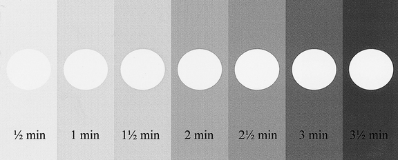
Fig. 18.7 A simulated coin test result. The film, with seven coins on it, has been gradually uncovered every 30 seconds. The coin-covered part of the film remains white while the surrounding film is blackened or fogged. The longer the film is exposed to the safelight the darker it becomes.
(Kindly provided by Mr N. Drage.)
Note. The coin test can also be used to assess the amount of light transmission through the safety glass of automatic processors by performing the test within the processor under the safety glass under normal daylight loading conditions.
Image receptors
The QA programme requires written information, usually obtained from the suppliers, on film speed, expiry date and storage conditions as well as details regarding the maintenance and cleaning instructions of cassettes and/or digital image receptors. Typical requirements could include:
Cassettes
• Regular cleaning of intensifying screens with a proprietary cleaner
• Regular checks for light-tightness, as follows:
• Regular checks for film/screen contact, as follows:
• A simple method of identification of films taken in similar looking cassettes, e.g. a Letraset letter on one screen.

Processing
The QA programme should contain written instructions about each of the following:
Chemical solutions
• Always made up to the manufacturers’ instructions taking special precautions to avoid even trace amounts of contamination of the developer by the fixer, e.g. always fill the fixer tank first so that any splashes into the developer tank can be washed away before pouring in the developer
• Always at the correct temperature
• Changed or replenished regularly — ideally every 2 weeks — and records should be kept to control and validate these changes
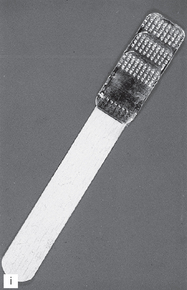
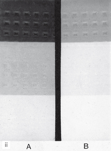
• Monitored for deterioration. This can be done easily using radiographs of a step-wedge phantom:
Processing equipment
• Manual processing requires the use of accurate timers, thermometers and immersion heaters. Instructions on their proper use should be provided.
• Automatic processors require regular replenishment of chemical solutions and regular cleaning, especially of the rollers. All cleaning procedures should be written down including how often they should be carried out.
• Record log confirming that all cleaning procedures have been carried out should be kept.
Working procedures
• Local rules — required in the UK under the Ionising Radiations Regulations 1999 (see Ch. 8). These rules should contain the procedural and operational elements that are essential to the safe use of X-ray equipment, including guidance on exposure times, and as such should contain much of what is relevant to the maintenance of good standards in QA.
• Employers’ written procedures — required in the UK under the Ionising Radiation (Medical Exposure) Regulations 2000 (see Ch. 8).
• Operational procedures or systems of work — these include written procedures that provide for all actions that indirectly affect radiation safety and diagnostic quality, e.g. instructions for the correct preparation and subsequent use of processing chemicals (as explained earlier).
• Procedures log — the QA programme should include the maintenance of a procedures log to record the existence of appropriate Local Rules and Employers’ Written Procedures, together with a record of each occasion on which they are reviewed or modified (ideally every 12 months).
Staff training and updating
As mentioned in Chapter 8, it is a legal requirement under the Ionising Radiation (Medical Exposure) Regulations 2000 that all practitioners and operators are adequately trained and that continuing professional development (CPD) is undertaken. The details of the training required in the UK are given in Chapter 8. The QA programme should incorporate a register of all staff involved with any aspect of radiography and should include the following information:
Audits
Each procedure within the QA programme will include a requirement for written records to be made by the responsible person at varying intervals. In addition, the person with overall responsibility for the QA programme should check the full programme at intervals not exceeding 12 months. This is an essential feature of demonstrating effective implementation of the programme. Clinical audits may include:
QUALITY CONTROL PROCEDURES FOR DIGITAL RADIOGRAPHY
The overall quality control procedures for digital radiography are similar, and in some instances identical, to those required for film-based radiography. They relate to:
Quality control procedures for digital image quality assessment and image processing and manipulation are currently not well defined or documented, although some of the recommendations in the 2005 IPEM Report 91, mentioned earlier, apply to dental digital imaging. Theoretically image quality overall should be improved as:
• Chemical processing errors are eliminated
• Most exposure errors can be compensated for by using computer software particularly when using phosphor plates with their wide latitude, although overexposure of solid-state sensors can cause blooming (see Ch. 7 and Fig. 7.14).
However, radiographic technique errors are just as important as in film-based radiography and need to be monitored. Clinicians using digital radiography are still required to have a quality assurance (QA) programme. The 2001 Guidance Notes make the additional recommendation that because of the ease with which digital radiographs can be retaken, it is essential to ensure that all retakes are properly justified, recorded and included in QA statistics.
Footnote
The requirement for quality assurance and quality control measures in general dental practice applies equally to specialized radiography departments. However, in view of the cost implications, the expensive, sophisticated equipment available for precise quality assurance measurements and accurate monitoring in X-ray departments are often inappropriate to general practice. The practical suggestions in this chapter for film-based radiography, based on the 2001 Guidance Notes, are designed to satisfy the WHO definition by bringing an element of objectivity to quality assurance in practice, but at the same time being simple, easily done and inexpensive.