Chapter 15 Cephalometric radiography
Cephalometric radiography is a standardized and reproducible form of skull radiography used extensively in orthodontics to assess the relationships of the teeth to the jaws and the jaws to the rest of the facial skeleton. Standardization was essential for the development of cephalometry — the measurement and comparison of specific points, distances and lines within the facial skeleton, which is now an integral part of orthodontic assessment. The greatest value is probably obtained from these radiographs if they are traced or digitized and this is essential when they are being used for the monitoring of treatment progress.
MAIN INDICATIONS
The main clinical indications can be considered under two major headings — orthodontics and orthognathic surgery.
Orthodontics
• Initial diagnosis — confirmation of the underlying skeletal and/or soft tissue abnormalities
• Monitoring treatment progress, e.g. to assess anchorage requirements and incisor inclination
• Appraisal of treatment results, e.g. 1 or 2 months before the completion of active treatment to ensure that treatment targets have been met and to allow planning of retention.
When considering these indications, it should be remembered that all radiographs must be clinically justified under current legislation (see Ch. 8). In the UK, indications and selection criteria for cephalometric radiographs are clearly identified in the British Orthodontic Society’s 2001 booklet Orthodontic Radiographs – Guidelines for the Use of Radiographs in Clinical Orthodontics and in the Faculty of General Dental Practice (UK)’s 2004 booklet Selection Criteria in Dental Radiography. These guidelines are designed to assist in the justification process so as to avoid the use of unnecessary radiographs.
EQUIPMENT
Several different types of equipment are available for cephalometric radiography, either as separate units, or as additional attachments to panoramic units. In some equipment the patients are seated, while in others they remain standing. Traditional equipment was designed to use indirect-action radiographic film in an extra-oral cassette as the image receptor. The advent of digital imaging, using phosphor plates and solid-state sensors, has seen the development of new dedicated digital equipment. The basic components of these different types of equipment are described below.
Traditional film-based equipment
This either consists of an additional attachment to a panoramic unit as shown in Figure 15.1, or as a completely separate dedicated unit as shown in Figure 15.2. The basic components include:
• X-ray generating apparatus that should:
• Cephalostat (or craniostat) (see Fig. 15.3) comprising:
• Cassette (usually 18 × 24 cm) containing rare-earth intensifying screens and indirect action film.
• Aluminium wedge filter designed to attenuate the X-ray beam selectively in the region of the facial soft tissues to enable the soft tissue profile to be seen on the final radiograph. This is either attached to the tubehead, covering the anterior part of the beam (the preferred position) or it is included as part of the cephalostat and positioned between the patient and the anterior part of the cassette.
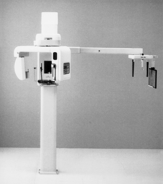
Fig. 15.1 An example of a traditional combined panoramic and cephalostat unit suitable for film-based or phosphor plate imaging.
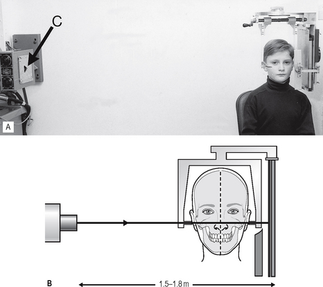
Fig. 15.2A An example of traditional equipment designed for film-based cephalometric radiography showing the cephalostat and X-ray tubehead in fixed positions. The triangular collimator (C) is indicated by the arrow. B Diagram showing the fixed relationship between X-ray tubehead and film, separated by 1.5—1.8 m. The patient is immobilized in the cephalostat with the mid-sagittal plane of the head parallel to the film.
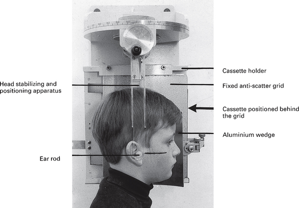
Fig. 15.3 A traditional cephalostat (craniostat) designed for film-based imaging. A fixed anti-scatter grid is included and the aluminium wedge filter positioned between the patient and the grid. The Frankfort plane is marked on the patient’s face.
Digital equipment
Equipment variations exist depending on the type of digital image receptor chosen.
Using phosphor plates
Equipment not incorporating anti-scatter grids, such as combined panoramic/cephalostat units can be converted to digital by simply replacing the film and intensifying screens in the cassette with a suitably sized phosphor plate. As explained in Chapter 14, the grid prevents sufficient photons from reaching the phosphor plate to create an acceptable image. Either the exposure factors (kV) have to be increased or the grid removed.
Using solid-state sensors
Several manufacturers have developed combined panoramic/cephalostat units utilizing specially designed solid-state sensors. An example is shown in Figure 15.4. Sensor design was discussed in Chapter 6 and illustrated in Figure 6.18.
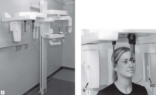
Fig. 15.4A An example of a combined digital panoramic/cephalostat unit—the Planmeca Proline using the Dimax3® solid-state sensor. B Patient positioned and immobilized within the cephalostat unit. Note the solid-state sensor (S) and the secondary collimator (SC) (arrowed).
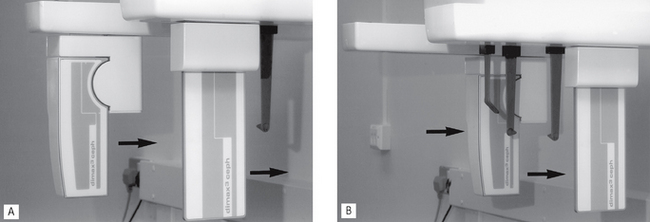
The sensor is obviously not the same size as an 18 × 24 cm cassette and the image cannot be captured in the same way. During the exposure, the X-ray beam and sensor move either horizontally or vertically to scan the patient, as shown in Figure 15.5. The final image therefore takes a few seconds to build up. To ensure that the X-ray beam is the same shape as the CCD array in the sensor and that they are aligned exactly, the beam passes through a secondary collimator, which also moves throughout the exposure, as shown in Figure 15.5.
MAIN RADIOGRAPHIC PROJECTIONS
True cephalometric lateral skull
As stated in Chapter 13, the terminology used to describe lateral skull projections is somewhat confusing, the adjective true, as opposed to oblique, being used to describe lateral skull projections when:
• The image receptor is parallel to the sagittal plane of the patient’s head
• The X-ray beam is perpendicular to image receptor and sagittal plane.
In addition, the word cephalometric should be included when describing the true lateral skull radiograph taken in the cephalostat. This enables differentiation from the non-standardized true lateral skull projection taken in a skull unit, as described in Chapter 14. It is now an accepted convention to view orthodontic lateral skull radiographs with the patient facing to the right, as shown in Figure 15.6.
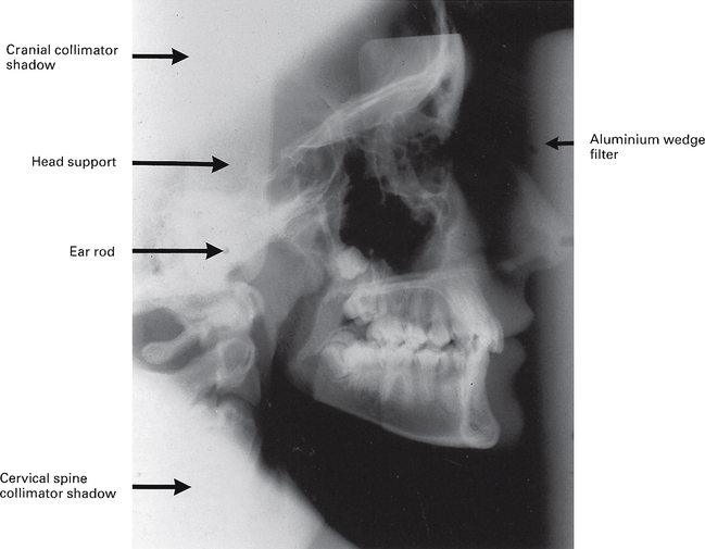
Fig. 15.6 An example of a film-captured true cephalometric lateral skull radiograph. Note the images of the ear rods should ideally appear superimposed on one another. The various shadows of the cephalostat equipment and the collimator are indicated.
Technique and positioning
This can be summarized as follows:
1. The patient is positioned within the cephalostat, with the sagittal plane of the head vertical and parallel to the image receptor and with the Frankfort plane horizontal. The teeth should generally be in maximum intercuspation.
2. The head is immobilized carefully within the apparatus with the plastic ear rods being inserted gradually into the external auditory meati.
3. The aluminium wedge if used, is positioned to cover the anterior part of the image receptor.
4. The equipment is designed to ensure that when the patient is positioned correctly, the X-ray beam is horizontal and centred on the ear rods, (see Fig. 15.6).
Cephalometric tracing / digitizing
This produces a diagrammatic representation of certain anatomical points or landmarks evident on the lateral skull radiograph (see Fig. 15.7). These points are traced on to an overlying sheet of paper or acetate or digitally recorded. Either method allows precise measurements to be made. As a basic system these could include:
• The outline and inclination of the anterior teeth
• The positional relationship of the mandibular and maxillary dental bases to the cranial base
• The positional relationship of the dental bases to one another, i.e. the skeletal patterns
• The relationship between the bones of the skull and the soft tissues of the face.
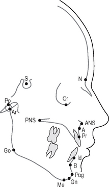
Fig. 15.7 A cephalometric tracing of a lateral skull radiograph showing the main cephalometric points.
Main cephalometric points
The definitions of the main cephalometric points (as indicated in a clockwise direction on the tracing shown in Fig. 15.7) include:
Prosthion (Pr).
The most anterior point of the alveolar crest in the premaxilla, usually between the upper central incisors.
Infradentale (Id).
The most anterior point of the alveolar crest, situated between the lower central incisors.
Supramentale or point B.
The deepest point in the bony outline between the infradentale and the pogonion.
Gnathion (Gn).
The most anterior and inferior point on the bony outline of the chin, situated equidistant from pogonion and menton.
Gonion (Go).
The most lateral external point at the junction of the horizontal and ascending rami of the mandible.
Note: The gonion is found by bisecting the angle formed by tangents to the posterior and inferior borders of the mandible.
Posterior nasal spine (PNS).
The tip of the posterior spine of the palatine bone in the hard palate.
Main cephalometric planes and angles
The definitions of the main cephalometric planes and angles shown in Figure 15.8 include:
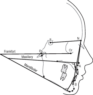
Fig. 15.8 A cephalometric tracing of a lateral skull radiograph showing the main cephalometric planes and angles.
Frankfort plane.
A transverse plane through the skull represented by the line joining porion and orbitale.
Mandibular plane.
A transverse plane through the skull representing the lower border of the horizontal ramus of the mandible.
Maxillary plane.
A transverse plane through the skull represented by a joining of the anterior and posterior nasal spines.
SNA.
Relates the anteroposterior position of the maxilla, as represented by the A point, to the cranial base.
SNB.
Relates the anteroposterior position of the mandible, as represented by the B point, to the cranial base.
ANB.
Relates the anteroposterior position of the maxilla to the mandible, i.e. indicates the anteroposterior skeletal pattern — Class I, II or III.
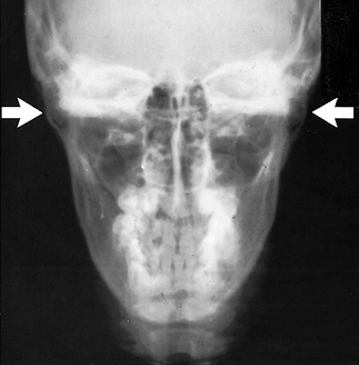
CEPHALOMETRIC POSTEROANTERIOR OF THE JAWS (PA JAWS)
This projection is identical to the PA view of the jaws described in Chapter 14, except that it is standardized and reproducible. This makes it suitable for the assessment of facial asymmetries and for preoperative and postoperative comparisons in orthognathic surgery involving the mandible.
Technique and positioning (Fig. 15.9)
This can be summarized as follows:
1. The head-stabilizing apparatus of the cephalostat is rotated through 90°.
2. The patient is positioned in the apparatus with the head tipped forwards and with the radiographic baseline horizontal and perpendicular to the film, i.e. in the forehead–nose position.
3. The head is immobilized within the apparatus by inserting the plastic ear rods into the external auditory meati.
4. The fixed X-ray beam is horizontal with the central ray centred through the cervical spine at the level of the rami of the mandible (see Figs. 15.9 and 15.10).
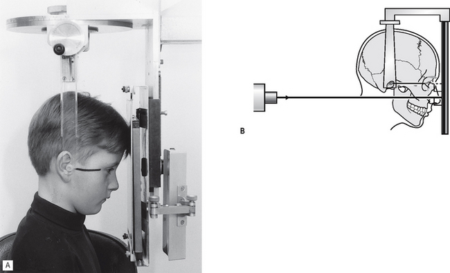
Fig. 15.9A Positioning for the cephalometric PA jaws projection. The patient is in the forehead–nose position, with the radiographic baseline (marked on the face) horizontal and perpendicular to the image receptor. B Diagram of the patient positioning and showing the X-ray beam horizontal and centred through the rami.