Chapter 6 Image receptors
This chapter summarizes the various image receptors used in dentistry to detect X-rays. These include:
RADIOGRAPHIC FILM
Radiographic film has traditionally been employed as the image receptor in dentistry and is still widely used. There are two basic types:
• Direct-action or non-screen film (sometimes referred to as wrapped or packet film). This type of film is sensitive primarily to X-ray photons.
• Indirect-action or screen film, so-called because it is used in combination with intensifying screens in a cassette. This type of film is sensitive primarily to light photons, which are emitted by the adjacent intensifying screens. They respond to shorter exposure of X-rays, enabling a lower dose of radiation to be given to the patient.
Direct-action (non-screen) film
Uses
Direct-action film is used for intraoral radiography where the need for excellent image quality and fine anatomical detail are of importance.
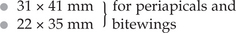
Sizes
Various sizes of film are available, although only three are usually used routinely (see Fig. 6.1).
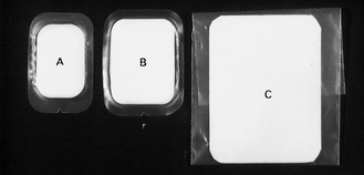
The film packet contents
The contents of a film packet are shown in Figure 6.1. It is worth noting that:
• The outer packet or wrapper is made of non-absorbent paper or plastic and is sealed to prevent the ingress of saliva.
• The side of the packet that faces towards the X-ray beam has either a pebbled or a smooth surface and is usually white.
• The reverse side is usually of two colours so there is little chance of the film being placed the wrong way round in the patient’s mouth and different colours represent different film speeds.
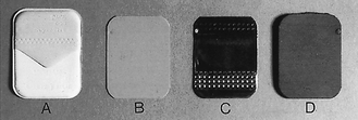
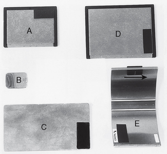
Fig. 6.2 The contents of a film packet. A The outer wrapper. B The film. C The sheet of lead foil. D The protective black paper.
• The black paper on either side of the film is there to protect the film from:
• A thin sheet of lead foil is placed behind the film to prevent:
• The sheet of lead foil contains an embossed pattern so that should the film packet be placed the wrong way round, the pattern will appear on the resultant radiograph. This enables the cause of the resultant pale film to be easily identified (see Ch. 18).
The radiographic film
The cross-sectional structure and components of the radiographic film are shown in Figure 6.3. It comprises four basic components:
• A plastic base, made of clear, transparent cellulose acetate — acts as a support for the emulsion but does not contribute to the final image
• A thin layer of adhesive — fixes the emulsion to the base
• The emulsion on both sides of the base — this consists of silver halide (usually bromide) crystals embedded in a gelatin matrix. The X-ray photons sensitize the silver halide crystals that they strike and these sensitized silver halide crystals are later reduced to visible black metallic silver in the developer (see Ch. 7)
• A protective layer of clear gelatin to shield the emulsion from mechanical damage.
Film orientation
The film has an embossed dot on one corner that is used to help orientation. Its position is marked on the back of the packet or can be felt as a raised dot on the front. The side of the film on which the dot is raised is always placed towards the X-ray beam. When the films are mounted, this raised dot is towards the operator and the films are then arranged anatomically and viewed as if the operator were facing the patient.
Indirect-action film
Uses
Film/screen combinations are used as image detectors whenever possible because of the reduced dose of radiation to the patient (particularly when very fine image detail is not essential). The main uses include:
Indirect-action film construction
This type of film is similar in construction to direct-action film described above. However, the following important points should be noted:
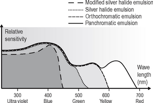
• The silver halide emulsion is designed to be sensitive primarily to light rather than X-rays.
• Different emulsions are manufactured which are sensitive to the different colours of light emitted by different types of intensifying screens (see later). These include:
The relative spectral sensitivity of these four different film emulsions is shown in Figure 6.4.
Characteristics of radiographic film
This section summarizes the more important theoretical terms and definitions used to describe how radiographic film responds to exposure to X-rays.
Optical density (OD)
Optical density is the term used for describing the degree of film blackening and can be measured directly using a densitometer. In diagnostic radiology the range of optical densities is usually 0.25–2.5. There are no units for optical density.
Characteristic curve
The characteristic curve is a graph showing the variation in optical density (degree of blackening) with different exposures. Typical characteristic curves for direct-action (non-screen) and indirect-action (screen) film are shown in Figure 6.5. This curve describes several of the film’s properties.
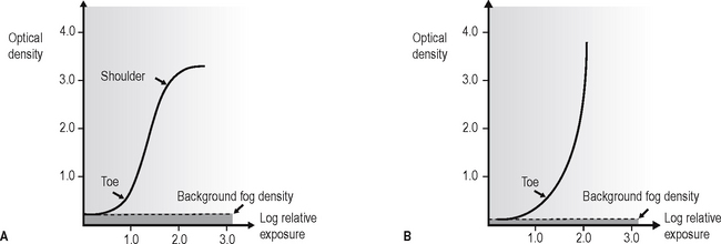
Background fog density
This is the small degree of blackening evident even with zero exposure. This is due to:
If the film has been stored correctly (see later), this background fog density should be less than 0.2 (see Fig. 6.5).
Film speed
This is the exposure required to produce an optical density of 1.0 above background fog (see Fig. 6.6). Thus, the faster the film, the less the exposure required for a given film blackening and the lower the radiation dose to the patient.
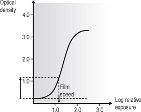
Fig. 6.6 The characteristic curve of an indirect-action (screen) film showing the film speed — the exposure required to produce an optical density of 1.0 above background fog.
Film speed is a function of the number and size of the silver halide crystals in the emulsion. The larger the crystals, the faster the film but the poorer the image quality.
In clinical practice, the fastest films consistent with adequate diagnostic results, either D speed or more usually nowadays the faster E or F speed, should be used.
Film sensitivity
This is the reciprocal of the exposure required to produce an optical density of 1.0 above background fog. Thus, a fast film has a high sensitivity.
Film latitude
This is a measure of the range of exposures that produces distinguishable differences in optical density, i.e. the linear portion of the characteristic curve (see Fig. 6.7). The wider the film latitude the greater the range of object densities that may be seen.
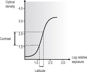
Film contrast
This is the difference in optical density between two points on a film that have received different exposures (see Fig. 6.7).
Film gamma and average gradient
Film gamma is the maximum gradient or slope of the linear portion of the characteristic curve. This term is often quoted but is of little value in radiology because the maximum slope (steepest) portion of the characteristic curve is usually very short.
Average gradient is a more useful measurement and is usually calculated between density 0.25 and 2.0 above background fog (see Fig. 6.8).
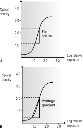
Fig. 6.8 Characteristic curves showing A film gamma and B average gradient of an indirect-action (screen) film.
Thus the film gamma or average gradient measurement determines both film latitude and film contrast as follows:
Resolution
Resolution, or resolving power, is a measure of the radiograph’s ability to differentiate between different structures that are close together. Factors that can affect resolution include penumbra effect (image sharpness), silver halide crystal size and contrast. It is measured in line pairs (lp) per mm. Direct-action film has a resolution of approximately 10 lp per mm and indirect-action film a resolution of about 5 lp per mm.
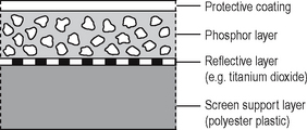
Intensifying screens
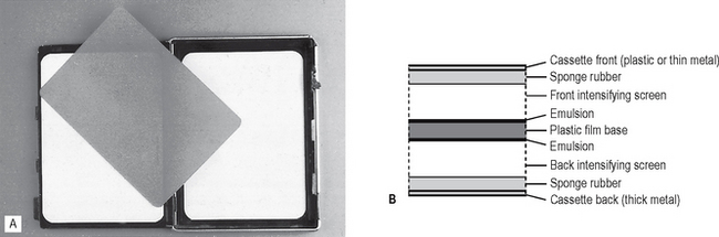
Intensifying screens consist of fluorescent phosphors, which emit light when excited by X-rays, embedded in a plastic matrix. The basic construction and components of an intensifying screen are shown in Figure 6.9.
Action
Two intensifying screens are used — one in front of the film and the other at the back. The front screen absorbs the low-energy X-ray photons and the back screen absorbs the high-energy photons. The two screens are therefore efficient at stopping the transmitted X-ray beam, which they convert into visible light by the photoelectric effect (described in Ch. 2). One X-ray photon will produce many light photons which will affect a relatively large area of film emulsion. Thus, the amount of radiation needed to expose the film is reduced but at the cost of fine detail; resolution is decreased. The ultraviolet system was developed to improve resolution by reducing light diffusion and having virtually no light crossover through the plastic film base (see Fig. 6.10).
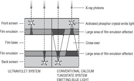
Fig. 6.10 Diagram showing the action of conventional calcium tungstate and ultraviolet systems. Note the small cone of ultraviolet light with no cross-over through the film base, compared to the large cone of blue light and marked cross-over from the calcium tungstate phosphors. These differences result in better resolution and image sharpness with ultraviolet systems.
Useful definitions
The following terms are used to describe intensifying screens:
• Conversion efficiency — the efficiency with which the phosphor converts X-rays into light
• Absorption efficiency — the ability of the phosphor material to absorb X-rays
• Screen efficiency — the ability of the light emitted by the phosphor to escape from the screen and expose the film
• Screen speed — the time taken for the screen to emit light following exposure to X-rays. The faster the screen, the lower the radiation dose to the patient
• Packing density — the ability of the phosphor to pack closely together resulting in thin screens and less light divergence.
Fluorescent materials
Three main phosphor materials are, or have been, used in intensifying screens:
• Rare earth phosphors including gadolinium and lanthanum
• Yttrium (a non-rare earth phosphor but having similar properties)
Rare earth and related screens
Modern screens employ these phosphors which produce very fast screen speeds, enabling a substantial reduction in radiation dose to patients, without excessive loss of image detail. The main points can be summarized as follows:
l The rare earth group of elements includes:
• The term rare earth is used because it is difficult and expensive to separate these elements from earth and from each other, not because the elements are scarce.
• These phosphors only fluoresce properly when they contain impurities of other phosphors, e.g. gadolinium plus 0.3% terbium. Typical screens include:
• Terbium-activated screens emit GREEN light, while thulium-activated screens emit BLUE light (see Fig. 6.11).
• Yttrium (Z = 39), the rare earth related phosphor, in the form of pure yttrium tantalate (YtaO4) emits ULTRAVIOLET light (see Fig. 6.11).
• Rare earth and related screens are approximately five times faster than calcium tungstate screens. The amount of radiation required to produce an image is therefore considerably reduced, but they are relatively expensive.
• Several different screens of each phosphor, each producing a different image system speed, are available:
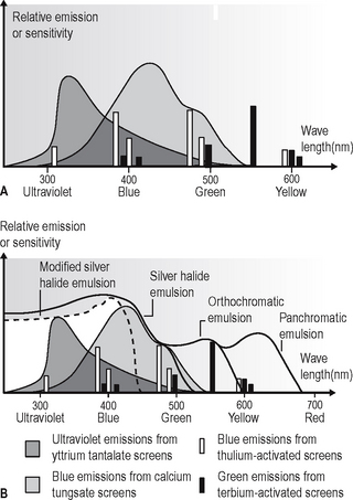
Fig. 6.11A Graph showing the relative spectral emissions of different types of intensifying screens. B Graph showing the spectral sensitivity of different types of film combined with the relative spectral emissions of different types of intensifying screens.
| Screen type | Image system speed |
|---|---|
| Detail or Fine | 100 |
| Fast detail or Medium | 200 |
| Rapid or Fast | 400 |
| Super rapid | 800 |
• It is important to use the appropriate films with their correctly matched screens.
Calcium tungstate screens
The original material used but now no longer recommended. The main points can be summarized as follows:
• The speed of these screens depends upon:
• The faster the screen, the lower the radiation dose to the patient but the less the detail of the final image
• All calcium tungstate screens emit BLUE light and must be used with blue-light sensitive monochromatic radiographic film (see Fig. 6.11).
Cassettes
Types
Cassettes are made in a variety of shapes and sizes for different projections. A selection is shown in Figure 6.12.
Construction
Despite their different shapes, the construction of the cassettes is very similar. They consist usually of a light-tight aluminium or carbon fibre container with the radiographic film sandwiched tightly between two intensifying screens (see Fig. 6.13). Any loss in film/screen contact will result in degradation of the final image.
Important practical points to note
Film storage
All radiographic film deteriorates with time and manufacturers state expiry dates on film boxes as a guide. However, this does not mean that the film automatically becomes unusable after this date. Storage conditions can have a dramatic effect on the deterioration rate. Ideally films should be stored:
Screen maintenance
Intensifying screens should last for many years if looked after correctly. Maintenance should include:
• Regular cleaning with a proprietary cleaning agent
• Careful handling to avoid scratching or damaging the surface
These aspects are discussed further in Chapter 18.
DIGITAL RECEPTORS
There are two types of direct digital image receptors available, namely:
Uses
Both types of sensors can be used for intraoral (periapical and bitewing radiograph) and extraoral radiography including panoramic and skull radiography. Only phosphor storage plates are available for occlusal and oblique lateral radiography as it is currently too expensive to manufacture sufficiently large solid-state sensors.
Solid-state sensors
Intraoral sensors
The intraoral sensors are small, thin, flat, rigid rectangular boxes usually black in colour and similar in size to intraoral film packets as shown in Figure 6.14. They vary in thickness from about 5–7 mm. Most sensors are cabled to allow data to be transferred directly from the mouth to the computer. Several systems are now available, examples include Gendex Visualix®, Planmeca dixi2® and Kodak RVG 6000 (see Fig. 6.14).
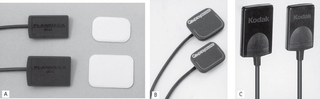
Fig. 6.14 Examples of modern solid-state sensors. A Planmeca dixi2 ® and conventional film packets to show their comparative size. B Gendex Visualix®. C Kodak RVG 6000.
(kindly provided by Mr R. France)
For ease of clinical use the sensor cables are usually 1–2 m long and plug into a remote docking station which can be conveniently attached to the tubehead supporting arm (see Fig. 6.15). A separate cable then connects the docking station to the computer.
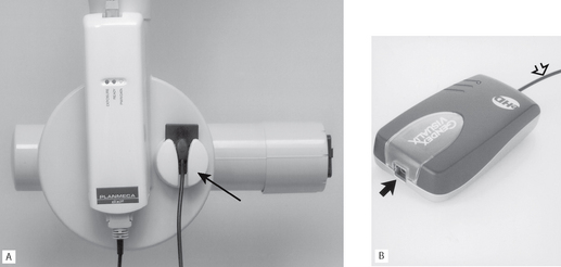
Fig. 6.15 Examples of docking stations. A Planmeca dixi2® attached to an X-ray tubehead. Note the little holder for conveniently supporting the sensor (arrowed). B Gendex Visualix®. The sensor plugs into the arrowed port. The open arrowed cable connects to the computer
(kindly provided by Mr R. France).
A cable-free system is also available. The Schick CDR Wireless™ sensor transmits radiowaves from the mouth to a remote base station which is connected by a cable to the computer. This removes the inconvenience the cable can create clinically, but additional electronics make the sensor slightly more bulky.
The solid-state sensors are NOT autoclavable. When used clinically they all need to be covered with a protective plastic barrier envelope for infection control purposes (see Ch. 9).
Construction and design
The sensors consist of tiny silicon chip-based pixels and their associated electronics encased in a plastic housing. Underlying technology involves either:
CCD (charge-coupled device)
Individual pixels, consisting of a sandwich of P and N-type silicon, are arranged in rows and columns called an array or matrix, above which is a scintillation layer made of similar materials to the rare-earth intensifying screens. The basic design is shown in Figure 6.16. The X-ray photons that hit the scintillation layer are converted to light. The light interacts via the photoelectric effect with the silicon to create a charge packet for each individual pixel, which is concentrated by the electrodes.
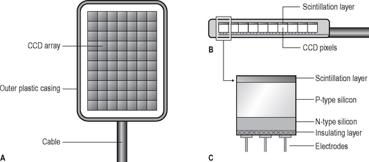
Fig. 6.16 Diagrams illustrating the basic construction of an intraoral CCD sensor. A The imaging surface showing the pixel array. B Sensor from the side showing the scintillation layer. C An individual pixel consisting of a sandwich of N- and P-type silicon.
The charge pattern formed from the individual pixels in the matrix represents the latent image. The image is read by transferring each row of pixel charges from one row to the next. At the end of its row, each charge is transferred to a read-out amplifier and transmitted down the cable as an analogue voltage signal to the computer’s analogue-to-digital converter, often located in the docking station. Each sensor consists of between 1.5 million and 2.5 million pixels and pixel sizes vary from 20 microns to 70 microns.
CMOS (complimentary metal oxide detectors)
These sensors are similar in construction to CCDs and consist of an array of pixels but they differ from CCDs in the way that the pixel charges are read. Each CMOS pixel is isolated from its neighbour and directly connected to a transistor. The charge packet from each pixel is transferred to the transistor as a voltage enabling each individual pixel to be assessed separately.
Extraoral sensors
Extraoral sensors contain CCDs in long, thin linear arrays. They are a few pixels wide and many pixels long. The CCD array is incorporated into two different designs of sensor:
• Flat cassette-sized sensors designed to be retro-fitted into existing film-based panoramic equipment to replace conventional cassettes. For example, most film-based panoramic units can be converted to digital by simply installing a flat digital sensor such as the original Trophy Digipan sensor (see Fig. 6.17) or Schick CDRPan™.
• Individually designed sensors as part of completely new solely digital panoramic or skull equipment such as the Schick CDRPanX or the Planmeca dimax3® (see Fig. 6.18).
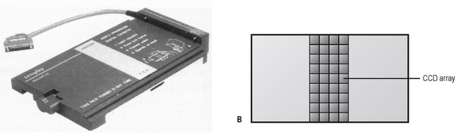
Fig. 6.17A The original Trophy Digipan® CCD sensor for retro-fitting to panoramic equipment. B Diagram showing the basic with a long thin array of CCDs.
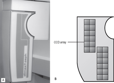
Fig. 6.18A Specifically designed Planmeca dimax3® sensor for cephalometric radiography (see Ch. 15). B Diagram showing the basic design with two long thin arrays of CCDs.
Although the outward appearances of these sensors is very different, both designs work in a similar fashion. The long narrow pixel array is aligned with a narrow slit-shaped X-ray beam and the equipment scans across the patient. This scanning motion takes several seconds to scan the skull and is discussed in more detail in Chapter 15.
Photostimulable phosphor storage plates
These digital sensors consist of a range of imaging plates that can be used for both intraoral and extraoral radiography. The plates are not connected to the computer by a cable. Several systems are available and include the DentOptix™ (Gendex) and the Vistascan™ (Durr) and Digora® Optime (intraoral) and PCT (extraoral) (Soredex).
A range of intraoral and extraoral plate sizes are available with these systems, identical in size to conventional periapical, occlusal, oblique lateral, panoramic and skull films (see Fig. 6.19). Once cleared (erased), the plates are reusable. Intraoral plates need to be inserted into protective barrier envelopes for control of infection purposes (see Fig. 6.20A).
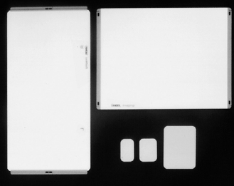
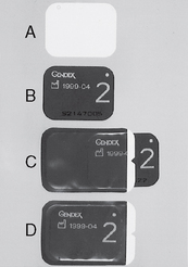
Fig. 6.20A The white imaging side of a DenOptix™ phosphor plate. B The reverse side of the plate. C The plate being inserted into the protective barrier envelope — note the reverse side of the plate is visible through the clear side of the envelope. D The plate in the envelope ready for clinical use.
Plate construction and design
The plates typically consist of a layer of barium fluorohalide phosphor on a flexible plastic backing support, as shown in Figure 6.21.
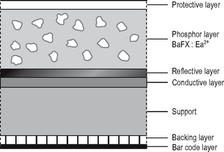
As with using film, image production is not instantaneous with this type of image receptor. Two distinct stages are involved, namely:
• The phosphor layer absorbs and stores the X-ray energy that has not been attenuated by the patient.
• The image plate is then placed in a reader where it is scanned by a laser beam. The stored X-ray energy in the phosphor layer is released as light which is detected by a photo-multiplier tube and converted into a voltage which is relayed to the computer and displayed as a digital image. This is described in more detail in Chapter 7.