Chapter 24 Implant assessment
INTRODUCTION
The restoration of edentulous and partially dentate jaws using a variety of implant-retained prostheses has become a common clinical procedure in recent years. The implants are usually made of titanium and are described as either:
• Endosteal — placed in the bone. These are manufactured in a variety of shapes — screw, smooth-sided or plate-form, and essentially replace the roots of one or more teeth
• Subperiosteal — placed on the bone, under the periosteum and secured in place with screws.
This chapter concentrates on endosteal dental implants which are more commonly used, particularly since P. I. Brånemark’s clinical research on the concept of osseointegration which he defined as a direct connection between living bone and a load carrying endosseous implant at the light microscopic level. There are many different endosteal implant systems available, and it is beyond the scope of this book to discuss all the systems and their various advantages and disadvantages. The Brånemark system, described here, is probably the best known and has been researched over the longest period demonstrating acceptable 20-year success rates. Most currently used implant systems can be viewed as design modifications to this basic concept.
However, whatever the system used, radiology plays an essential role in preoperative treatment planning, postoperative follow-up and success evaluation.
The Brånemark system
Treatment usually involves either a two-stage or a one-stage (non-submerged) surgical procedure followed by the restorative phase. Initially, in the two-stage technique the fixture is placed in vital bone ensuring a precision fit. The cover screw is screwed into the top of the fixture to prevent downgrowth of soft and hard tissue into the internal threaded area. The fixture is then left buried beneath the mucosa for 3–6 months. (It is important during this initial healing period to avoid loading the fixture although early loading protocols are being used in certain clinical circumstances.) The fixture is then surgically uncovered, the cover screw removed and the abutment (the transmucosal component) connected to the fixture by the abutment screw. An hexagonal anti-rotation device is incorporated into the top of the fixture. The gold cylinder, an integral part of the final restorative prosthesis, is finally connected to the abutment by the gold screw. A standard Brånemark implant is illustrated in Figure 24.1.
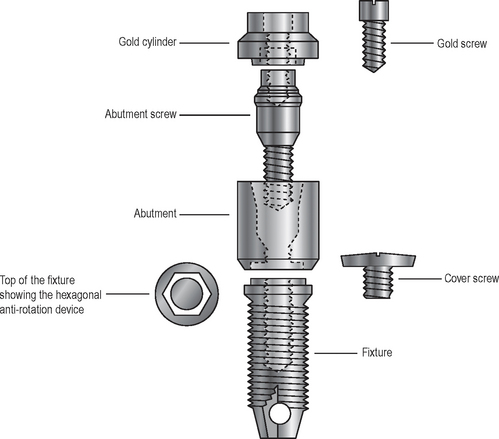
Fig. 24.1 Diagram showing the basic Brånemark system components for a standard endosseous implant. Note: there is a variety of different abutments and restorative elements available that attach to the hexagonal top of the standard fixture.
Modifications to this basic design include slightly roughened implant surfaces to improve bone to implant contact and more stable, secure abutment/implant connection systems employing internal connections rather than the classic flat-top hexagon described above. A variety of different abutments and connecting restorative elements are available for different clinical situations.
MAIN INDICATIONS
Replacement of missing teeth in patients with:
• Healthy dentitions which have suffered tooth loss because of trauma
• Developmentally missing teeth
• Remaining teeth not suitable as bridge abutments
• Severe ridge resorption making the wearing of dentures difficult
• Cleft palates and insufficient remaining teeth to support a denture/obturator
TREATMENT PLANNING CONSIDERATIONS
Clinical examination
A thorough clinical examination using study casts, and an overall evaluation of the patient are essential, as good case selection is imperative for the long-term success of implants. A multidisciplinary approach involving surgeons, prosthodontists and dental technicians is often adopted because of the many important factors that need to be taken into account, including:
• The patient’s age, general health and motivation
• The condition and position of the remaining teeth (if present), including their occlusion
• The status of the periodontal tissues and the level of oral hygiene
• The condition — quality and quantity — of the edentulous mandibular or maxillary alveolar bone
RADIOGRAPHIC EXAMINATION
Although guidelines have been published by both the American Academy of Oral and Maxillofacial Radiology in 2001 and the European Association for Osseointegraion in 2002, there is still some disagreement on selection criteria in individual clinical situations. In addition, other variables make generalized recommendations difficult. Examples of these include:
• The experience of the operator
• The thoroughness of the clinical examination including the use of ridge-mapping techniques
In 2004 the Faculty of General Dental Practice (UK)’s Selection Criteria in Dental Radiography booklet concluded that there is fact only a very small evidence base on which to formulate guidelines for the use of radiographs in implant dentistry.
There are a range of investigations that are suitable in different clinical situations. Clinical choice may well depend on availability of facilities. Investigations include:
• Cross-sectional linear tomography programmes available with some modern panoramic machines (see Ch. 17)
• Multi-directional (e.g. spiral) cross sectional tomography described in Chapter 16 (see Fig. 24.2)
• Cone beam CT. This recently developed, low dose, digital volume tomographic technique described in Chapter 19 is ideal for implant assessment and is likely to become the imaging modality of choice (see Figs 24.3 and 24.4). Computer manipulation enables the production of cross-sectional, panoramic and three-dimensional reconstructed images
• Computed tomography (CT). Specific dental computer programmes, designed for implant planning, have been written that are compatible with medical CT. This usually involves about 30 axial scans per jaw, each 1.5mm thick. This information can then undergo computer manipulation, as with cone beam CT to produce reformatted cross-sectional, panoramic and three-dimensional reconstructed images as shown in Figure 24.5. The radiation dose to the patient is considerably higher when compared to other techniques
• Magnetic resonance (MR). This offers the advantages of not using ionizing radiation and producing sections in any desired plane without reformatting, as shown in Figure 24.6.
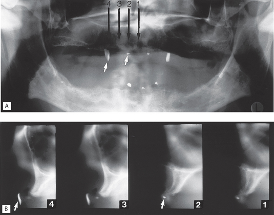
Fig. 24.2 Pre-implant assessment using the Scanora® multidirectional tomographic machine. A Panoramic radiograph of an edentulous patient showing various radiopaque localization markers (attached to the denture). B 4-mm cross-sectional (transverse) spiral tomographic images of the  region. The location of each cross-sectional image is indicated on the panoramic radiograph. The radiopaque markers in the
  and
and  regions are arrowed on both figures and are in focus on the tomographic slices.
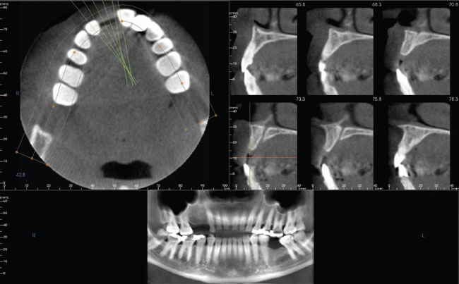
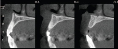
Fig. 24.3 Examples of pre-implant assessment cone beam CT images of the maxilla using the i-CAT™. A Three image screens are available simultaneously on the monitor including axial, panoramic and a series of cross-sectional (or trans-axial) images. B Three life-size cross-sectional images.
(Reproduced with kind permission of Imaging Sciences International, Inc.)
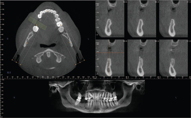
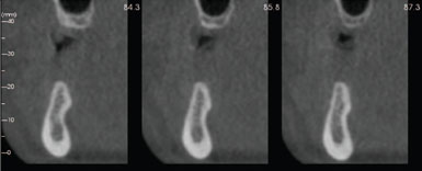
Fig. 24.4 Examples of pre-implant assessment cone beam CT images of the mandible using the i-CAT™. A Monitor images and B Three life-size cross-sectional images.
(Reproduced with kind permission of Imaging Sciences International, Inc.)
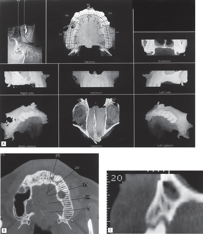
Fig. 24.5 Examples of CT images created by multiplanar reformatting used for pre-implant assessment in the maxilla. A Set of three-dimensional reconstructed images. B One axial slice showing the position of the various reconstructed cross-sectional images. C One reconstructed cross-sectional slice — number 20 from the axial slice shown in B.
(Kindly supplied by Dr A. Sidi.)
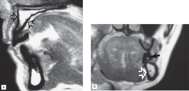
Fig. 24.6A Sagittal section MR scan showing the buccopalatal width and height of the edentulous anterior maxilla (arrowed). B Cross-sectional MR image showing an edentulous left mandible (open arrow) and the stent containing the gadolinium marker (black arrow). The inferior dental canal is clearly evident.
(Images kindly supplied by Mr Crawford Gray.)
Radiographic information provided
These various radiographic investigations are used to show:
• The position and size of relevant normal anatomical structures, including the:
• The shape and size of the antra, including the position of the antral floor and its relationship to adjacent teeth
• The presence of any underlying disease
• The presence of any retained roots or buried teeth
• The quantity of alveolar crest/basal bone, allowing direct measurements of the height, width and shape
Important points to note
• Cross-sectional imaging is important to provide information on the width and quality of the alveolar bone and the location of anatomical structures. The choice of imaging modality will obviously depend on the availability of facilities. The more complex the clinical case, the more comprehensive the radiographic assessment needs to be.
• Plastic stents containing radiopaque markers are often required for accurate localization of cross-sectional images. Gadolinium markers are used with MR (see Fig. 24.6).
• Radiation dose from medical CT imaging is many times greater than from low dose cone beam CT (see Ch. 19) or multidirectional tomography.
• CT and cone beam CT data can be manipulated and reformatted to produce life-size cross-sectional images, three-dimensional images and can provide radiographic density values for cortical and cancellous bone. Both systems are compatible with SIM/Plant specialized software (Columbia Scientific Inc.) which enables simulated implants to be inserted and viewed on a computer to assess size and angulation.
• The magnification on multi directional cross-sectional tomographs varies from one machine to another, but for any particular unit it is fixed and uniform, e.g. Scanora® slices are all magnified by a factor of 1.7.
POSTOPERATIVE EVALUATION AND FOLLOW-UP
Postoperative evaluation can be carried out immediately after surgery and usually after the initial 4–6 months healing period. Further clinical evaluation of the success or otherwise of the implant, including radiographic assessment, should be carried out on an annual basis for the first few years and then bi-annually. Geometrically accurate paralleling technique periapicals (either film-based or digital) are most commonly used. Note: The accuracy can be checked by examining the geometric thread pattern of the fixture.
Criteria for success
Ideally, implants should be evaluated against standardized success criteria and not simply assessed for their survival. Several criteria for success have been put forward over the years for the different implant systems. Those favoured by the author, and cited frequently in the literature, are those proposed by Albrektsson in 1986. These include:
1. That an individual, unattached implant is immobile when tested clinically.
2. That a radiograph does not demonstrate any evidence of peri-implant radiolucency.
3. That vertical bone loss be less than 0.2mm annually following the implant’s first year of service.
4. That individual implant performance be characterized by an absence of signs and symptoms such as pain, infection, neuropathies, paraesthesia or violation of the inferior dental canal.
5. That, in the context of the above, a success rate of 85% at the end of a 10-year period be the minimum criteria for success.
Radiographic evaluation (see Figs 24.7, 24.8 and 24.9)
Radiographs allow evaluation of criteria 2 and 3, but also are used to assess:
• The position of the fixture in the bone and its relation to nearby anatomical stuctures
• Healing and integration of the fixture in the bone
• The peri-implant bone level and any subsequent vertical bone loss — threaded fixtures allow easy measurement if radiographs are geometrically accurate
• Development of any associated disease, e.g. perimplantitis
• The fit of the abutment to the fixture
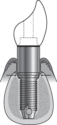
Fig. 24.7 Diagram showing (1) successful osseointegration — the bone/implant interface does not have fibrous tissue interposed, it is a direct contact and attachment between bone and the metallic implant surface, (2) minimal bone loss around the top of the implant, (3) no evidence of peri-implantitis and (4) a close fit of the abutment to the fixture (arrowed). These ideal features apply to the fixture and the surrounding tissues whatever type of abutment and restorative elements are chosen.
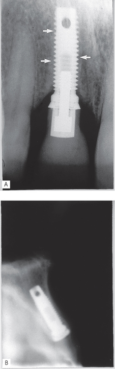
Fig. 24.8A Periapical showing successful osseointegration, 2 years after implant placement. Note the bone/implant interface (arrowed), there is no radiolucency in between. B Cross-sectional spiral tomographic slice in the  region immediately after surgery showing the buccopalatal position and angulation of the implant.
(Kindly supplied by Mr L. Howe.)
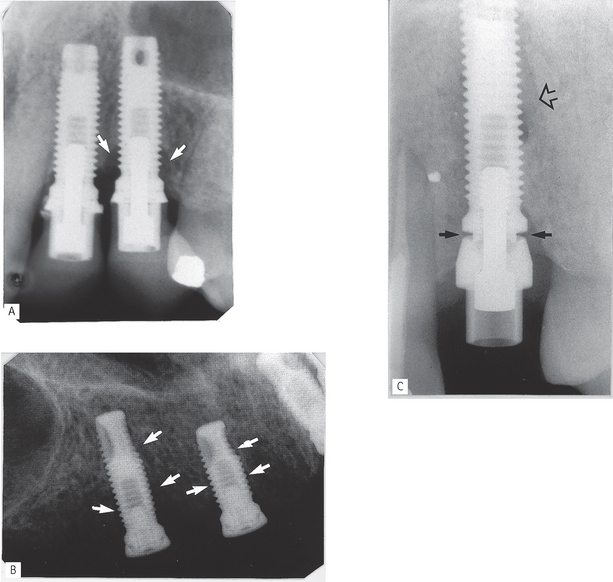
Fig. 24.9A Periapical showing vertical bone loss (arrowed) around the thread of the implant replacing  , but virtually no bone loss around the implant replacing
  . B Periapical showing unsuccessful osseointegration. Note the radiolucent line between surrounding bone and the implants (arrowed), particularly mesially on the implant replacing
  . C Periapical showing incorrect seating of the abutment on the fixture (solid arrows) and residual radiolucency from previous periapical area (open arrow).
(Examples kindly supplied by Prof R. Palmer, Mr Saravanamuttu and Mr L. Howe.)
FOOTNOTE
The limited nature of the information provided by conventional two-dimensional radiographs on the width or thickness of the alveolar bone cannot be overemphasized. Inadequate clinical and radiographic assessment of possible implant sites, before surgery, may lead to implant failure and more seriously, to temporary or permanent nerve damage and possible litigation.