Chapter 16 Tomography
INTRODUCTION
Tomography is a specialized technique for producing radiographs showing only a section or slice of a patient. A useful analogy is to regard the technique as dividing up the patient like a loaf of sliced bread (see Fig. 16.1). Each tomograph (or slice of bread) shows the tissues within that section sharply defined and in focus. The section is thus referred to as the focal plane or focal trough. Structures outside the section (i.e. the rest of the loaf) are blurred and out of focus. By taking multiple slices, three-dimensional information about the whole patient can be obtained.
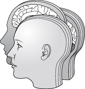
Fig. 16.1 Diagram illustrating the analogy of tomography dividing the patient up like a loaf of sliced bread.
Production of each conventional tomographic slice requires controlled, accurate movement of both the X-ray tubehead and the film during the exposure, thereby differing from all the techniques described in previous chapters. Originally sections were obtained in either the sagittal or coronal planes (see Fig. 16.2), but modern equipment now allows tomography in other planes as well.
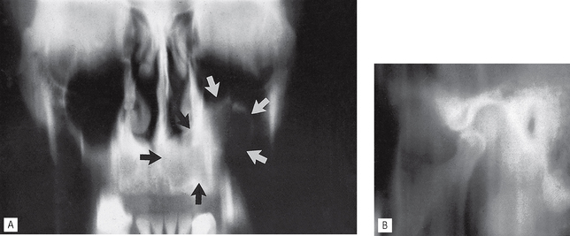
Fig. 16.2A A linear tomograph in the coronal plane of the antrum and facial skeleton showing an antral tumour (arrowed). B A linear tomograph in the sagittal plane of the left TMJ. In both examples, the tissues imaged in the tomographic sections are sharply defined and in focus, while the unwanted structures are blurred out. Note the vertical straight-line blurring on both images.
Conventional tomography has essentially been superseded in medical radiography by the development of computed tomography (CT). It is however still important in dentistry, forming the basis of dental panoramic tomography (see Ch. 17) and multifunctional dental and maxillofacial tomographic machines, such as the Scanora®, or the Tomax® Ultrascan.
The concept of slice or sectional images is also important to appreciate because it forms the basis of many of the modern imaging modalities, described in Chapter 19, that are being used increasingly in dentistry particularly cone beam CT (CBCT).
ORIGINAL INDICATIONS
The original clinical indications for conventional tomographic sectional images in dentistry include:
• Assessment of jaw height, thickness and texture before inserting implants (see Ch. 24)
• Postoperative evaluation of implants
• Assessment of the antra including the position of displaced teeth and foreign bodies
• Evaluation of grossly comminuted facial fractures to determine all the fracture sites
• Assessment of the extent of orbital blow-out fractures
• As an additional investigation of the TMJ and condylar head — particularly useful if patients were unable to open their mouths, since most other radiographs of the TMJ require the mouth to be open (see Ch. 31)
THEORY
Tomographic movement
As stated, tomography requires controlled, accurate movement of both the X-ray tubehead and the film. They are therefore linked together. During the exposure, the X-ray tubehead moves in one direction around the patient while the film moves in the opposite direction, as shown in Figure 16.3. The point (O) at the centre of this rotating movement will appear in focus on the resultant radiograph, since its shadow will appear in the same place on the film throughout the exposure. All other structures will appear blurred or out of focus.
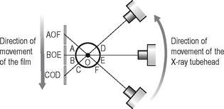
Fig. 16.3 Diagram illustrating the principle of tomographic movement. The X-ray tubehead moves in one direction while the film moves in the opposite direction. Points A,B,C,D,E and F will all appear on different parts of the film and thus will be blurred out, while point O, the centre of rotation, will appear in the same place on the film throughout the exposure and will therefore be sharply defined.
Types of tomographic movement
During tomography, equipment has been designed to move in one of five ways, as shown in Figure 16.4:
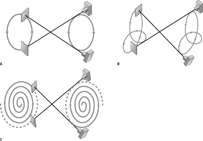
Fig. 16.4 Diagrams showing various types of tomographic movement. A Circular or elliptical. B Hypocycloidal. C Spiral. Note that the centre of rotation remains the same in each case; it is only the movement of the equipment that becomes more complicated.
In each case the centre of rotation remains the same, it is only the movement of the equipment that becomes more complicated. Linear movement is the simplest and easiest to illustrate and is described later. Its main disadvantage is that it produces straight-line blurred shadows of unwanted structures (see Fig. 16.2). The other types of equipment movement have been developed to produce tomographs of better definition with more blurring of unwanted structures making them less obvious on the final film.
BROAD-BEAM LINEAR TOMOGRAPHY
The principle of tomography illustrated in Figure 16.3 shows a very thin X-ray beam producing one point (O) — the centre of rotation — in focus on the film. To produce a section or slice of the patient in focus, a broad X-ray beam is used. For each part of the beam, there is a separate centre of rotation, all of which lie in the same focal plane. The resultant tomograph will therefore show all these points sharply defined. The principle of broad-beam tomography is illustrated in Figure 16.5.
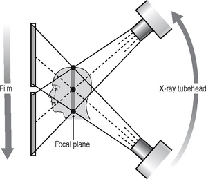
Fig. 16.5 Diagram showing the principle of broad-beam tomography. Using a broad beam there will be multiple centres of rotation (three are indicated: •) all of which will lie in the shaded zone. As all the centres of rotation will be in focus, this zone represents the focal plane or section of the patient that will appear sharply defined on the resultant tomograph.
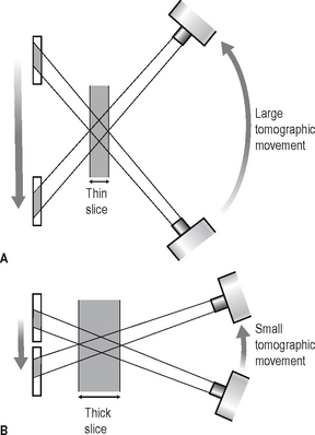
Width/thickness of the focal plane
The thickness of the focal plane is determined by the amount of movement, or angle of swing, of the equipment. As shown in Figure 16.6, the larger the angle of swing, the thinner the section in focus, while the smaller the angle of swing the thicker the section.
Equipment (Fig. 16.7)
Linear tomography of the skull can be performed using the Craniotome®, described in Chapter 14, with the following modifications:
1. A rigid connecting bar is inserted to join the X-ray tubehead and the cassette holder (see Fig. 16.7).
2. The brake on the film–tubehead assembly is released. This frees the assembly, enabling it to move in the vertical plane during the exposure.
3. The position of the fulcrum or pivot of the connecting bar can be adjusted accurately. This alters the centre of rotation and thus the section of the patient to be imaged.
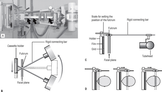
Fig. 16.7A The Craniotome® with rigid tomographic bar attached (black arrows). B Diagram showing the fulcrum and the relative movements of the linked X-ray tubehead and cassette holder. C Diagram showing the fulcrum and measurement scale for selecting different sections. D Diagram showing the fulcrum positioned in line with the different sections of the patient to be imaged.
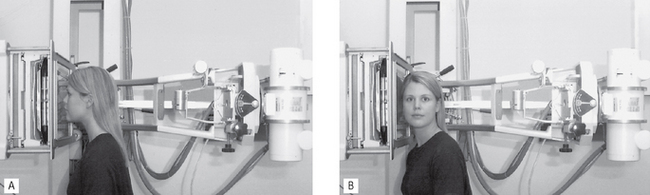
Patient positioning
The patient is positioned within the skull unit. The exact positioning of the patient’s head in either the coronal or sagittal planes depends on the precise area under investigation. Examples are shown in Figure 16.8.
Specialized tomographic units
As mentioned earlier, several specialized dental tomographic units have been developed in recent years. One example is Soredex’s Scanora® unit, which is described below. It is a multifunctional unit enabling tomographs of the dental and maxillofacial region to be obtained in many different planes. The equipment (see Fig. 16.9) consists of patient chair, vertical control panel, and tubehead and cassette-carriage assembly linked together and positioned at either ends of a C-arm and placed in a rotating unit. This arrangement allows the freedom for a large number of dental and maxillofacial imaging procedures and projections to be selected, all of which are computer controlled and automatically executed. The resultant images, produced using complex broad beam spiral tomography (see Fig. 16.4), have better definition and higher resolution than simple linear tomographs.
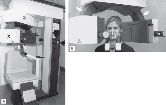
Fig. 16.9A The original film-based Scanora tomographic unit. The X-ray tubehead (X), cassette-carriage assembly (C) and rotating unit (R) are all indicated. B Patient positioned in the unit; note the light-markers on the face. The linking C-arm is arrowed.
Recent developments have seen the Scanora® upgraded for digital imaging using phosphor plate technology. Following exposure the plate is read (see Ch. 7) in situ and the information relayed to the computer for visual display on the monitor.
Range of investigations
The full range of investigations possible using the Scanora® (at present over 600), and the other specialized units available, is beyond the scope of this book. However, some of the more useful applications include:
• Conventional dental panoramic tomographs (see Fig. 16.10 and Ch. 17)
• Mid-facial panoramic tomographs to assess the antrum and fractures of the inferior orbital rim
• Cross-sectional (transverse) tomographic sections of the mandible or maxilla to:
• Cross-sectional (transverse) and tangential tomographic sections of teeth to localize root defects and assess the location of any associated disease (see Fig. 16.12)
• Stereoscopic views to localize unerupted structures
• Corrected sagittal and coronal tomographic sections of the TMJ (see Ch. 31).
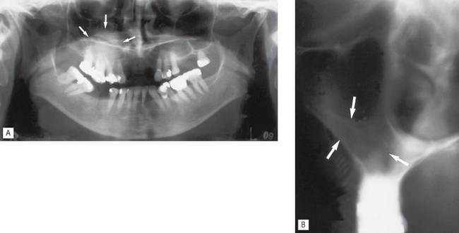
Fig. 16.10A Scanora® dental panoramic tomograph showing a poorly defined zone of opacity in the right maxilla (arrowed) in the area of the antrum. B Cross-sectional (transverse) tomographic image through the right maxilla showing the opacity to be caused by an increased bone thickness in the base of the antrum and lateral margin (arrowed). The patient had had previous surgery in this area.
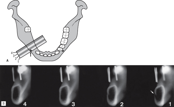
Fig. 16.11A Diagram showing the relationship between the mandible and one typical set of four cross-sectional (transverse) tomographic images. B An example of four 4-mm wide Scanora® spiral tomographic slices corresponding to the sections illustrated in diagram A. The mental canal is demonstrated clearly on slice (1) (arrowed). The vertical opaque metal markers in the localization stent are evident on all four slices.
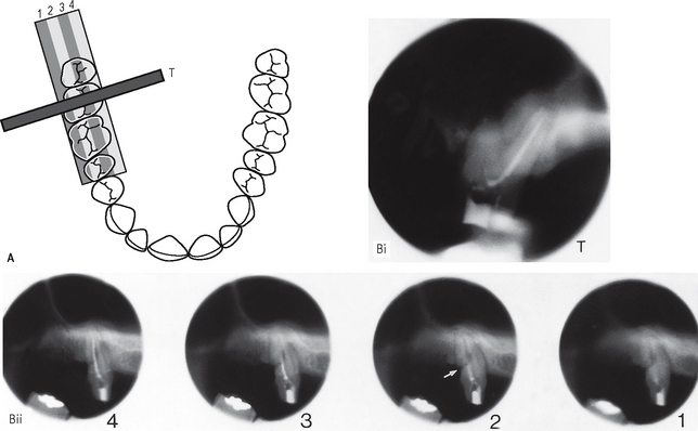
Fig. 16.12A Diagram of the maxillary arch showing the relationship between the right maxillary molar teeth and one set of four tangential tomographic images and one cross-sectional (transverse) image (T). B An example of Scanora® spiral tomographic slices corresponding to the various sections illustrated in diagram A, through the  (i) Cross-sectional or transverse slice (T) demonstrating the root filling in the palatal root canal. (ii) Four tangential slices. A fracture through the distobuccal root is demonstrated on slice (2) (arrowed).