Chapter 17 Panoramic radiography (dental panoramic tomography)
INTRODUCTION
Panoramic radiography or dental panoramic tomography has become a very popular technique in dentistry. The main reasons for this include:
• All the teeth and their supporting structures are shown on one image (see Fig. 17.1)
• The technique is relatively simple
• The radiation dose is relatively low, particularly with modern DC units and when using rare-earth intensifying screens or digital image receptors.
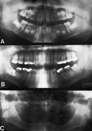
Fig. 17.1 Examples of dental panoramic radiographs. A A child in mixed dentition. B A dentate adult. C An edentulous adult.
The major drawback to the technique is that the resultant film is a sectional radiograph produced by moving equipment, and like all other forms of tomography (see Ch. 16) only structures within the section will be evident and in focus on the final film. In panoramic tomography, the section or focal trough is designed to be approximately horseshoe-shaped, corresponding to the shape of the dental arches. Image quality is generally inferior to that obtained using intra-oral radiographic techniques – irrespective of the type of image receptor used – and interpretation is more complicated.
SELECTION CRITERIA
In the UK, the 2004 Selection Criteria in Dental Radiography booklet recommends panoramic radiography in general practice in the following circumstances:
• Where a bony lesion or unerupted tooth is of a size or position that precludes its complete demonstration on intra-oral radiographs
• In the case of a grossly neglected mouth
• As part of an assessment of periodontal bone support where there is pocketing greater than 6mm
• For the assessment of wisdom teeth prior to planned surgical intervention. Routine radiography of unerupted third molars is not recommended
• As part of an orthodontic assessment where there is a clinical need to know the state of the dentition and the presence/absence of teeth. The use of clinical criteria to select patients rather than routine screening patients is essential.
In addition, in dental hospitals panoramic radiographs are also used to assess:
• Fractures of all parts of the mandible except the anterior region
• Antral disease — particularly to the floor, posterior and medial walls of the antra
• Destructive diseases of the articular surfaces of the TMJ
• Vertical alveolar bone height as part of pre-implant planning.
The 2004 Selection Criteria booklet specifically states that ‘panoramic radiographs should only be taken in the presence of specific clinical signs and symptoms’, and goes on to say that ‘there is no justification for review panoramic radiography at arbitrary intervals’ (see Ch. 8 on justification).
THEORY
The theory of dental panoramic tomography is complicated. Nevertheless, an understanding of how the resultant radiographic image is produced and which structures are in fact being imaged, is necessary for a critical evaluation, and for the interpretation of this type of radiograph.
The difficulty in panoramic tomography arises from the need to produce a final shape of focal trough which approximates to the shape of the dental arches.
An explanation of how this final horseshoe-shaped focal trough is achieved is given below. But first, other types of tomography — which form the basis of panoramic tomography — are described, showing how they result in different shapes of focal trough. These include:
• Linear tomography using a wide or broad X-ray beam
Broad-beam linear tomography
This was described in detail in Chapter 16 and is illustrated again in Figure 17.2. The synchronized movement of the tubehead and film, in the vertical plane, results in a straight linear focal trough. The broad X-ray beam exposes the entire film throughout the exposure.
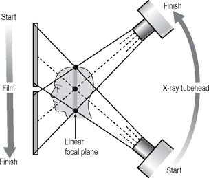
Fig. 17.2 Diagram showing the theory of broad-beam linear tomography to produce a vertical coronal section with the synchronized movement of the X-ray tubehead and the film in the vertical plane. Using a broad beam, there will be multiple centres of rotation (three are indicated: •), all of which will lie in the shaded zone. As all these centres of rotation will be in focus, this zone represents the focal plane or section that will appear in focus on the resultant tomograph. Note — the broad X-ray beam exposes the entire film throughout the exposure.
Slit or narrow-beam linear tomography
A similar straight linear tomograph can also be produced by modifying the equipment and using a narrow or slit X-ray beam. The equipment is designed so that the narrow beam traverses the film exposing different parts of the film during the tomographic movement. Only by the end of the tomographic movement has the entire film been exposed. The following equipment modifications are necessary:
• The X-ray beam has to be collimated from a broad beam to a narrow beam.
• The film cassette has to be placed behind a protective metal shield. A narrow opening in this shield is required to allow a small part of the film to be exposed to the X-ray beam at any one instant.
• A cassette carrier, incorporating the metal shield, has to be linked to the X-ray tubehead to ensure that they move in the opposite direction to one another during the exposure. This produces the synchronized tomographic movement in the vertical plane.
• Within this carrier, the film cassette itself has to be moved in the same direction as the tubehead. This ensures that a different part of the film is exposed to the X-ray beam throughout the exposure.
The principle of narrow-beam linear tomography using this equipment is illustrated in Figure 17.3.
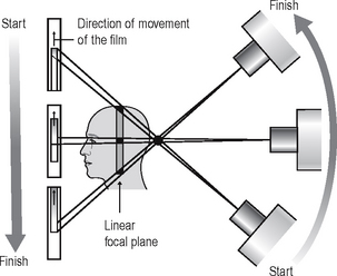
Fig. 17.3 Diagram showing the theory of narrow-beam linear tomography to produce a vertical coronal section. The tomographic movement is produced by the synchronized movement of the X-ray tubehead and the cassette carrier, in the vertical plane. The film, placed behind the metal protective front of the cassette carrier, also moves during the exposure, in the same direction as the X-ray tubehead. The narrow X-ray beam traverses the patient and film, exposing a different part of the film throughout the cycle.
Narrow-beam rotational tomography
In this type of tomography, narrow-beam equipment is again used, but the synchronized movement of the X-ray tubehead and the cassette carrier are designed to rotate in the horizontal plane, in a circular path around the head, with a single centre of rotation. The resultant focal trough is curved and forms the arc of a circle, as shown in Figure 17.4.
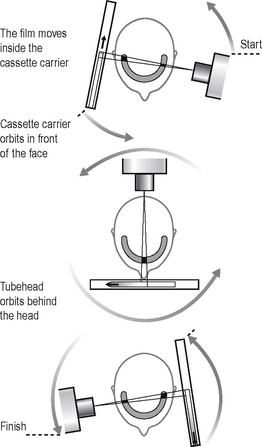
Fig. 17.4 Diagrams showing the theory of narrow beam rotational tomography. The tomographic movement is provided by the circular synchronized movement of the X-ray tubehead in one direction and the cassette carrier in the opposite direction, in the horizontal plane. The equipment has a single centre of rotation. The film also moves inside the cassette carrier so that a different part of the film is exposed to the narrow beam during the cycle, thus by the end the entire film has been exposed. The focal plane or trough (shaded) is curved and forms the arc of a circle.
Important points to note
• The X-ray tubehead orbits around the back of the head while the cassette carrier with the film orbits around the front of the face.
• The X-ray tubehead and the cassette carrier move in opposite directions to one another.
• The film moves in the same direction as the X-ray tubehead, behind the protective metal shield of the cassette carrier.
• A different part of the film is exposed to the X-ray beam at any one instant, as the equipment orbits the head.
• The simple circular rotational movement with a single centre of rotation produces a curved circular focal trough.
• As in conventional tomography, shadows of structures not within the focal trough will be out of focus and blurred owing to the tomographic movement.
DENTAL PANORAMIC TOMOGRAPHY
The dental arch, though curved, is not the shape of an arc of a circle. To produce the required elliptical, horseshoe-shaped focal trough, panoramic tomographic equipment employs the principle of narrow-beam rotational tomography, but uses two or more centres of rotation.
There are several dental panoramic units available; they all work on the same principle but differ in how the rotational movement is modified to image the elliptical dental arch. Four main methods (see Fig. 17.5) have been used including:
• Two stationary centres of rotation, using two separate circular arcs
• Three stationary centres of rotation, using three separate circular arcs
• A continually moving centre of rotation using multiple circular arcs combined to form a final elliptical shape
• A combination of three stationary centres of rotation and a moving centre of rotation.
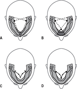
Fig. 17.5 Diagrams showing the main methods that have been used to produce a focal trough that approximates to the elliptical shape of the dental arch using different centres of rotation. A 2 stationary, B 3 stationary, C continually moving, D combination of 3 stationary and moving centre.
However the focal troughs are produced, it should be remembered that they are three-dimensional. The focal trough is thus sometimes described as a focal corridor. All structures within the corridor, including the mandibular and maxillary teeth, will be in focus on the final radiograph. The vertical height of the corridor is determined by the shape and height of the X-ray beam and the size of the film as shown in Figure 17.6.
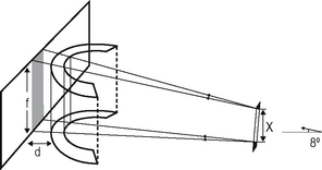
Fig. 17.6 Diagram showing how the height of the three-dimensional focal corridor is determined. The height (x) of the X-ray beam is collimated to just cover the height (f) of the film. The separation of the focal trough and the film (d), coupled with the 8° upward angulation of the X-ray beam results in the final image being slightly magnified.
As in other forms of narrow-beam tomography, a different part of the focal trough is imaged throughout the exposure. The final radiograph is thus built up of sections (see Fig. 17.7), each created separately, as the equipment orbits around the patient’s head.
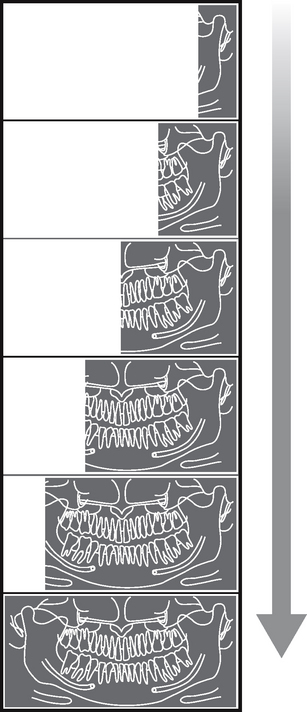
Fig. 17.7 Diagram showing the gradual build-up of a panoramic tomograph over an 18-second cycle, illustrating how a different part of the patient is imaged at different stages in the cycle.
Equipment
There are several different panoramic units available. Although varying in design and apperance all consist of four main components, namely:
• An X-ray tubehead, producing a narrow fan-shaped X-ray beam, angled upwards at approximately 8° to the horizontal (see Fig. 17.6)
• Control panel (see Fig. 17.9)
• Patient-positioning apparatus including chin and temporal supports and light beam markers
• An image receptor (film or digital) with or without an associated carriage assembly.
Traditional panoramic equipment was designed to use indirect-action radiographic film in an extra-oral cassette as the image receptor. With the advent of digital imaging several variations in image receptor now exist, including:
• Cassettes containing indirect-action film and rare-earth intensifying screens
• Cassettes containing a digital phosphor plate
• Flat cassette-sized solid-state sensors designed to fit into existing equipment
• Specially designed solid-state sensors—an integral part of new equipment (see Ch. 6).
Examples of two typical machines are shown in Figure 17.8. The regulations relating to the technical aspects of panoramic equipment are summarized in Chapter 8.
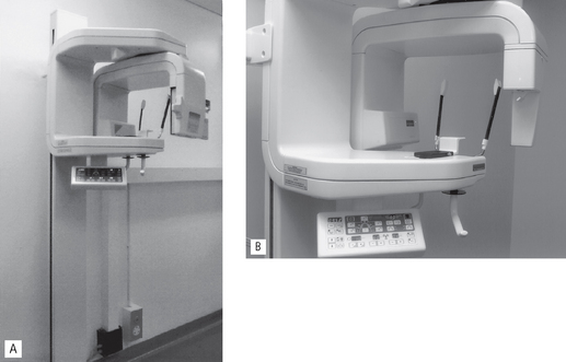
Fig. 17.8 Examples of two different types of Planmeca panoramic radiography machines. A Traditional unit incorporating a cassette suitable for film-based or digital phosphor plate imaging. B Dedicated digital unit with specifically designed built-in solid-state digital sensor. The basic components including the X-ray tubehead, the control panel and the patient positioning apparatus are common to both units.
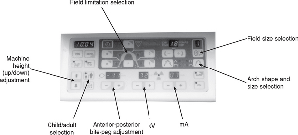
Control panel
The control panel design also varies from one machine to another but a typical panel is shown in Figure 17.9. The main features usually allow the operator to:
Equipment movement
A diagrammatic example of how a typical panoramic machine, using film or digital phosphor plate as the image receptor, functions is shown in Figure 17.10.
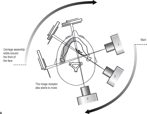
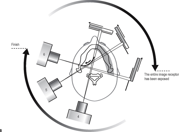
Fig. 17.10A Diagram from above, showing the relative movements of the X-ray tubehead, carriage assembly and image receptor (film or phosphor plate) during the first half of the panoramic cycle when the left side of the jaw is imaged. As the X-ray tubehead moves behind the patient’s head to image the anterior teeth, the carriage assembly moves in front of the patient’s face and the centre of rotation moves forward along the dark arc (arrowed) towards the midline. Note that the X-ray beam has to pass through the cervical spine. Diagram from above, showing the relative movements during the second half of the panoramic cycle when the right side of the jaw is imaged. The X-ray tubehead and carriage assembly continue to move around the patient’s head to image the opposite side, and the centre of rotation moves backwards along the dark arc (arrowed) a way from the midline. Throughout the cycle the film or phosphor plate is also continuously moving as illustrated, so that a different part of the image receptor is exposed at any one time.
Technique and positioning
The exact positioning techniques vary from one machine to another. However, there are some general requirements that are common to all machines and these can be summarized as follows:
Equipment preparation
• The cassette containing the film or phosphor plate should be inserted into carriage assembly (if appropriate).
• The operator should put on suitable protective gloves (e.g. latex or nitrile) (see Ch. 9).
• The collimation should be set to the size of field required.
• The appropriate exposure factors should be selected according to the size of the patient—typically in range 70–100 kV and 4–12 mA.
Patient positioning
• The patient should be positioned in the unit so that their spine is straight and instructed to hold any stabilizing supports or handles provided (see Fig. 17.11).
• The patient should be instructed to bite their upper and lower incisors edge-to-edge on the bite-peg with their chin in good contact with the chin support.
• The head should be immobilized using the temple supports.
• The light beam markers should be used so that the mid-sagittal plane is vertical, the Frankfort plane is horizontal and the canine light lies between the upper lateral incisor and canine.
• The patient should be instructed to close their lips and press their tongue on the roof of their mouth so that it is in contact with their hard palate and not to move throughout the exposure cycle (approximately 15–18 seconds).
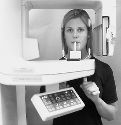
Fig. 17.11 Patient positioned in the Planmeca PM2002, Note the bite-peg, chin and temple supports and the three light-beam markers to facilitate accurate positioning.
Important points to note
• Panoramic radiography is generally considered to be unsuitable for children under six years old, because of the length of the exposure and the need for the patient to keep still.
• A protective lead apron should not be used. In the UK the 2001 Guidance Notes confirm that there is no justification for using a protective lead apron. If used, it can interfere with the final image (see Fig. 17.23F).
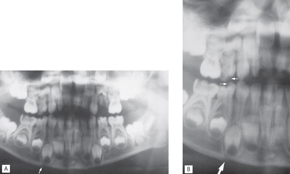
Fig. 17.23 A Panoramic radiograph of a young child, who had fallen over, showing a step deformity (arrowed) in the lower border suggesting a fracture. B Same radiograph enlarged showing the step deformity (large arrow), but also notice the step deformities in the crowns of the upper and lower first deciduous molars (small arrows). Sudden slight vertical movement of the patient makes interpretation difficult.
After exposure
• The temple supports should release automatically to enable the patient to leave the machine.
• The equipment should be wiped down with a surface disinfectant and the bite-peg sterilized (see Ch. 9).
The importance of accurate patient positioning
The positioning of the patient’s head within this type of equipment is critical — it must be positioned accurately so that the teeth lie within the focal trough. The effects of placing the head too far forward, too far back or asymmetrically in relation to the focal trough, are shown in Figure 17.12. The parts of the jaws outside the focal trough will be out of focus. The fan-shaped X-ray beam causes patient malposition to be represented mainly as distortion in the horizontal plane, i.e. teeth appear too wide or too narrow rather than foreshortened or elongated. Thus, if the patient is rotated to the left (as shown in Fig. 17.12C), the left teeth are nearer the film and will be narrower, while the teeth on the right will be further away from the film and wider. These and other positioning errors are shown later (see Fig. 17.24).
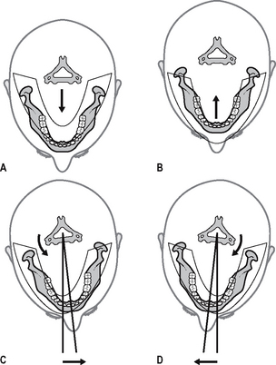
Fig. 17.12 Diagrams showing the position of the mandible in relation to the focal trough when the patient is not positioned correctly. A The patient is too close to the film and in front of the focal trough. B The patient is too far away from the film and behind the focal trough. C and D The patient is placed asymmetrically within the machine.
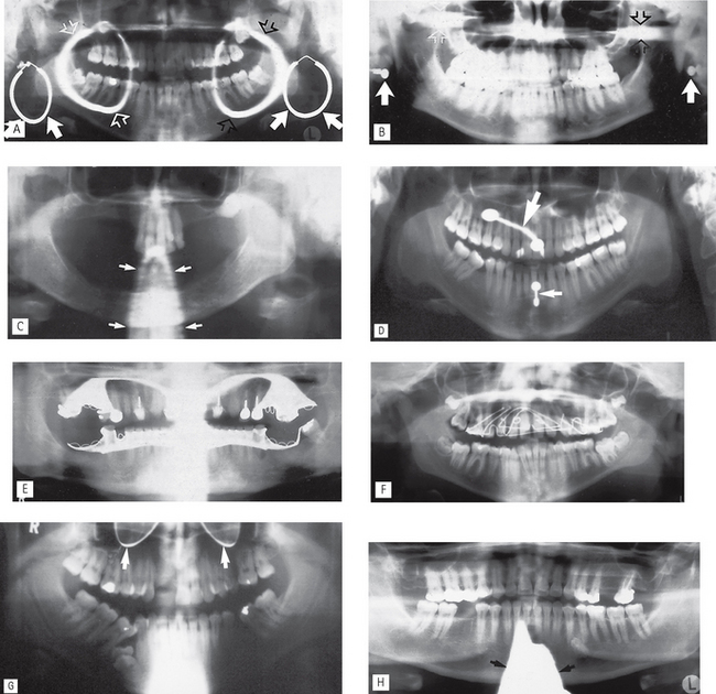
Fig. 17.24 Examples of common patient preparation errors.
A Failure to remove large ring-shaped earrings — note each earring casts two shadows, one real (in focus, solid arrows) and one ghost (blurred, open arrows). The ghost shadow of the LEFT earring is marked with white open arrows, that of the RIGHT earring with black open arrows.
B Failure to remove stud earring, real shadows (solid arrows) with ghost shadows (open arrows).
C Failure to remove a necklace — blurred ghost shadow (arrowed).
D Failure to remove piercing in the tongue (large arrow) and lower lip (small arrow).
E Failure to remove upper and lower metallic partial dentures.
F Failure to remove an upper orthodontic appliance.
G Failure to remove spectacles (arrowed).
H Inappropriate use of a protective lead apron — too high on the neck casting a dense radiopaque shadow (arrowed) over the anterior part of the mandible.
However accurately the patient’s head is positioned, the inclination of the incisor teeth, or the underlying skeletal base pattern, may make it impossible to position both the mandibular and maxillary teeth ideally within the focal corridor (see Fig. 17.13).
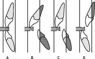
Fig. 17.13 Diagrams showing the vertical walls of the focal trough in the incisor region and the relative positions of the teeth with different underlying dental or skeletal abnormalities. A Class I. B Gross class II division 1 malocclusion with large overjet. C Angle’s class II skeletal base. D Angle’s class III skeletal base. The shaded areas outside the focal trough will be blurred and out of focus.
Technique variations
There are a number of technique variations possible with modern equipment, including:
• Edentulous patient positioning — the chin support is used instead of the bite-peg and the canine positioning light beam is centred on the corner of the mouth.
• TMJ programmes — (see Ch. 31).
• Cross-sectional imaging for implant assessment (see Ch. 24).
• Collimation — restricting the size of the beam so restricting the field of view e.g. the height of the beam is automatically reduced when selecting the settings for children.
• Field limitation techniques — only preselected parts of the patient are exposed and imaged on the final film as illustrated in Figure 17.14.
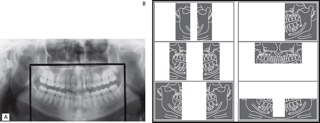
Fig. 17.14A The effect of selecting collimation to reduce the height of the beam and field limitation techniques to exclude the rami and parotid producing the so-called dentition only image. This has been reported to reduce the effective dose by approximately 50%. B Diagram showing a selection of images that can be obtained by using collimation and field limitation techniques.
Normal anatomy
The normal anatomical shadows that are evident on panoramic radiographs vary fromone machine to another, but in general they can be subdivided into:
• Real or actual shadows of structures in, or close to, the focal trough
• Ghost or artefactual shadows created by the tomographic movement and cast by structures on the opposite side or a long way from the focal trough. The 8° upward angulation of the X-ray beam means that these ghost shadows appear at a higher level than the structures that have caused them.
These two types of shadows are clearly demonstrated in Figures 17.17 and 17.18.
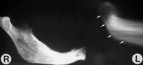
Fig. 17.17 Panoramic radiograph taken of the right half of a hemisectioned mandible. The real shadows are clearly shown on the right. The ghost shadow of the mandible is shown on the left (arrowed). Note these ghost shadows are at a higher level on the film than the real shadows because of the 8° rising X-ray beam that is used
(kindly provided by Dr N. Drage).
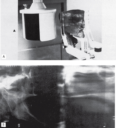
Fig. 17.18 Hemisected cadaver head positioned in a dental panoramic machine. B Resultant radiograph showing the real hard and soft tissue shadows on the right and the ghost shadows on the left.
(Reproduced from Oral Radiology, by kind permission of Paul W. Goaz and Stuart C. White and The C.V. Mosby Company.)
Real or actual shadows
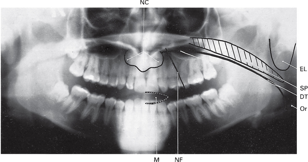
Important hard tissue shadows (see Fig. 17.15)
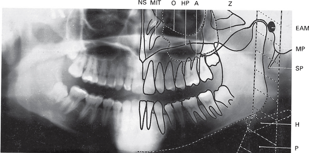
Fig. 17.15 A dental panoramic tomograph showing the main real hard tissue shadows, including the plastic head support, drawn in on one side of the radiograph, NS — nasal septum, MIT — middle and inferior turbinates, O — orbital margin, HP — hard palate, A — floor of antrum, Z — zygomatic arch, EAM — external auditory meatus, MP — mastoid process, SP — styloid process, H — hyoid, P — plastic head support.
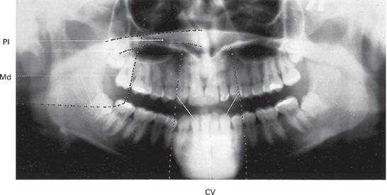
Ghost or artefactual shadows (see Fig. 17.19)
Advantages and disadvantages
Advantages
• A large area is imaged and all the tissues within the focal trough are displayed, including the anterior teeth, even when the patient is unable to open the mouth.
• The image is easy for patients to understand, and is therefore a useful teaching aid.
• Patient movement in the vertical plane distorts only that part of the image being produced at that instant.
• Positioning is relatively simple and minimal expertise is required.
• The overall view of the jaws allows rapid assessment of any underlying, possibly unsuspected, disease.
• The view of both sides of the mandible on one film is useful when assessing fracures and is comfortable for the injured patient.
• The overall view is useful for evaluation of periodontal status and in orthodontic assessments.
• The antral floor, medial and posterior walls are well shown.
• Both condylar heads are shown on one film, allowing easy comparison (see Ch. 31).
• The radiation dose (effective dose) is about one-fifth of the dose from a full-mouth survey of intra-oral films (see Ch. 3).
• Development of field limitation techniques which result in further dose reduction.
Disadvantages
• The tomographic image represents only a section of the patient. Structures or abnormalities not in the focal trough may not be evident (Fig. 17.20).
• Soft tissue and air shadows can overlie the required hard tissue structures (Fig. 17.21).
• Ghost or artefactual shadows can overlie the structures in the focal trough (Fig. 17.22).
• The tomographic movement together with the distance between the focal trough and film produce distortion and magnification of the final image (approx. × 1.3).
• The use of indirect-action film and intensifying screens results in some loss of image quality but image resolution can be improved by using digital image receptors.
• The technique is not suitable for children under six years or on some disabled patients because of the length of the exposure cycle.
• Some patients do not conform to the shape of the focal trough and some structures will be out of focus.
• Movement of the patient during the exposure can create difficulties in image interpretation (Fig. 17.23).
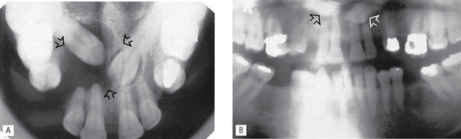
Fig. 17.20A Upper standard occlusal showing unerupted  and a large dentigerous cyst (arrowed) associated with
  . B Dental panoramic radiograph showing the two unerupted canines out of focus (arrowed) and only a suggestion of the dentigerous cyst, because they are all outside the focal trough.
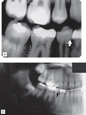
 (arrowed). B Dental panoramic radiograph showing an apparent lesion in this tooth (arrowed). This appearance is created by the overlying air shadow of the corner of the mouth.
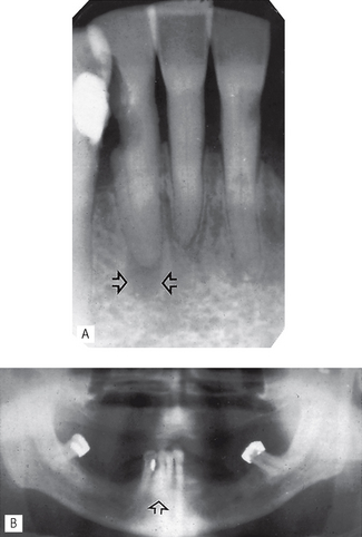
 region showing an area of radiolucency at the apex of
  (arrowed). B Dental panoramic radiograph showing no evidence of the lesion (arrowed) owing to superimposition of the shadow of the cervical vertebrae.
Assessment of image quality
As mentioned in previous chapters, in relation to all other radiographs, image quality assessment essentially involves three separate stages, namely:
• Comparison of the image against ideal quality criteria
• Subjective rating of image quality using published standards
• Detailed assessment of rejected films to determine the source of error.
Ideal quality criteria
Irrespective of the type of image receptor being used, typical quality criteria for a full field of view panoramic radiograph include:
• All the upper and lower teeth and their supporting alveolar bone should be clearly demonstrated
• The whole of the mandible should be included
• Magnification in the vertical and horizontal planes should be equal
• The right and left molar teeth should be equal in their mesiodistal dimension
• The density across the image should be uniform with no air shadow above the tongue creating a radiolucent (black) band over the roots of the upper teeth
• The image of the hard palate should appear above the apices of the upper teeth
• Only the slightest ghost shadows of the contralateral angle of the mandible and the cervical spine should be evident
• There should be no evidence of artefactual shadows due to dentures, earrings and other jewellery
• The patient identification label should not obscure any of the above features
• The image should be clearly labelled with the patient’s name and date of the examination
• The image should be clearly marked with a Right and/or Left letter.
Subjective rating of image quality
The simple three-point subjective rating scale published in the 2001 Guidance Notes was introduced in Chapter 10 and is discussed in detail, together with the errors associated with exposure factors and chemical processing, in Chapter 18. The summary is shown again in Table 17.1. Panoramic patient preparation and positioning errors are described below.
Table 17.1 Subjective quality rating criteria for film-captured images published in the 2001 Guidance Notes for Dental Practitioners on the Safe Use of X-ray equipment
| Rating | Quality | Basis |
|---|---|---|
| 1 | Excellent | No errors of patient preparation, exposure, positioning, processing or film handling |
| 2 | Diagnostically acceptable | Some errors of patient preparation, exposure, positioning, processing or film handling, but which do not detract from the diagnostic utility of the radiograph |
| 3 | Unacceptabe | Errors of patient preparation, exposure, positioning, processing or film handling, which render the radiograph diagnostically unacceptable |
Assessment of rejected films and determination of errors
Patient preparation errors (Fig. 17.24)
Patient positioning errors (Figs 17.25 and 17.26)
• Failure to ensure that the spine is straight (ghosting shadow error)
• Failure to ensure the incisors are biting edge-to-edge on the bite-peg (anteroposterior error)
• Failure to use the light beam marker to ensure midsagittaal plane is vertical and the head is not rotated (horizontal error)
• Failure to use the light beam marker to ensure the Frankfort plane is horizontal (vertical error)
• Failure to instruct the patient to press the tongue against the roof of the mouth (air shadow error)
• Failure to instruct the patient to remain still throughout the exposure (movement error).
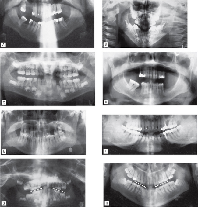
Fig. 17.25 Examples of common patient positioning errors. A Failure to position the neck correctly — extension of the neck causing excessive spinal ghosting shadows over the anterior teeth. B Anteroposterior error — patient positioned too far forwards (too close to the image receptor) and vertical error — Frankfort plane not horizontal (chin tipped down) creating narrow, out of focus anterior teeth, distorted occlusal plane (so-called smiley face) and excessive peripheral spinal shadowing. C Anteroposterior error — patient positioned too far back (too far away from the image receptor) creating widened, magnified and out of focus anterior teeth. D Anteroposterior error — patient positioned too far forwards (too close to the image receptor) creating narrowed incisors and failure to instruct patient to keep their tongue in contact with the palate creating the radiolucent band across the film. E Horizontal error — patient asymmetrical, rotated to the RIGHT. The RIGHT molars are closer to the image receptor and smaller, the LEFT molars are further away from the image receptor and larger. F Vertical error — Frankfort plane not horizontal (chin tipped down) creating out of focus lower incisors and excessive ghosting shadows of the contralateral angles of the mandible. G Vertical error — Frankfort plane not horizontal (chin tipped up) creating out-of-focus upper incisors and distorted occlusal plane (arrowed) (so-called grumpy face). H Vertical error — Frankfort plane not horizontal (chin tipped down) creating out of focus lower incisors and distorted occlusal plane (arrowed) (so-called smiley face).
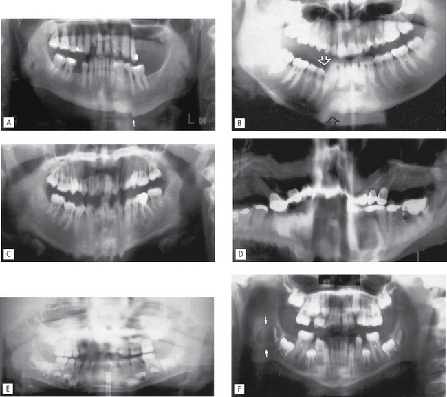
Fig. 17.26 Examples of failure to instruct the patient to keep still during the full panoramic cycle.
A Sudden movement in the vertical plane — distortion of the image 45 region creating a step-deformity in the lower border (see also Fig. 17.23).
B Movement in the vertical plane caused by the patient opening their mouth causing distortion in the  region (arrowed).
C Multiple vertical movements while the anterior teeth were being imaged.
D Continuous shaking movements throughout the cycle.
E Sudden side-to-side horizontal movement while the anterior teeth were being imaged causing them to be blurred.
F Horizontal movement towards the end of the cycle causing horizontal elongation and stretching of the shadow of the developing lower right third molar (arrowed).
Equipment positioning errors (Fig. 17.27)
• Failure to set height adjustment correctly
• Failure to select correct exposure settings (see Ch. 18)
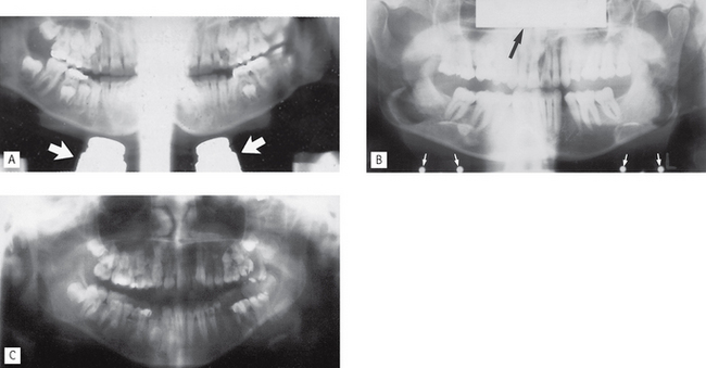
Fig. 17.27 Examples of equipment positioning errors.
A The X-ray tubehead and image receptor carriage assembly positioned too low relative to the patient—the antra and condyles are not imaged but shadows of the chin rest are evident (arrowed).
B Cassette positioned back-to-front in the carriage assembly. Name plate and hinge screws are evident (arrowed).
Footnote
Dental panoramic radiographs should not be considered an alternative to high-resolution intra-oral radiographs. However, they are commonly considered as an alternative to right and left oblique lateral radiographs or the bimolar projection (see Ch. 13) mainly because it is assumed that less operator expertise is required to produce panoramic images of adequate diagnostic quality. Unfortunately, the multiple and varied causes of error in panoramic radiography make the technique very operator-dependent, no matter how sophisticated the equipment and the image receptors become. The use of digital sensors (solid-state or phosphor plate) improves the resolution of panoramic images when compared to those captured using indirect-action film and intensifying screen combinations. In addition, digital images can be enhanced and manipulated using computer software (see Ch. 7).
The diagnostic value of all panoramic images is increased considerably if clinicians understand that the image created is a tomograph (whatever the image receptor) and are aware of the limitations that this imposes. A suggested systematic approach to interpretation of panoramic images is outlined in Chapter 20.