Computed Radiography
At the completion of this chapter, the student should be able to do the following:
1 Describe several advantages of computed radiography over screen-film radiography.
2 Identify workflow changes when computed radiography replaces screen-film radiography.
3 Discuss the relevant features of a storage phosphor imaging plate.
4 Explain the operating characteristics of a computed radiography reader.
5 Discuss spatial resolution, contrast resolution, and noise related to computed radiography.
6 Identify opportunities for patient radiation dose reduction with computed radiography.
PRESENTLY, AN acceleration in the conversion from screen-film radiography (analog) to digital radiography (DR) is occurring. Digital imaging began with computed tomography (CT) and magnetic resonance imaging (MRI).
Digital radiography was introduced in 1981 by Fuji with the first commercial computed radiography (CR) imaging system. After many improvements that were made over the next decade, CR became clinically acceptable and today enjoys widespread use.
Today, medical imaging is complemented by multiple forms of DR in addition to CR. At this time, CR is the most widely used DR modality, and although other DR systems are increasingly in use, it seems there will always be a need for CR because of its unique properties.
This chapter discusses CR, but readers should understand that much of the information relevant to CR applies also to DR because CR is a form of DR.
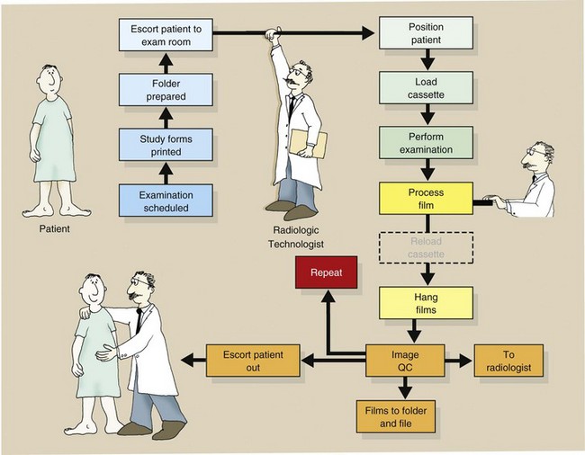
Before computed radiography (CR) is discussed, a review of the workload steps associated with screen-film radiography is in order. Consider the sequence outlined in Figure 15-1.
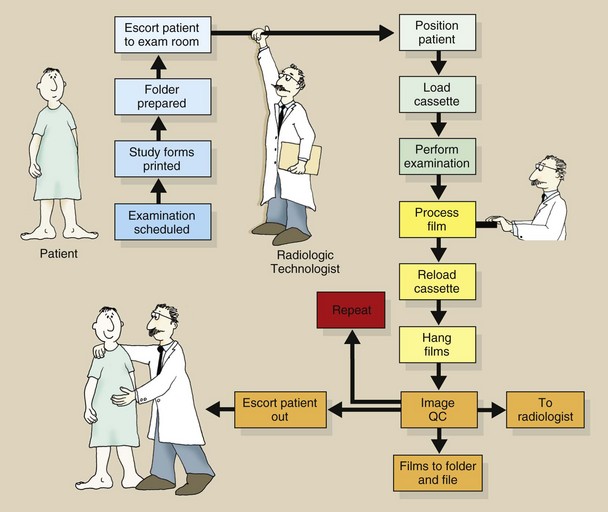
To conduct a screen-film radiographic examination, one should first produce a paper trail of the study, process the image with wet chemistry, and finally physically file the image after accepting that it is diagnostic. CR imaging eliminates some of these steps and can produce better medical images at lower patient dose.
The Computed Radiography Image Receptor
Many similarities have been observed between screen-film imaging and CR imaging. Both modalities use as the image receptor an x-ray sensitive plate that is encased in a protective cassette. The two techniques can be used interchangeably with any x-ray imaging system. Both produce a latent image, albeit in a different form, that must be made visible via processing.
Here, however, the similarities stop. In screen-film radiography, the radiographic intensifying screen is a scintillator that emits light in response to an x-ray interaction. In CR, the response to x-ray interaction is seen as trapped electrons in a higher energy metastable state.
Photostimulable Luminescence
Some materials such as barium fluorohalide with europium (BaFBr : Eu or BaFI : Eu) emit some light promptly in the way that a scintillator does following x-ray exposure. However, they also emit light some time later when exposed to a different light source. Such a process is called photostimulable luminescence (PSL).
The europium (Eu) is present in only very small amounts. It is an activator and is responsible for the storage property of the PSL. The activator is similar to the sensitivity center of a film emulsion because without it, there would be no latent image.
 In the same way that the photographic effect is not fully understood and continues to be studied, so too the physics of PSL is not fully understood.
The atoms of barium fluorobromide have atomic numbers of 56, 9, and 35, respectively, with K-shell electron binding energies of 37, 5, and 12 keV, respectively. Many Compton and photoelectric x-ray interactions occur with outer-shell electrons, sending them into an excited, metastable state (Figure 15-2). When these electrons return to the ground state, visible light is emitted (Figure 15-3).
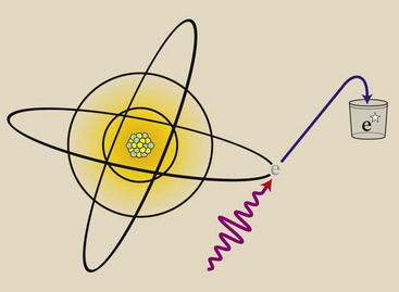
FIGURE 15-2 X-ray interaction with a photostimulable phosphor results in excitation of electrons into a metastable state.
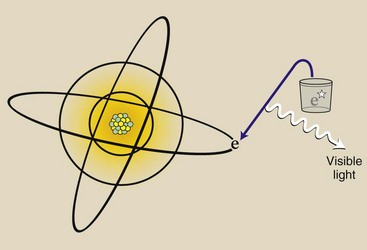
Over time, these metastable electrons return to the ground state on their own. However, this return to the ground state can be accelerated or stimulated by exposing the phosphor to intense infrared light from a laser—hence the term photostimulable luminescence from a photostimulable phosphor (PSP).
The PSP, barium fluorohalide, is fashioned similarly to a radiographic intensifying screen, as is shown in Figure 15-4. Because the latent image occurs in the form of metastable electrons, such screens are called storage phosphor screens (SPSs).
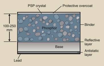
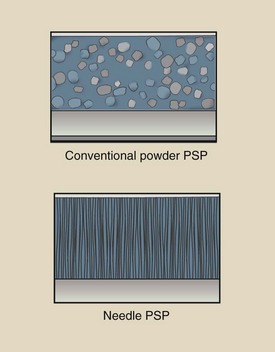
The SPS appears white because the small PSP particles (3–10 µm) scatter light excessively. Such a scattering is called turbid. PSP particles are randomly positioned throughout a binder.
SPSs are mechanically stable, electrostatically protected, and fashioned to optimize the intensity of stimulated light. Some SPSs incorporate phosphors grown as linear filaments (Figure 15-5) that enhance the absorption of x-rays and limit the spread of stimulated emission.
Imaging Plate
The PSP screen is housed in a rugged cassette that appears similar to a screen-film cassette (Figure 15-6). In this form as an image receptor, the PSP screen-film cassette is called an imaging plate (IP).
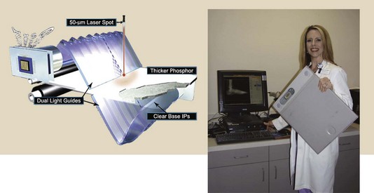
FIGURE 15-6 Computed radiography imaging plate prepared for insertion into electronic reader. (Courtesy Melanie Hail, Lone Star College System and Fuji Medical Systems.)
The IP is handled in the same manner as a screen-film cassette; in fact, this is a principal advantage of CR. CR can be substituted for screen-film radiography and used with any x-ray imaging system. The PSP screen of the IP is not loaded and unloaded in a darkroom. Rather, it is handled in the manner of a screen-film daylight loader.
The IP has lead backing that reduces backscatter x-rays. This improves the contrast resolution of the image receptor.
Light Stimulation–Emission
Thermoluminescent dosimetry (TLD) and optically stimulated luminescence (OSL) are the main radiation detectors used for occupational radiation monitoring (see Chapter 38). Light is emitted when a TLD crystal is heated. Light is emitted when an OSL crystal is illuminated. PSL is similar to OSL.
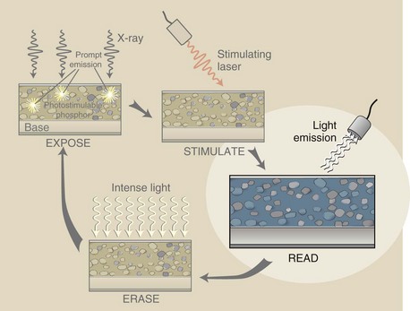
The sequence of events engaged in producing a PSL signal begins as shown in Figure 15-7. When an x-ray beam exposes a PSP, the energy transfer results in excitation of electrons into a metastable state. Approximately 50% of these electrons return to their ground state immediately, resulting in prompt emission of light.
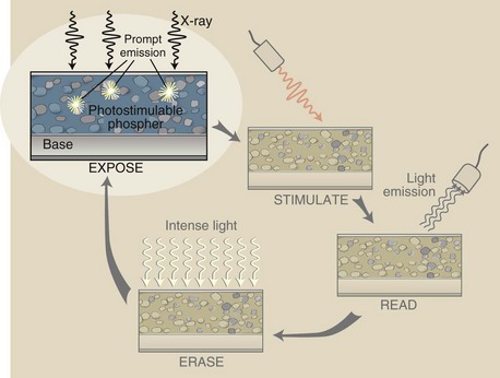
FIGURE 15-7 Expose: The first of a sequence of events that results in an x-ray–induced image-forming signal.
The remaining metastable electrons return to the ground state over time. This causes the latent image to fade and requires that the IP must be read soon after exposure. CR signal loss is objectionable after approximately 8 hours.
The next step in CR imaging is stimulation (Figure 15-8). The finely focused beam of infrared light with a beam diameter of 50 to 100 µm is directed at the PSP. As laser beam intensity increases, so does the intensity of the emitted signal.
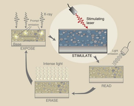
FIGURE 15-8 Stimulate: Stimulation of the latent image results from the interaction of an infrared laser beam with the photostimulable phosphor (PSP).
Note that as the laser beam penetrates, it spreads. The amount of spread increases with PSP thickness.
Figure 15-9 illustrates the third step in this imaging process, which is detecting (reading) the stimulated emission. The laser beam causes metastable electrons to return to the ground state with the emission of a shorter wavelength light in the blue region of the visible spectrum. Through this process, the latent image is made visible.
Some signal is lost as the result of (1) scattering of the emitted light and (2) the collection efficiency of the photodetector. Photodiodes (PDs) are the light detectors of choice for CR.
The final stage in PSL signal production is shown in Figure 15-10. The stimulation cycle of PSL signal acquisition does not completely transition all metastable electrons to the ground state. Some excited electrons remain.
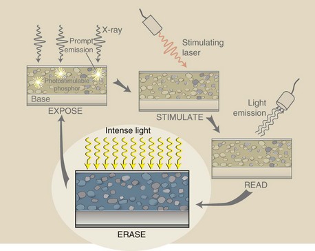
FIGURE 15-10 Erase: Before reuse, any residual metastable electrons are moved to the ground state by an intense light.
If residual latent image remained, ghosting could appear on subsequent use of the IP. Any residual latent image is removed by flooding the phosphor with very intense white light from a bank of specially designed fluorescent lamps.
The stimulation portion of PSP processing would result in no latent image if the laser beam were made to dwell longer at each position on the PSP, but this would require an unacceptable processing time.
The PSP is sufficiently sensitive that it can become fogged by background radiation.
The laser light used to stimulate the PSP is monochromatic, as can be seen in Figure 15-11. A HeNe gas laser used to be the stimulating source of choice, but this has been largely replaced by a solid state laser.
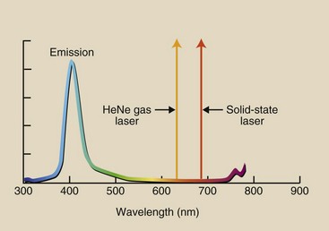
FIGURE 15-11 The laser light used to stimulate the photostimulable phosphor is monochromatic. Resultant emitted light is polychromatic.
The resulting emission has a polychromatic spectrum. The emitted light intensity is many orders of magnitude lower than that of the stimulating light; this poses additional challenges to the entire process.
Solid-state lasers produce longer wavelength light and therefore are less likely to interfere with emitted light. Even so, optical filters are necessary to allow only emitted light to reach the photodetector while blocking the intense stimulated light.
The Computed Radiography Reader
A commercial CR reader, as is shown in Figure 15-12, could be mistaken for a daylight film processor. However, a daylight film processor is based on wet chemistry processing. The CR reader represents the marriage of mechanical, optical, and computer modules.
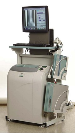
FIGURE 15-12 The computed radiography reader is a compact mechanical, optical, computer assembly. (Courtesy Carestream Health, Inc.)
Mechanical Features
When the CR cassette is inserted into the CR reader, the IP is removed and is fitted to a precision drive mechanism. This drive mechanism moves the IP constantly yet slowly (“slow scan”) along the long axis of the IP. Small fluctuations in velocity can result in banding artifacts, so the motor drive must be absolutely constant.
While the IP is being transported in the slow scan direction, a deflection device such as a rotating polygon (shown in Figure 15-13) or an oscillating mirror deflects the laser beam back and forth across the IP. This is the fast scan mode.
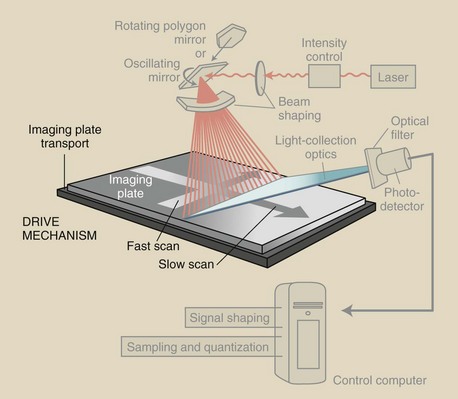
FIGURE 15-13 The drive mechanisms of the computed radiography (CR) reader move the imaging plate (IP) slowly along its long axis, while an oscillating beam deflection mirror causes the stimulating laser beam to sweep rapidly across the IP.
These drive mechanisms are coupled so the laser beam is blanked during retrace, similar to the situation described in Chapter 25 for a video monitor. The error tolerance for this mechanism is fractions of a pixel. Image edges from a CR reader that is out of tolerance appear “wavy.”
Another method is for the cassette to be placed in the reader vertically with the IP withdrawn downward. As this occurs, the cassette is scanned by a horizontal laser.
The IP barely leaves the cassette, so it is not subject to roller damage. Furthermore, the scan is nearly always located at right angles to the direction of any grid lines; in this way, aliasing artifacts are reduced.
Optical Features
The challenge to the CR reader is to precisely interrogate each metastable electron of the latent image in a precise fashion. Components of the optical subsystem include the laser, beam-shaping optics, light-collecting optics, optical filters, and a photodetector. These components are shown in Figure 15-14.
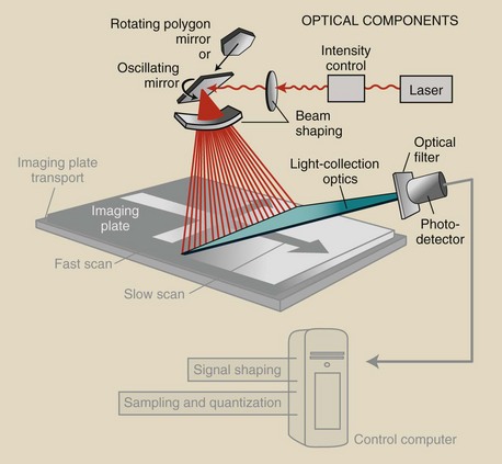
FIGURE 15-14 The optical components and optical path of a computed radiography (CR) reader are highlighted.
The laser is the source of stimulating light; however, it spreads as it travels to the rotating or oscillating reflector. This light beam is focused onto the reflector by a lens system that keeps the beam diameter small (<100 µm).
As the laser beam is deflected across the IP, it changes size and shape. Special beam-shaping optics keeps constant the beam size, shape, speed, and intensity.
A simple flashlight exercise can be used to explain what is needed for beam shaping. Shine a flashlight perpendicularly on a wall, and what do you see? A circle of light.
Now move the beam along the wall slowly but with constant velocity, and what do you see? The beam becomes distorted, moves faster, and is less intense. These types of changes in a CR reader are corrected with the use of beam-shaping optics.
Emitted light from the IP is channeled into a funnel-like fiber optic collection assembly and is directed at the photodetector, PMT, PD, or charge-coupled device (CCD). Before photodetection occurs, the light is filtered so that none of the long-wavelength stimulation light reaches the photodetector and swamps emitted light. In this case, emitted light is the signal and stimulating light the noise; therefore, proper filtering improves the signal-to-noise ratio.
Computer Control
The output of the photodetector is a time-varying analog signal that is transmitted to a computer system that has multiple functions (Figure 15-15).
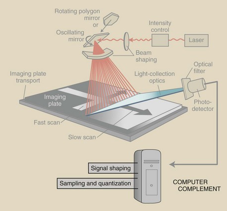
FIGURE 15-15 The computer complement to a computed radiography (CR) reader provides signal amplification, signal compression, scanning control, analog-to-digital conversion, and image buffering.
The time-varying analog signal from the photodetector is processed for amplitude, scale, and compression. This shapes the signal before the final image is formed. Then the analog signal is digitized, with attention paid to proper sampling (time between samples) and quantization (the value of each sample).
The image buffer is usually a hard disc. This is the place where a completed image can be stored temporarily until it is transferred to a workstation for interpretation or to an archival computer.
The computer of the CR reader is in control of the slow scan and the fast scan. This control works off the computer clock in gigahertz (GHz).
Imaging Characteristics
Medical imaging with CR is not much different from that with screen-film imaging. A cassette is exposed with an existing x-ray imaging system to form a latent image. The cassette is inserted into an automatic processor (reader), and the latent image is made visible.
Here the similarity ends. The four principal characteristics of any medical image are spatial resolution, contrast resolution, noise, and artifacts. Such characteristics are different for all digital radiography (DR), including CR from screen-film imaging. These are discussed in greater depth in later chapters.
Image Receptor Response Function
The shape of the characteristic curve for screen-film imaging is described in detail in Chapter 10. It is presented again in Figure 15-16 along with the “characteristic curve” for a CR image receptor. In CR and DR, it is not really a characteristic curve but rather an image receptor response function.
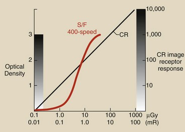
FIGURE 15-16 The image receptor response for computed radiography (CR) is shown with the characteristic curve of a screen-film image receptor.
Figure 15-16 suggests several differences between CR and screen-film image receptors. The response of screen-film extends through an optical density (OD) range from 0 to 3 because OD is a logarithmic function that represents three orders of magnitude, or 1000.
However, the screen-film image can display only approximately 30 shades of gray on a viewbox. That is why radiographic technique is so critical in screen-film imaging. Most screen-film imaging techniques aim for radiation exposure on the toe side of the characteristic curve.
Computed radiography imaging is characterized by extremely wide latitude. Four decades of radiation exposure results in 10,000 gray levels, each of which can be evaluated visually by postprocessing.
Proper radiographic technique and exposure are essential for screen-film radiography. Overexposure and underexposure result in unacceptable images (Figure 15-17).
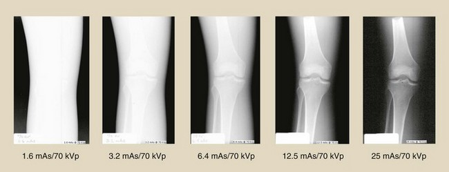
FIGURE 15-17 Improper radiographic technique with a screen-film image receptor results in an unacceptable image. (Courtesy Betsy Shields, Presbyterian Hospital, Charlotte, North Carolina.)
With CR, radiographic technique is not so critical because contrast does not change over 4 decades of radiation exposure. Figure 15-18 shows the appearance of CR images acquired with the same radiographic technique range as those used for Figure 15-17.
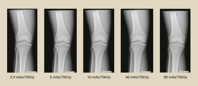
FIGURE 15-18 Computed radiography (CR) images obtained through the same radiographic technique used in Figure 15-17. (Courtesy Betsy Shields, Presbyterian Hospital, Charlotte, North Carolina.)
Image Noise
The principal source of noise on a radiographic image is scatter radiation; this is the same whether screen-film or CR image receptors are used. Box 15-1 reviews sources of noise in screen-film radiography.
Image noise associated with CR includes all sources listed in Box 15-1, plus those provided in Box 15-2. Each of the three subsystems of CR contributes noise to the image.
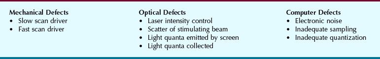
Fortunately, CR noise sources are bothersome only at very low image receptor radiation exposure. Newer CR systems have lower noise levels and therefore additional patient radiation dose reduction is possible.
Patient Characteristics
Consider the lower left quadrant of Figure 15-16, as shown in Figure 15-19. At image receptor radiation exposure less than approximately 5 µGya (0.5 mR), CR is a faster image receptor compared with a 400-speed screen-film system; therefore, lower patient radiation dose should be possible with CR.
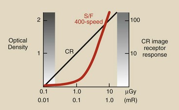
FIGURE 15-19 This region of the image receptor response curve suggests that significant patient radiation dose reduction may be possible with computed radiography (CR).
Lower radiographic technique that results in lower patient dose should be possible with CR if it were not for the image noise at low exposure. This will be discussed later for all DR modalities.
At this time, it should be emphasized that the conventional approach that “kVp controls contrast” and “mAs controls OD” does not hold for CR. Because CR image contrast is constant regardless of radiation exposure, images can be made at higher kVp and lower mAs, resulting in additional reduction in patient radiation dose.
Workload
The transition from screen-film radiography to CR brings several significant changes. Fewer repeat examinations should be needed because of the wide exposure latitude. Contrast resolution will be improved, and patient radiation dose may be reduced.
Radiographers will notice one less step in the workload described in Figure 15-1 (Figure 15-20). Because the CR reader is automatic and the IP reusable, there is no need to reload the cassette. But wait, it gets much better, as you will read in subsequent chapters.
Summary
The first applications of DR appeared in the early 1980s as CR. CR is based on the phenomenon of PSL.
X-rays interact with an SPS and form a latent image by exciting electrons to a higher energy metastable state. In the CR reader, the latent image is made visible by releasing the metastable electrons with a stimulating laser light beam.
On returning to the ground state, electrons emit shorter wavelength light in proportion to the intensity of the x-ray beam. The emitted light signal is digitized and reconstructed into a medical image.
The value of each CR pixel describes a linear characteristic curve over 4 decades of radiation exposure and a 10,000 gray scale. This wide latitude can result in reduced patient radiation dose and improved contrast resolution. A useful rule of thumb is that current “average” screen-film exposure factors represent the absolute maximum factors for the body part in CR.
1. Define or otherwise identify the following:
2. What workload steps are omitted when one is converting from screen-film radiography to computed radiography?
3. Identify three photostimulable phosphors.
4. How is the latent image formed in computed radiography?
5. What causes a photostimulable phosphor to appear turbid?
6. How do we reduce backscatter radiation in computed radiography, and why?
7. What is the approximate color of stimulating light and emitted light?
8. What is the purpose of an optical filter positioned before the photodetector?
9. What is the difference between fast scan and slow scan?
10. What is the difference between an analog signal and a digital signal?
11. What is the difference between sampling and quantization?
12. What is the purpose of a buffer?
13. Why is beam shaping required for the laser beam?
14. What are the three subsystems of a CR reader?
15. How is ghosting caused by residual latent image reduced?
16. What is the approximate difference in wavelength between prompt emission and stimulated emission?
17. How differently should one handle a computed radiography imaging plate compared with a screen-film cassette?
18. How is the latent image made visible in computed radiography?
19. What is the purpose of europium in a photostimulable phosphor?
20. Diagram the various layers of a computed radiography imaging plate.
The answers to the Challenge Questions can be found by logging on to our website at http://evolve.elsevier. com.