Digital Radiography
At the completion of this chapter, the student should be able to do the following:
1 Identify five digital radiographic modes in addition to computed radiography.
2 Define the difference between direct digital radiography and indirect digital radiography.
3 Describe the capture, coupling, and collection stages of each type of digital radiographic imaging system.
4 Discuss the use of silicon, selenium, cesium iodide, and gadolinium oxysulfide in digital radiography.
THE ACCELERATION to all-digital imaging continues because it provides several significant advantages over screen-film radiography.
Screen-film radiographic images require chemical processing, time that can delay completion of the examination. After an image has been obtained on film, little can be done to enhance the information content.
When the examination is complete, images are available in the form of hard copy film that must be catalogued, transported, and stored for future review. Furthermore, such images can be viewed only in a single place at one time.
These and other limitations are eliminated or reduced with the use of digital radiography (DR). This chapter describes various approaches to DR. Subsequent chapters present information on the digital image, the soft copy read of the digital image, and quality control measures for the digital image.
Because of its widespread application, computed radiography is discussed thoroughly in Chapter 15. This chapter discusses alternate approaches to DR.
Several approaches may be used to produce digital radiographs, and it is not yet clear whether one of these approaches ultimately will prevail. Furthermore, the vocabulary applied to digital radiography (DR) is not yet standard or universally accepted. The characterization and organization of DR as discussed in this book are illustrated in Figure 16-1.
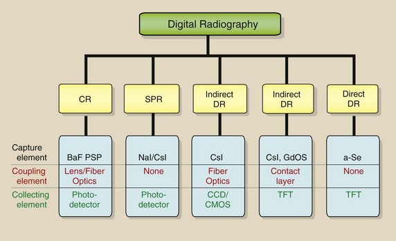
Ehsan Samei has reported a clever approach to describing and identifying the various DR imaging systems—capture element, coupling element, and collection element.
The capture element is that in which the x-ray is captured. In computed radiography (CR), the capture element is the photostimulable phosphor. In the other DR modes, the capture element may be sodium iodide (NaI), cesium iodide (CsI), gadolinium oxysulfide (GdOS), or amorphous selenium (a-Se).
The coupling element is that which transfers the x-ray–generated signal to the collection element. The coupling element may be a lens or fiberoptic assembly, a contact layer, or a-Se.
The collection element may be a photodiode, a charge-coupled device (CCD), or a thin-film transistor (TFT). The photodiode and the CCD are light-sensitive devices that collect light photons. The TFT is a charge-sensitive device that collects electrons.
Scanned Projection Radiography
Shortly after the introduction of third-generation computed tomography (CT), scanned projection radiography (SPR) was developed by CT vendors to facilitate patient positioning (Figure 16-2). It remains in use with virtually all current multislice helical CT imaging systems.
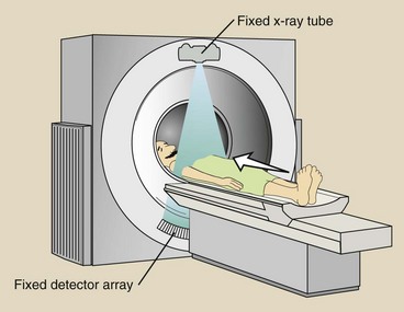
FIGURE 16-2 A scanned projection radiograph is obtained in computed tomography by maintaining the energized x-ray tube–detector array fixed while the patient is translated through the gantry.
Computed tomography vendors give this process various trademarked names, but SPR is similar for all. The patient is positioned on the CT couch and then is driven through the gantry while the x-ray tube is energized. The x-ray tube and the detector array do not rotate but are stationary, and the result is a digital radiograph (Figure 16-3).
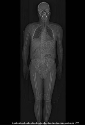
FIGURE 16-3 A scanned projection radiograph of the entire trunk of the body obtained in computed tomography. (Courtesy Colin Bray, Baylor College of Medicine.)
During the 1980s and the early 1990s, SPR was developed for dedicated chest DR (Figure 16-4). The principal advantage of SPR was collimation to a fan x-ray with associated scatter radiation rejection and improvement in image contrast.
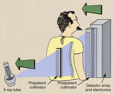
FIGURE 16-4 The components of a dedicated chest scanned projection radiography. (Courtesy Gary Barnes, University of Alabama, Birmingham.)
In SPR, the x-ray beam is collimated to a fan by prepatient collimators. Postpatient image-forming x-rays likewise are collimated to a fan that corresponds to the detector array—a scintillation phosphor, usually NaI or CsI—and is married to a linear array of CCDs through a fiberoptic light path.
This development was not very successful because chest anatomy has high subject contrast, so scatter radiation rejection is not all that important. Furthermore, the scanning motion required several seconds, resulting in motion blur.
At the present time, SPR is reemerging with some modification as a promising adjunct to digital radiographic tomosynthesis (DRT). The purpose of all forms of tomography is to improve image contrast, and that is the goal of DRT.
Charge-Coupled Device
The CCD was developed in the 1970s as a highly light-sensitive device for military use. It has since that time found major application in astronomy and digital photography.
The CCD, which is the light-sensing element for most digital cameras, has three principal advantageous imaging characteristics: sensitivity, dynamic range, and size. The CCD is a silicon-based semiconductor and is shown as an image receptor in Figure 16-5.
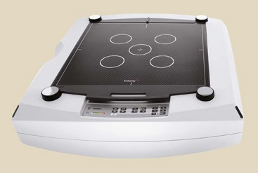
FIGURE 16-5 A tiled charge-coupled device (CCD) designed for digital radiography (DR) imaging. (Courtesy Bob Millar, Swissray.)
Sensitivity is the ability of the CCD to detect and respond to very low levels of visible light. This sensitivity is important for photographing the heavens through a telescope and for low patient radiation dose in digital imaging.
Dynamic range is the ability of the CCD to respond to a wide range of light intensity, from very dim to very bright. The dynamic range relative to that of a 400-speed screen-film radiographic image receptor is shown in Figure 16-6.
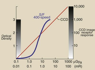
FIGURE 16-6 The radiation response of a charge-coupled device (CCD) compared with that of a 400-speed screen-film image receptor.
 The CCD has higher sensitivity for radiation and a much wider dynamic range than screen-film image receptors.
Note that the CCD radiation response is linear, but the screen-film image receptor has the characteristic Hurter and Driffield (H & D) curve response. Although the screen-film image receptor has 3 decades of radiation response—optical density (OD) from 0 to 3—only approximately 30 shades of gray are perceivable by the human eye. We attempt to produce radiographs low on the linear portion of the H & D curve to maximize image contrast at an acceptable patient radiation dose.
With the use of a CCD image contrast is unrelated to image receptor x-ray exposure. Furthermore, each of the 4 decades of radiation response—0 to 10,000—can be visualized by image postprocessing.
Also, it should be noted that at very low x-ray exposure, the response of a CCD system is greater than that of screen film. This should result in lower patient dose during DR.
A CCD is very small, making it highly adaptable to DR in its various forms. The CCD itself measures approximately 1 to 2 cm, but the pixel size is an exceptional 100 × 100 µm!
Cesium Iodide/ Charge-Coupled Device
One successful approach to DR is shown in Figure 16-7. This use of tiled CCDs receiving light from a scintillator allows the use of an area x-ray beam, so that, in contrast to SPR, exposure time is short. The image receptor shown in Figure 16-5 is of this type.
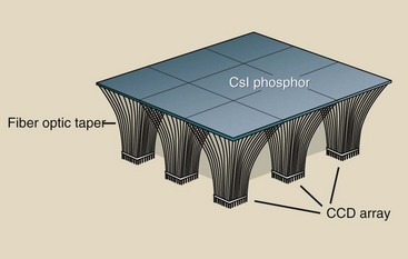
FIGURE 16-7 Charge-coupled devices (CCDs) can be tiled to receive the light from an area x-ray beam as it interacts with a scintillation phosphor such as cesium iodide (CsI).
The scintillation light from a CsI phosphor is efficiently transmitted through fiberoptic bundles to the CCD array. The result is high x-ray capture efficiency and good spatial resolution—up to 5 lp/mm. Figure 16-8 shows a versatile imaging system that is based on CsI and CCD technology.
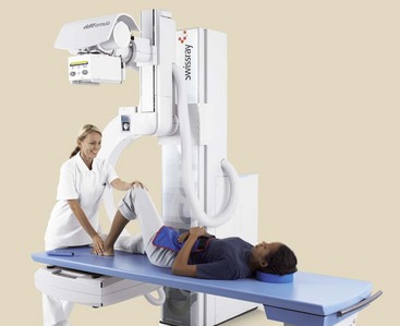
FIGURE 16-8 A versatile CsI flat panel digital radiographic imaging system. (Courtesy Bob Millar, Swissray.)
CsI/CCD is an indirect DR process by which x-rays are converted first to light and then to electric signal.
The assembly of multiple CCDs for the purpose of viewing an area x-ray beam presents the challenge to create a seamless image at the edge of each CCD. This is accomplished by interpolation of pixel values at each tile interface.
Cesium Iodide/Amorphous Silicon
An early application of DR involved the use of CsI to capture the x-ray, as in Figure 16-9, as well as transmission of the resulting scintillation light to a collection element. The collection element is silicon sandwiched as a TFT. Silicon is a semiconductor that usually is grown as a crystal. When identified as amorphous silicon (a-silicon), the silicon is not crystalline but is a fluid that can be painted onto a supporting surface.
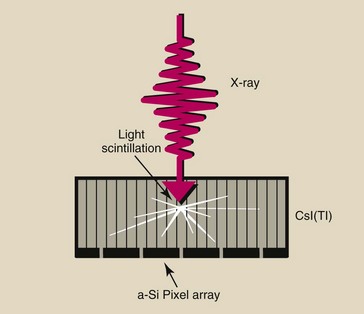
FIGURE 16-9 The cesium iodide (CsI) phosphor in digital radiography image receptors is available in the form of filaments to improve x-ray absorption and reduce light dispersion.
Cesium iodide has a high photoelectric capture because the atomic number of cesium is 55 and that of iodine is 53. Therefore, x-ray interaction with CsI is high, resulting in low patient radiation doses. The DR image receptor is fabricated into individual pixels, as shown in Figure 16-10. Each pixel has a light-sensitive face of a-Si with a capacitor and a TFT embedded.
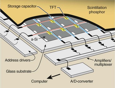
FIGURE 16-10 Digital radiographic images can be produced from the cesium iodide (CsI) phosphor light detected by the active matrix array (AMA) of silicon photodiodes.
CsI/a-Si is an indirect DR process by which x-rays are converted first to light and then to electric signal.
Figure 16-11 is a micrograph of an a-Si array that shows contacts for the switch control address drivers and the data lines. An exploded view of a single pixel shows that a large portion of the face of the pixel is covered by electronic components and wires that are not sensitive to the light emitted by the CsI phosphor.
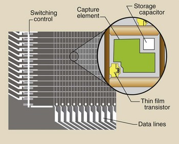
FIGURE 16-11 A photomicrograph of an active matrix array–thin-film transistor (AMA-TFT) digital radiography (DR) image receptor with a single pixel highlighted.
The geometry of each individual pixel is very important, as illustrated in Figure 16-12. Because a portion of the pixel face is occupied by conductors, capacitors, and the TFT, it is not totally sensitive to the incident image-forming x-ray beam.
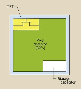
FIGURE 16-12 The fill factor is that portion of the pixel element that is occupied by the sensitive image receptor.
The percentage of the pixel face that is sensitive to x-rays is the fill factor. The fill factor is approximately 80%; therefore, 20% of the x-ray beam does not contribute to the image.
This represents one of the dilemmas for DR. As pixel size is reduced, spatial resolution improves but at the expense of the patient radiation dose. With smaller pixels, the fill factor is reduced, and x-ray intensity must be increased to maintain adequate signal strength. Much physics and materials science research in the nanometer range (nanotechnology) promises increased fill factor and improved spatial resolution at even lower patient radiation doses.
Cesium iodide has been used for years as the capture element of an image-intensifier tube. Similarly, GdOS has been widely used as the capture element of most rare earth radiographic intensifying screens.
What has been described for the CsI/a-Si image receptor can be repeated for the GdOS/a-Si image receptor. In screen-film radiographic imaging, GdOS thickness determines speed at the image receptor.
As GdOS screen-film speed was increased, spatial resolution was reduced because of light dispersion in the GdOS. Such is not the case with DR. Increasing thickness of GdOS in a DR image receptor increases the speed of the system with no compromise in spatial resolution.
Amorphous Selenium
The final DR modality is identified by some as direct DR because no scintillation phosphor is involved. The image-forming x-ray beam interacts directly with amorphous selenium (a-Se), producing a charged pair as shown in Figure 16-13. The a-Se is both the capture element and the coupling element.
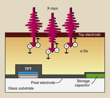
FIGURE 16-13 The use of amorphous selenium as an image receptor capture element eliminates the need for a scintillation phosphor.
The a-Se is approximately 200 µm thick and is sandwiched between charged electrodes. The entire image receptor would appear as that shown in Figure 16-10 for CsI/a-Si and described as an active matrix array (AMA) of TFTs.
X-rays incident on the a-Se create electron hole pairs through direct ionization of selenium. The created charge is collected by a storage capacitor and remains there until the signal is read by the switching action of the TFT.
Digital Mammography
Digital radiography received a large boost in the late 1990s with the application of DR to mammography, called digital mammography (DM). One might think that DR should have better spatial resolution than screen-film mammography because of the situation illustrated in Figure 16-14.
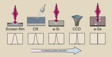
FIGURE 16-14 The line spread function is largest for screen-film mammography and least for amorphous selenium (a-Se) digital mammography.
Light from a radiographic intensifying screen spreads and exposes a rather large area of the film. The result is limited spatial resolution. The signal emitted during CR also spreads, limiting spatial resolution. The curves shown in Figure 16-14, called line spread functions, indicate the relative degree of spatial resolution.
According to the description provided for Figure 16-14, the use of a-Se for DR should result in the best spatial resolution. However, such is not the case because spatial resolution in DR is limited by pixel size, with the result that no DR system can match screen-film radiography for spatial resolution.
This topic is revisited in greater depth in Chapter 22. Figure 16-15 shows a digital mammographic system that is based on a-Se technology.
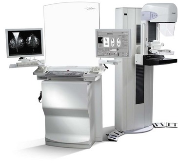
FIGURE 16-15 A digital mammographic imaging system based on amorphous selenium (a-Se) technology. (Courtesy Ande Stockland, Hologic.)
Digital mammography got a significant boost from the results of the Digital Mammography Imaging Study Trial (DMIST), which were released in early 2006. This investigation involved the imaging of nearly 50,000 women with screen-film mammography and DM interpreted from a properly designed viewing station (Figure 16-16).
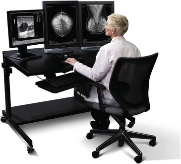
The stated intention of DMIST was to determine whether DM was as good as screen-film mammography. The suspicion was that it was not because the spatial resolution of DM (5 lp/mm) was much lower than that of screen-film mammography (15 lp/mm).
On the basis of radiologists’ interpretation, results showed that not only was DM equal to screen-film mammography for all patients, but it was also better for imaging dense, glandular breast tissue. This finding suggests that contrast resolution is more important than spatial resolution for mammography and possibly for all medical imaging. This is discussed further in Chapter 18.
Digital mammography tomosynthesis (DMT) is a recent advanced application of DM. With DMT, an area x-ray beam interacts with the digital mammographic image receptor, producing a digital mammogram. This digital mammogram is repeated several times at different angles, as shown in Figure 16-17.
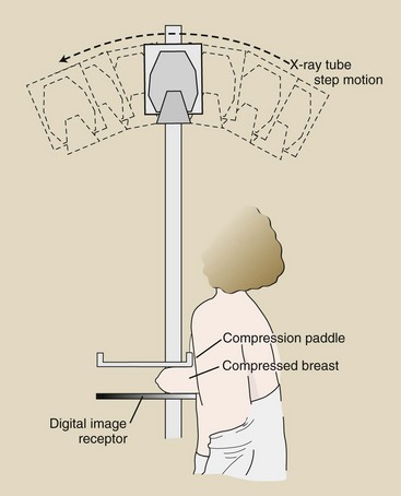
Each image is available in digital form and can be reconstructed as a three-dimensional matrix of values, each representing a voxel. This is not different from CT but occurs at substantially lower patient radiation dose. With these digital data available, a tomographic section can be reconstructed with enhanced image contrast at a patient radiation dose equal to that for screening mammography, less than 2 mGyt (200 mrad) (Figure 16-18).
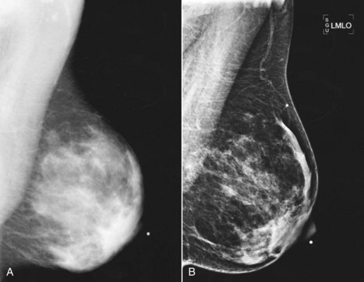
FIGURE 16-18 A, One view of a mammogram versus (B) the same anatomy viewed by digital mammography tomosynthesis. (Courtesy Loretta Hanset, Harris County Hospital District.)
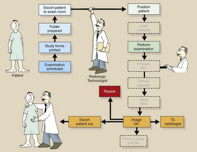
Figure 16-19 is a further rendition of the radiographic workflow for DR. Several additional steps are unnecessary.
Summary
Screen-film radiography has been the medical imaging process of choice for more than 100 years. Now, however, we are in the midst of a rapid transfer of technology to DR.
The earliest DR was a spin-off from CT and involved a collimated fan x-ray beam. SPR provides the advantage of scatter radiation reduction caused by x-ray beam collimation. The result is better contrast resolution but limited spatial resolution.
Spatial resolution is limited to pixel size in DR; this fact has held back the development of DR until recently. It is now clear that contrast resolution is more important in medical imaging, and in this area, DR prevails.
Currently, four methods are used to produce a digital projection radiograph. CR uses a photostimulable phosphor to generate a latent image. The visible image results when the PSL is scanned with a laser beam.
Cesium iodide (CsI) scintillation phosphor can be used as the capture element for image-forming x-rays. This signal is channeled to a CCD through fiberoptic channels.
Gadolinium oxysulfide or CsI is used to capture x-rays. The light from these scintillators is conducted to an AMA of TFTs, whose sensitive element is a-Si.
Finally, amorphous selenium is used as a capture element for x-rays in an alternate DR method.
A recent mammographic investigation (DMIST) has shown DR to be superior to screen-film mammography.
1. Define or otherwise identify the following:
2. Describe some applications for use of a CCD in addition to medical imaging.
3. What are the two principal phosphors used in DR?
4. What was the result of the DMIST investigation?
5. By what four methods can a digital radiograph be produced?
6. Why is interest in digital mammography tomosynthesis ongoing?
7. How does pixel size in CCD DR compare with that in other forms of DR?
8. Why is fill factor important?
9. How is the tiled CCD mosaic made to appear as a single image?
10. How does the image line spread function change for the four types of DR?
11. What properties make GdOS a good DR image receptor?
12. What is the principal advantage of SPR over tiled CCDs for use in DR?
13. What is the meaning of “sensitivity” in DR?
14. Describe the role of an AMA-TFT assembly.
15. Two conducting leads are present for each digital pixel. What are they, and what do they do?
16. How does DMT show promise for improved breast cancer detection?
17. What are the respective atomic numbers for the x-ray capture elements of the various DR systems?
18. What are the consequences of producing flat panel digital image receptors with smaller pixels?
19. What is meant by “limited spatial resolution?”
20. What are the capture, couple, and collection stages for a-Se–based DR?
The answers to the Challenge Questions can be found by logging on to our website at http://evolve.elsevier. com.