Viewing the Digital Radiographic Image
At the completion of this chapter, the student should be able to do the following:
1 Identify quantities and units used in photometry.
2 Explain the variation in luminous intensity of digital display devices.
3 Describe differences in hard copy and soft copy and in the interpretation of each.
4 Discuss the features of an active matrix liquid crystal display.
5 Describe the features of preprocessing and postprocessing.
6 Identify application of the picture archiving and communication system.
TO THIS point in medical imaging, understanding the physical concepts and associated quantities of energy and radiation has been necessary. The adoption of digital imaging and the “soft read” of images on a digital display device requires an understanding of an additional area of physics—photometry.
Photometry is the science of the response of the human eye to visible light. Refer to the discussion in Chapter 25 for an overview of human vision and a brief description of the anatomy of the eye.
Photometric Quantities
A description of human visual response is exceptionally complex and involves psychology, physiology, and physics, among other disciplines. The first attempt to quantify human vision was made in 1924 by the newly formed Commission Internationale de l’Éclairage (CIE) and included a definition of light intensity, the candle, the footcandle (fc), and candle power.
Response of the Eye
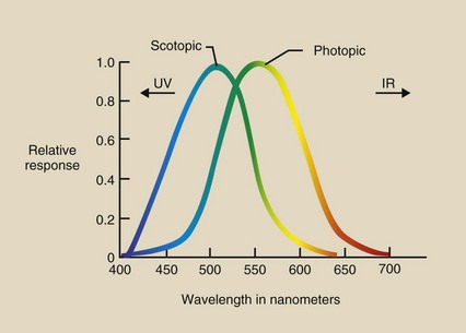
The CIE recognized the difference between photopic bright light vision with cones and scotopic dim light vision with rods. This resulted in the standard CIE photopic and scotopic response curves shown in Figure 18-1. Bright vision is best at 555 nm, and dim vision is best at 505 nm.
Photometric Units
Now radiologic technologists must have some familiarity with all units used to express photometric quantities. The basic unit of photometry is the lumen. It is scaled to the maximum photopic eye response at 555 nm.
Luminous flux, the fundamental quantity of photometry, is expressed in lumens (lm). Luminous flux is the total intensity of light from a source. Household lamps are rated by the power they consume in watts. An equally important value found on each lamp package is its luminous flux in lumens.
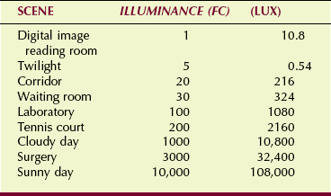
Illuminance describes the intensity of light incident on a surface. One lumen of luminous flux incident on a single square foot is a fc. This English unit, the fc, is still in wide use. The metric equivalent is 1 lumen per square meter, which is 1 lux (lx) (1 fc = 10.8 lux).
Luminance intensity is a property of the source of light, such as a viewbox or a digital display device. Luminance intensity is the luminous flux that is emitted into the entire viewing area; it is measured in lumens per steradian or candela.
Luminance is a quantity that is similar to luminance intensity. Luminance is another measure of the brightness of a source such as a digital display device expressed as units of candela per square meter or nit.
Table 18-1 summarizes these photometric quantities and their associated units.
TABLE 18-1
Photometric Quantities and Units
| Quantity | Units | Abbreviation |
| Luminous flux | Lumen | lm |
| Illuminance | Lumen/ft2 | fc |
| Lumen/m2 | lx | |
| Luminous intensity | Lumen/steradian | cd |
| Luminance | Candela/m2 | nit |
Table 18-2 shows the range of illuminance for several familiar situations. Most indoor work and play areas are illuminated to 100 to 200 fc.
Cosine Law
Two fundamental laws are associated with photometry. Luminous intensity decreases in proportion to the inverse square of the distance from the source. This is the famous inverse square law (see Chapter 3).
The cosine law is important when one is describing the luminous intensity of a digital display device. When a monitor is viewed straight on, the luminous intensity is maximum. When a monitor is viewed from an angle, the contrast and the luminous intensity, as seen in Figure 18-2, are reduced.
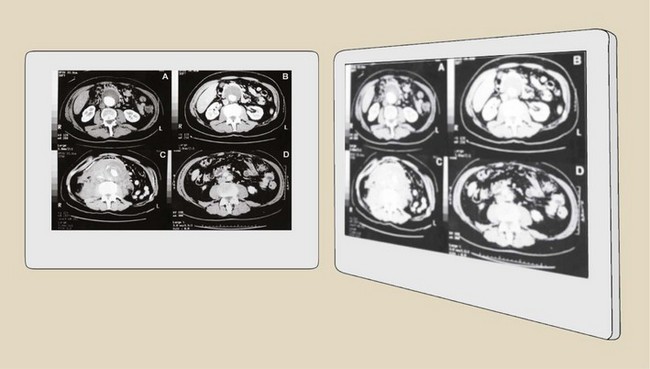
FIGURE 18-2 When a digital display device is viewed from the side, illumination and image contrast are reduced.
This reduced projected surface area follows a mathematical function called a cosine. Luminous intensity falls off rapidly as one views a digital display device at larger angles from perpendicular.
Hard Copy–soft Copy
Until the mid 1990s, essentially all medical images were “hard copy,” that is, the images were presented to the radiologist on film. The image was interpreted from the film, which was positioned on a lighted viewbox.
Computed tomography (CT) (1974) and magnetic resonance imaging (MRI) (1980) represent the first widespread digital medical images. However, until recently, even these digital images were interpreted from film placed on a lighted viewbox.
Now, essentially all digital images are interpreted from presentation on a digital display device. The knowledge required of a radiologic technologist regarding the viewing of a film image on a viewbox is rather simple. The knowledge required for soft copy viewing on a digital display device is not only different but difficult.
Soft copy viewing is performed on a digital cathode ray tube (CRT) or an active matrix liquid crystal display (AMLCD). The essentials of CRT imaging are discussed in Chapter 25.
This chapter concentrates on the AMLCD as the principal soft copy digital display device now being universally adopted.
Active Matrix Liquid Crystal Display
We all know that matter takes the form of gas, liquid, or solid. A liquid crystal is a material state between that of a liquid and a solid.
A liquid crystal has the property of a highly ordered molecular structure—a crystal—and the property of viscosity—a fluid. Liquid crystal materials are linear organic molecules (Figure 18-3) that are electrically charged, forming a natural molecular dipole. Consequently, the liquid crystals can be aligned through the action of an external electric field.
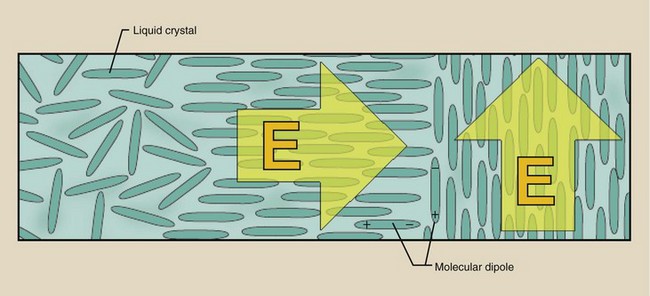
FIGURE 18-3 Liquid crystals are randomly oriented in the natural state and are structured under the influence of an external electric field.
Display Characteristics
Active matrix liquid crystal displays are fashioned pixel by pixel. The AMLCD has a very intense white backlight that illuminates each pixel. Each pixel contains light-polarizing filters and films to control the intensity and color of light transmitted through the pixel.
The differences between color and monochrome AMLCDs involve the design of the filters and films. Color AMLCDs have red-green-blue filters within each pixel fashioned into subpixels, each with one of these three filters.
Medical flat panel digital display devices are monochrome AMLCDs. Figure 18-4 illustrates the design and operation of a single pixel. A backlight illuminates the pixel and is blocked or transmitted by the orientation of the liquid crystals.
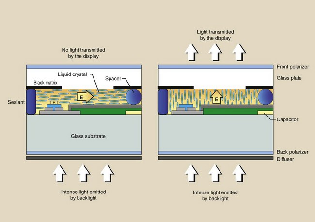
FIGURE 18-4 Cross-sectional rendering of one pixel of an active matrix liquid crystal display (AMLCD).
The pixel consists of two glass plate substrates that are separated by embedded spherical glass beads of a few microns in diameter that act as spacers. Additionally, bus lines—conductors—control each pixel with a thin-film transistor (TFT).
Medical flat panel digital display devices are identified by the number of pixels in the AMLCD. A 1-megapixel display will have a 1000- × 1000-pixel arrangement. A high-resolution monitor will have a 5-megapixel display, or a 2000- × 2500-pixel arrangement. Table 18-3 reports the matrix array for popular medical flat panel digital display devices.
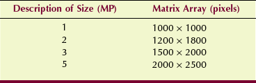
Image Luminance
The AMLCD is a very inefficient device. Only approximately 10% of the backlight is transmitted through a monochrome monitor and half of that through a color monitor. This inefficiency is partly attributable to light absorption in the filters and polarizers. Because a substantial portion of each pixel is blocked by the TFT and the bus lines, efficiency is reduced still further.
The portion of the pixel face that is available to transmit light is the “aperture ratio.” Aperture ratio is to a digital display device as “fill factor” is to a digital radiographic detector. Aperture ratios of 50% to 80% are characteristic of medical AMLCDs.
The term active in AMLCD refers to the ability to control individually each pixel of the digital display device. This differs from the nature of reading a digital image receptor line by line, which is called a “passive” read. The TFT is required for the active read.
Some of the principal differences between digital CRT displays and AMLCDs are shown in Table 18-4. AMLCDs are rapidly replacing CRTs in digital radiography (DR) because most of these characteristics favor the AMLCD.
TABLE 18-4
Principal Differences Between Cathode Ray Tube and Active Matrix Liquid Crystal Display Digital Display Devices
| CRT | AMLCD |
| Light emitting | Light modulating |
| Curved face | Flat face |
| Scanning electron beam | Active matrix address |
| Veiling glare distortion | Pixel cross-talk distortion |
| Spot pixel | Square pixel |
| Phosphor nonuniformity | LC nonuniformity |
AMLCD, active matrix liquid crystal display; CRT, cathode ray tube; LC, liquid crystal.
Active matrix liquid crystal displays have better grayscale definition than CRTs. AMLCDs are not limited by veiling glare or reflections in the glass faceplate; thus, better contrast resolution is attained. The intrinsic noise of an AMLCD is less than that of a CRT; this also results in better contrast resolution.
Ambient Light
Active matrix liquid crystal displays are designed to better reduce the influence of ambient light on image contrast. The principal disadvantage of an AMLCD is the angular dependence of viewing. Figure 18-5 shows that the image contrast falls sharply as the viewing angle increases.
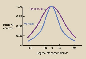
FIGURE 18-5 Loss of image contrast as a function of off-perpendicular viewing of an active matrix liquid crystal display (AMLCD).
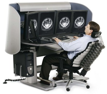
This characteristic of flat panel digital display devices has led to considerable ergonomic design of digital workstations. Ergonomics is the act of matching a worker to the work environment for maximum efficiency.
Figure 18-6 shows an example of an ergonomically designed digital image workstation. Levels of ambient light at the workstation must be reduced to near darkness for best viewing.
Preprocessing THE Digital Radiographic Image
A principal advantage of digital radiographic imaging over screen-film radiographic imaging is the ability to manipulate the image before display—preprocessing—and after display—postprocessing. Preimage processing and postimage processing alter image appearance, usually for the purpose of improving image contrast.
Preprocessing actions are outlined in Table 18-5. Preprocessing is designed to produce artifact-free digital images. In this regard, preprocessing provides electronic calibration to reduce pixel-to-pixel, row-to-row, and column-to-column response differences. The processes of pixel interpolation, lag correction, and noise correction are automatically applied with most systems.
TABLE 18-5
| Problem | Solution |
| Defective pixel | Interpolate adjacent pixel signals |
| Image lag | Offset correction |
| Line noise | Correct from dark reference zone |
Offset images and gain images are automatic calibration images designed to make the response of the image receptor uniform. Gain images are generated every few months, and offset images are generated many times each day.
These preprocessing calibration techniques are identified as flatfielding and are shown in Figure 18-7. Averaging techniques also are used to reduce noise and improve contrast.

FIGURE 18-7 A, Exposure to a raw x-ray beam shows the heel effect on the image. B, Flatfielding corrects this defect and makes the image receptor response uniform. (Courtesy Anthony Siebert, University of California, Davis.)
Digital image receptors and display devices have millions of pixels; therefore, it is reasonable to expect some individual pixels to be defective and to respond differently or not at all. Such defects are corrected by signal interpolation. The response of pixels surrounding the defective pixel is averaged, and that value is assigned to the defective pixel.
Each type of digital image receptor generates an electronic latent image that may not be made visible completely. What remains is image lag, and this can be troublesome when one is switching from high-dose to low-dose techniques, such as switching from digital subtraction angiography (DSA) to fluoroscopy. The solution is application of an offset voltage before the next image is acquired.
Some voltage variations may be seen along the buses that drive each pixel. This defect, called line noise, can cause linear artifacts to appear on the final image. The solution is to apply a voltage correction from a row or a column of pixels in a dark, unirradiated area of the image receptor.
Postprocessing The Radiographic Digital Image
Postprocessing is where digital imaging shines. In contrast to preprocessing, which is largely automatic, postprocessing requires intervention by the radiologic technologist and the radiologist. Postprocessing refers to anything that can be done to a digital radiographic image after it is acquired by the imaging system.
Postprocessing of the digital radiographic image is performed to optimize the appearance of the image for the purpose of better detecting pathology. Table 18-6 lists the more useful postprocessing functions.
TABLE 18-6
| Process | Results |
| Annotation | Label the image |
| Window and level | Expand the digital grayscale to visible |
| Magnification | Improve visualization and spatial resolution |
| Image flip | Reorient image presentation |
| Image inversion | Make white-black and black-white |
| Subtraction (DSA) | Improve image contrast |
| Pixel shift | Reregister an image to correct for patient motion |
| Region of interest | Determine average pixel value for use in quantitative imaging |
Annotation is the process of adding text to an image. In addition to patient identification, annotation is often helpful in informing the clinician about anatomy and diagnosis.
Digital images have dynamic ranges up to 16-bit, 65,536-gray levels. However, the human visual system can visualize only approximately 30 shades of gray. By window and level adjustment, the radiologic technologist can make all 65,536 shades of gray visible. This amplification of image contrast may be the most important feature of digital radiographic imaging.
The larger matrix size digital display devices have better spatial resolution because they have smaller pixels. This allows, among other properties, magnification of a region of an image to render the smallest detail visible. Magnification in digital imaging is similar to using a magnifying glass with a film image.
At times, multiple digital images must be flipped horizontally or vertically. This process, called image flip, is used to bring images into standard viewing order.
Most digital radiographic images are viewed through the contrast rendition of screen-film images: Bone is white, and soft tissue is black. However, sometimes pathology can be made more visible with image inversion, which results in a black appearance of bone and a white appearance of soft tissue (Figure 18-8).
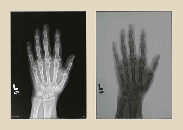
FIGURE 18-8 Digital image inversion is sometimes helpful in making disease more visible, as in this case of a digital hand image. (Courtesy Colin Bray, Baylor College of Medicine.)
Image subtraction, as used in DSA, is discussed in Chapter 26. Subtraction of digital radiographic images obtained months apart—temporal subtraction—is used to amplify changes in anatomy or disease. The purpose of image subtraction is to enhance contrast.
Misregistration of a subtraction image occurs when the patient moves during serial image acquisition. This can be corrected by re-registering the image through a technique called pixel shift.
Greater use is being made of quantitative imaging, that is, use of the numeric value of pixels to help in diagnosis. This requires identifying a region of interest (ROI) and computing the mean pixel value for that ROI. This is an area of digital imaging that has been identified as quantitative radiology; it is finding application in bone mineral assay, calcified lung nodule detection, and renal stone identification.
Edge enhancement is effective for fractures and small, high-contrast tissues. Highlighting can be effective in identifying diffuse, nonfocal disease. Pan, scroll, and zoom allows for careful visualization of precise regions of an image.
Picture Archiving and Communication System
Radiology is adopting digital imaging very rapidly. Estimates of the present level of digitally acquired images range up to 90%.
These digital images come from every area of medical imaging, including nuclear medicine, diagnostic ultrasonography, radiography, fluoroscopy, CT, and MRI. Screen-film radiographs can be digitized with the use of a device such as that shown in Figure 18-9. Such film digitizers are based on laser beam technology.
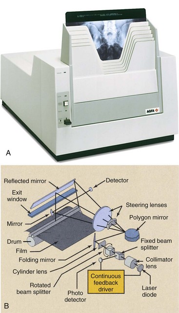
Figure 18-9 A, A thin film digitizer uses a laser beam to convert an analog radiograph into a digital image. B, The printing to film is similar to that of a laser printer. (A courtesy Agfa; B courtesy Imation.)
A picture archiving and communication system (PACS), when fully implemented, allows not only the acquisition but also the interpretation and storage of each medical image in digital form without resorting to film (hard copy). The projected efficiencies of time and cost are enormous.
The four principal components of a PACS are the image acquisition system, the display system, the network, and the storage system. Chapter 16 presents digital image acquisition, and the earlier sections of this chapter have discussed the digital display system.
Network
To be truly effective, each of these image-processing modes must be quick and easy to use. This requires that each workstation must be microprocessor controlled and must interact with each imaging system and the central computer. To provide for such interaction, a network is required.
Computer scientists use the term network to describe the manner in which many computers can be connected to interact with one another. In a business office, for instance, each secretary might have a microprocessor-based workstation, which is interfaced with a central office computer, so that information can be transferred from one workstation to another or to and from a main computer or server.
In some countries, national networks are used for medical data. All patients have a unique identifier, a number that is exclusively theirs for life.
Any hospital at any time can enter the unique identifier and access the medical records for that patient. At the moment, this is primarily limited to text, but as PACS networks expand, the system now includes images.
In radiology, in addition to secretarial workstations, the network may consist of various types of devices that allow storage, retrieval, and viewing of images, PACS workstations, remote PACS workstations, a departmental mainframe, and a hospital mainframe (Figure 18-10). Each of these devices is called a client of the network.
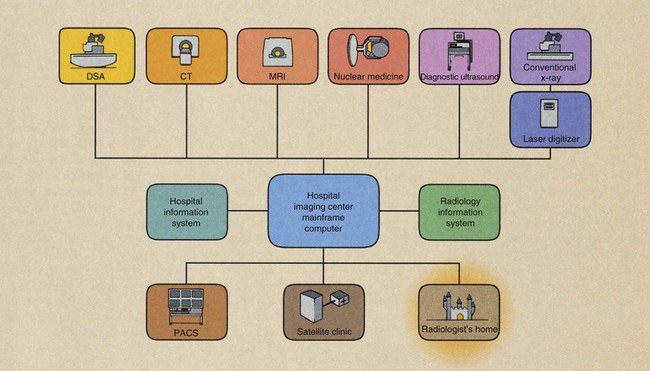
FIGURE 18-10 The picture archiving and communication system (PACS) network allows interaction among the various modes of data acquisition, image processing, and image archiving.
 Clients are interconnected, usually by cable in a building, by telephone or cable television lines among buildings, and by microwave or satellite transmission to remote facilities.
Teleradiology is the process of remote transmission and viewing of images. To ensure adaptability among different imaging systems, the American College of Radiology, in cooperation with the National Electrical Manufacturers Association, has produced a standard imaging and interface format called Digital Imaging and Communications in Medicine (DICOM).
The network begins at the digital imaging system, where data are acquired. Images reconstructed from data are processed at the console of the imaging system or are transmitted to a PACS workstation for processing.
At any time, such images can be transferred to other clients within or outside the hospital. Instead of running films up to surgery for viewing on a viewbox, one simply transfers the image electronically to the PACS workstation in surgery.
When a radiologist is not immediately available for image interpretation, the image can be transferred to a PACS workstation in the radiologist’s home. Essentially, everywhere that film used to be required, electronic images can be substituted. Time is essential when one is considering image manipulation; therefore, fast computers and networks with broad bandwidth are required for this task.
These requirements are relaxed for the information management and database portion of PACS, which is the Radiology Information System (RIS). Such lower priority RIS functions include message and mail utilities, calendar reporting, storage of text data, and financial accounting and planning.
From the RIS workstation, any number of coded diagnostic reports can be initiated and transferred to a secretarial workstation for report generation. The secretarial workstation in turn can communicate with the main hospital computer for patient identification, billing, accounting, and interaction with other departments.
Such interconnection allows for the “pre-fetching” of images from the archive. The moment a patient reports to any reception desk anywhere in the facility, the process of recovering archived records commences automatically. By the time the patient reaches the examination room, all previous images and reports are available.
Similarly, a secretarial workstation at the departmental reception desk can interact with a departmental computer for scheduling of patients, technologists, and radiologists and for analysis of departmental statistics. Finally, at the completion of an examination, PACS allows for more efficient image archiving.
Many applications now exist for electronic notepads and telephones that allow these mobile devices to serve as viewing stations. Concerns for patient confidentiality continue, but clearly remote mobile digital radiographic viewing is here.
Storage System
One motivation for PACS is archiving. How often are films checked out from the file room and never returned? How many films disappear from jackets? How many jackets disappear? How often are films copied for clinicians?
Just the cost of the hospital space to accommodate a film file room may be sufficient to justify PACS.
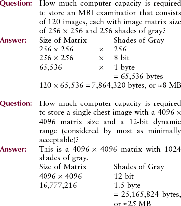
Image storage requirements are determined by the number of images and the image data file size. Image file size is the product of the matrix size and the grayscale bit depth. The following examples should help with this understanding.
With PACS, a film file room is replaced by a magnetic or optical memory device. The future of PACS, however, depends on the continuing development of the optical disc.
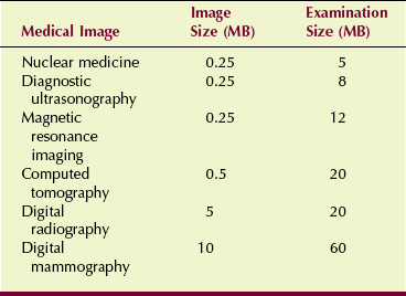
Optical discs can accommodate tens of gigabytes (GB) of data and images and, when stored in a “jukebox” (see Figure 14-13), can accommodate terabytes (TB). However, because of the dynamic range of DR and digital mammography, file storage is stretched. Table 18-7 shows the file size for various medical images.
An entire hospital file room can be accommodated by a storage device the size of a desk. Electronically, images can be recalled from this archival system to any workstation in seconds. Backup image storage is accommodated offsite at a digital data storage vendor in the case that the main file is corrupted.
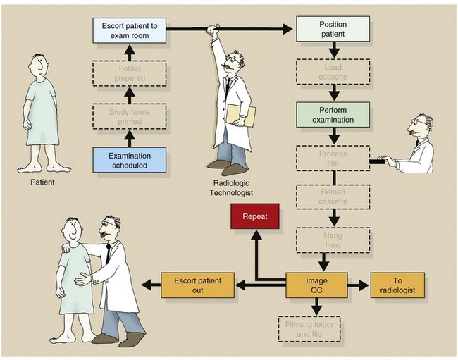
Furthermore, by using PACS with digital imaging, the workflow chart is greatly reduced, as is shown in Figure 18-11. This leads to much improved imaging efficiency.
Summary
Viewing of digital images requires that radiologic technologists have an introductory knowledge of photometry. Knowledge of photometric units and concepts is essential to successful digital radiographic imaging. Photopic vision and scotopic vision are used for viewing of digital images.
The AMLCD is the principal system for viewing soft copy digital images. The characteristics of an AMLCD affect image luminance. Ambient light is also of great consideration with the use of an AMLCD.
Preprocessing and postprocessing of the digital image are the properties that propel digital imaging to be superior to analog medical imaging.
The PACS is the design for integrating medical images into the health care environment. Among other characteristics, the film file room is replaced by electronic memory devices the size of a box. Teleradiology is the remote transmission of digital images even to handheld mobile devices.
1. Define or otherwise identify the following:
2. What is image registration, and how is it used?
3. Describe the effect of off-axis viewing of a digital display system.
4. What equipment is required to implement teleradiology?
5. What portion of medical imaging is now digital?
6. What photometric quantity best describes image brightness?
7. Describe the properties of a liquid crystal.
8. How much digital capacity is required to store a 2000 × 2500 digital mammogram with a 16-bit grayscale?
9. How is interpolation used to preprocess a digital image?
10. What is the difference between bright vision and dim vision?
11. What is the approximate illumination of an office, major league night baseball, and a sunny snow scene?
12. How is DICOM used with medical images?
13. Briefly, how does an AMLCD work?
14. What is the difference between monochrome and polychrome?
15. What are some advantages of digital display devices over a digital cathode ray tube?
17. If the transmission speed of a teleradiology system is 1 MB/s, how long will it take to transmit two 3-MB chest images with a 12-bit grayscale?
18. What is the aperture ratio of a medical AMLCD?
19. What ergonomic properties are incorporated into a digital image workstation?
The answers to the Challenge Questions can be found by logging on to our website at http://evolve.elsevier. com.