Mammography Quality Control
At the completion of this chapter, the student should be able to do the following:
1 Define quality control and its relationship to quality assurance.
2 List the members of the quality control team in radiology.
3 Describe the role of the radiologist and the medical physicist in quality control.
4 List the film processor quality control steps.
5 Itemize the mammographer’s quality control duties for both screen-film and digital imaging.
MAMMOGRAPHY HAS been a screening and diagnostic tool for many years, but challenges in producing high-quality mammographic images while keeping patient radiation doses low are ongoing. A team that includes a radiologist, medical physicist, and mammographer works together using a quality control (QC) program to produce excellence in mammographic imaging. Each member of the team is assigned specific tasks that relate to QC. This chapter identifies these responsibilities.
Quality Control Team
The American College of Radiology (ACR) and the Mammography Quality Standards Act (MQSA) have endorsed a QC program of specific duties required of radiologists, medical physicists, and mammographers (Figure 24-1). Each of these individuals is important in ensuring the best available patient care with an acceptable patient radiation dose. This chapter discusses the responsibilities of each of these three positions but emphasizes the mammographer’s duties.

Radiologist
The ultimate responsibility for mammography QC lies with the radiologist. These responsibilities often fall under the more broad area of quality assurance (QA). QA is an administrative program that is designed to fuse the different aspects of QC and to ensure that all activities are carried out at the highest level. The radiologist is responsible for selecting qualified medical physicists and mammographers and for overseeing the activities of these team members regularly.
Another responsibility of the radiologist involves supervising patient communication and tracking. Quality patient care is the ultimate goal of any mammography facility, and the final responsibility for this goal lies with the radiologist. The level of any QA and QC program directly reflects the radiologist’s attitude and appreciation for the need for such a program. The MQSA mandates daily “clinical image evaluation” by the radiologist. Continuous quality improvement (CQI) is an extension of any QA and QC program, including administrative protocols for the continuous improvement of mammographic image quality.
Medical Physicist
The role of the medical physicist as a member of the mammography QC team is multidimensional. One such aspect is QC evaluation of the physical equipment used to produce an image of the breast. This evaluation should be performed annually or whenever a major component has been replaced. The evaluation consists of a number of measurements and tests that are summarized in Box 24-1.
The medical physicist should understand how the different technical aspects of the imaging chain affect the resulting image and therefore should be able to identify existing or potential image-quality problems. Occasionally, the medical physicist may pass information directly to the service engineer or may serve as an intermediary between the facility and the service engineer. The aim of this portion of the QC program is to ensure that imaging systems function properly to provide the highest quality images with the lowest patient radiation dose.
 The medical physicist’s principal responsibility is to conduct an annual performance evaluation of the imaging system.
Another role of the medical physicist is to advise the mammographer. The medical physicist should understand all tests expected of the mammographer well enough to predict likely problems or complications.
An additional responsibility is to evaluate the QC program on site at least annually. The medical physicist should review all procedures to ensure compliance with current recommendations and standards. The medical physicist should thoroughly review charts and records to check for compliance and to ensure that they are prepared properly and contain all of the necessary information.
The medical physicist is an integral part of the QC team whose full cooperation and attention are expected. This very achievable goal involves maintenance of a first-class QC program by a competent mammographer. The mammographer must call the medical physicist whenever images or the imaging system changes substantially.
Mammographer
The mammographer is a radiologic technologist and is extremely important to a mammography QC program. The mammographer, the most hands-on member of the QC team, is responsible for day-to-day QC and for producing and monitoring all control charts and logs for any trends that might indicate problems. In imaging facilities that use several mammographers, one should be assigned the responsibility of QC mammographer.
The 12 specific QC tasks for which the mammographer is responsible may be broken into categories that reflect frequency of performance. Table 24-1 outlines these tasks and estimates the time that each task requires for screen-film mammography.
TABLE 24-1
Elements of a Screen-film Mammographic Quality Control Program
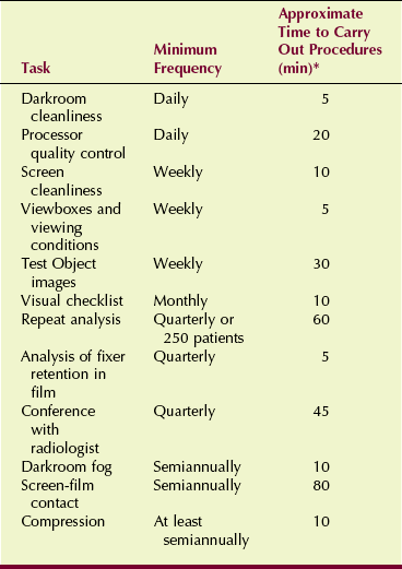
*Total annual time required for quality control: 160 hours.
Screen-Film Quality Control
The mammographer’s routine tasks are well defined, with recommended performance standards available for each of them. To maintain a thorough and accurate QC program, the mammographer must fully understand these tasks and the reasons for recommended performance standards.
Daily Tasks
The first task each day is to wipe the darkroom clean. Maintaining the cleanest possible conditions in the darkroom minimizes artifacts on mammograms (Figure 24-2). First, the floor should be damp mopped. Next, all unnecessary items should be removed from countertops and work surfaces. A clean, damp towel should be used to wipe off the film processor feed tray and all countertops and work surfaces.
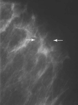
FIGURE 24-2 These specks were produced by flakes trapped between the film and the screen. (Courtesy Susan Sprinkle-Vincent, Advanced Health Education Center.)
If a passbox is present, it should be cleaned daily as well. Hands should be kept clean to minimize fingerprints and handling artifacts. Overhead air vents and safelights should be wiped or vacuumed weekly before the other cleaning procedures are performed. Even the ceiling tiles should be cleaned to prevent flaking.
Smoking, eating, and drinking in the darkroom is prohibited. Food or drink should not be taken into the darkroom at any time. Nothing should be left on the countertop except items used for loading and unloading cassettes because other objects would only collect dust. No shelves should be included above the countertops in the darkroom because these also serve as sites for dust collection; such dust eventually falls onto work surfaces.
Processor Quality Control
Before any films are processed, it should be verified that the processor chemical system is in accord with preset specifications. The first step in a processor QC program is to establish operating control levels. To begin, a new dedicated box of film should be set aside to carry out the future daily processor QC. The processor tanks and racks should be cleaned and the processor supplied with the proper developer replenisher, fixer, and developer starter fluids as specified by the manufacturer.
The developer temperature and developer and fixer replenishment rates should also be set to the levels specified by the manufacturer. A mercury thermometer should never be used. If the thermometer breaks, mercury contamination could render the processor permanently useless.
After the processor has been allowed to warm up and the developer is at the correct temperature and stable, testing may continue. In the darkroom, a sheet of control film should be exposed with a sensitometer (Figure 24-3). The sensitometric strip should always be processed in exactly the same manner. The least exposed end is fed into the processor first. The same side of the feed tray is used with the emulsion side down. The time between exposure and processing should be similar each day.
Next, a densitometer is used to measure and record the optical density (OD) of each of the steps on the sensitometric strip. This process should be repeated each day for 5 consecutive days. The average OD is then determined for each step from the five different strips.
After the averages have been determined, the step that has an average OD closest to 1.2 but not less than 1.2 should be identified and marked as the mid-density (MD) step for future comparison. This is sometimes called the speed index.
Next, the step with an average OD closest to 2.2 and the step with an average OD closest to but not less than 0.5 should be found and marked for future comparison. The difference between these two steps is recorded as the density difference (DD), which is sometimes called the contrast index.
Finally, the average OD from an unexposed area of the strips is recorded as the base plus fog (B+F). The three values that have now been determined should be recorded on the center lines of the appropriate control chart. An example of a control chart is shown in Figure 24-4.
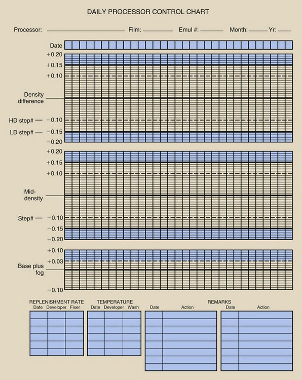
FIGURE 24-4 An example of the type of processor quality control record that should be maintained for each processor.
After the control values have been established, the daily processor QC begins. At the beginning of each day, before any films are processed, a sensitometric strip should be exposed and processed according to the guidelines previously discussed. The MD, DD, and B+F are each determined from the appropriate predetermined steps and are plotted on the control charts.
The MD is determined to evaluate the constancy of image receptor speed. The DD is determined to evaluate the constancy of image contrast. These values are allowed to vary within 0.15 of the control values. If either value is out of this control limit, the point should be circled on the graph, the cause of the problem corrected, and the test repeated.
If the value of the MD or the DD cannot be brought within the 0.15 variance of control, no clinical images should be processed.
If either value falls by ±0.1 outside the range of the control value, the test should be repeated. If the value continues to remain outside this range, the processor may be used for clinical processing but should be monitored closely while the problem is identified.
The B+F evaluates the level of fog in the processing chain. This value is allowed to vary within 0.03 of the control value. Any time the value exceeds this limit, steps should be taken as described for the MD and DD values.
Weekly Tasks
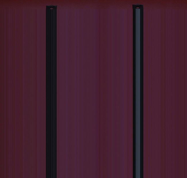
Screens are cleaned to ensure that mammographic cassettes and intensifying screens are free of dust and dirt particles, which can resemble microcalcifications and may result in misdiagnoses. Radiographic intensifying screens should be cleaned with the use of the material and methods suggested by the screen manufacturer. If a liquid cleaner is used, screens should be allowed to air dry while standing vertically, as shown in Figure 24-5, before the cassettes are closed or used. If compressed air is used, the air supply should be checked to ensure that no moisture, oil, or other contaminants are present.
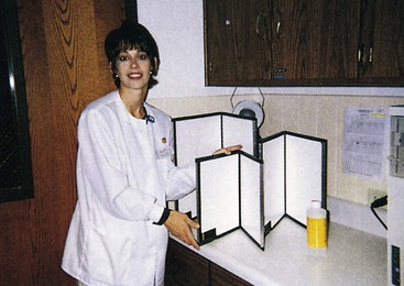
FIGURE 24-5 The proper way to dry screens after cleaning is to position them vertically. (Courtesy Linda Joppe, Rasmussen College.)
Each screen cassette combination should be clearly labeled. Identifying information should be placed on the exterior of the cassette, as well as on a lateral border of the screen, so it will be legible on the processed film. This enables the mammographer to identify specific screens that have been found to contain artifacts.
Viewboxes and Viewing Conditions
Viewboxes and viewing conditions must be maintained at an optimal level. Viewbox surfaces should be cleaned with window cleaner and soft paper towels, ensuring that all marks have been removed.
The viewboxes should be visually inspected for uniformity of luminance and to ensure that all masking devices are functioning properly. Room illumination levels should be checked visually as well to ensure that the room is free of bright light and that the viewbox surface is free of reflections. The viewing conditions for mammographers when checking films should be the same as those for radiologists.
Any marks that are not removed easily require an appropriate cleaner that will not damage the viewbox. If the viewbox luminance appears to be nonuniform, all of the interior lamps should be replaced. Mammography viewboxes have considerably higher luminance levels than conventional viewboxes. A luminance of at least 3000 NIT (candela per square meter) is required.
All mammograms and mammography test images should be completely masked for viewing, so that no extraneous light from the viewbox enters the viewer’s eyes. Masking can be provided simply by cutting black paper to the proper size (Figure 24-6). Commercially adjustable masks are available.
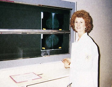
FIGURE 24-6 Screen-film mammograms must be masked for proper viewing. (Courtesy Lois Depouw, Rasmussen College.)
Ambient light in the area of the viewbox should be diffused and reduced to approximately the same level as that reaching the eye through the mammogram. Sources of glare must be removed and surface reflections eliminated.
Test Object Images
Test object images are taken to ensure optimal OD, contrast, uniformity, and image quality of the x-ray imaging system and film processor. A standard film and a cassette designated as the control cassette should be used to take an image of an MQSA accreditation test object.
The test object should be placed on the image receptor assembly so that its edge is aligned with the chest wall edge of the image receptor, as shown in Figure 24-7. The compression device should be brought into contact with the test object, and the automatic exposure control sensor should be positioned in a location that will be used for all future test object images.
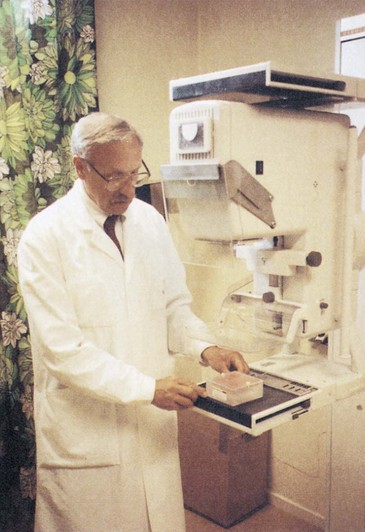
FIGURE 24-7 Analysis of an image of the American College of Radiology mammography test object by a medical physicist scores the detection limits of the system for fibrils, microcalcifications, and nodules. (Courtesy Art Haus, Ohio State University.)
The technique selected for imaging the test object should be the same that is used clinically for a 50% adipose/50% glandular, 4.5-cm compressed breast. When the exposure is made, the time or milliampere seconds (mAs) value is recorded. The film should then be processed similarly to a clinical mammogram.
A densitometer is used to determine the OD for the density disc and for the background immediately adjacent to the density disc. The time or mAs value recorded earlier, the background OD, and the DD should be plotted on a test object image control chart such as the one shown in Figure 24-8.
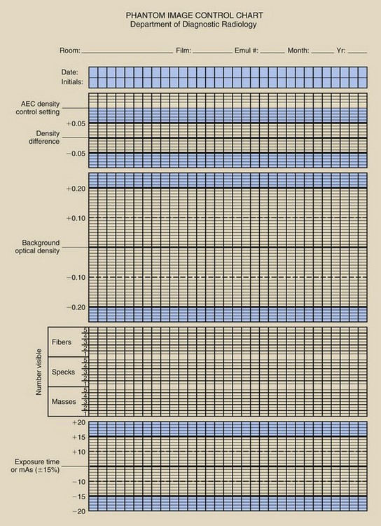
The exposure time or mAs value should stay within a range of ±15%. The background OD of the film should be approximately 1.4, with an allowed range of ±0.2. A good target value is approximately 1.6. The DD should be approximately 0.4, with an allowed range of ±0.05. However, this is defined for 28 kilovolt peak (kVp), so slightly different ODs should be expected at other kVp values.
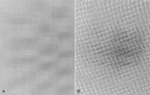
The next step is to score the test object image. This involves determining the number of fibers, speck groups, and masses visible in the test object image. The ACR accreditation test object and its image are shown in Figure 24-9. These results also should be plotted on the test object image control chart.
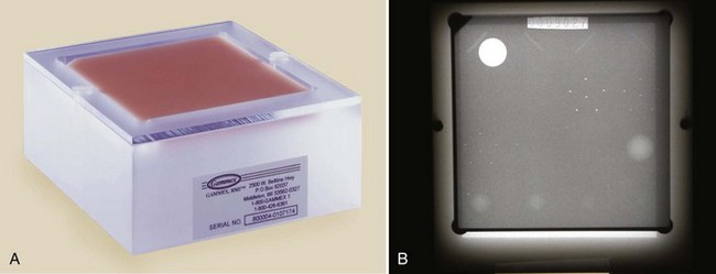
FIGURE 24-9 A, The American College of Radiology accreditation test object. B, Its image. (Courtesy Gammex RMI.)
Scoring of objects requires that they must always be counted from the largest object to the smallest, with each object group receiving a score of 1.0, 0.5, or zero. A fiber may be counted as 1.0 if its entire length is visible at the correct location and with the correct orientation. A fiber may be given a score of 0.5 if at least half of its length is visible at the correct location and with the correct orientation. The score is zero if less than half of the fiber is visible.
A speck group may be counted as a full point if four or more of the six specks are visible with a magnifying glass. A score of 0.5 may be given to a speck group if at least two of the six specks are visible. If fewer than two specks in the group are visible, the score is zero.
A mass may be counted as a full point if a DD is visible at the correct location with a generally circular border. A score of 0.5 may be given to a mass if a DD is visible at the correct location but the shape is not circular. If there is only a hint of a DD, the score is zero.
Next, the magnifying glass is used to check the image for nonuniform areas or artifacts (Figure 24-10). If any artifacts that resemble the test objects are found, they should be subtracted from the score given for that object. Never subtract below the next full integer point. For example, if a score of 3.5 or 4 was given, the score cannot be subtracted below 3.
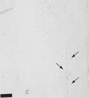
FIGURE 24-10 These really gross artifacts are caused by processor rollers that have not been cleaned. (Courtesy Cristl Thompson, El Paso Community College.)
The score of test objects counted on subsequent phantom images for each type of object should not decrease by more than 0.5.
The minimum number of objects required to pass ACR accreditation is four fibers, three speck groups, and three masses.
Test object images should be taken after equipment installation to determine the control values of the test objects for future comparison. Test object images also should be taken after the imaging equipment undergoes any maintenance.
When the test object image results in any of the factors exceeding the control values, the cause should be investigated and corrected as soon as possible. The test object images should always be viewed by the same person, on the same mammography viewbox, under the same viewing conditions, with the same type of magnifier that is used for mammograms and at the same time of day.
Monthly Tasks
The visual check (1) ensures that the imaging system lights, displays, and mechanical locks and that detents are functioning properly and (2) confirms the optimal level of the equipment’s mechanical rigidity and stability (Figure 24-11).
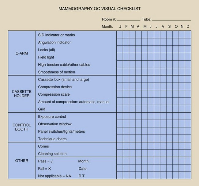
The mammographer should review all items on the list and should indicate the condition of each. If a particular piece of equipment has a feature that does not appear on the checklist, this feature should be added. This helps to ensure patient safety, high-quality images, and operator convenience. If any item on the list fails visual inspection, immediate steps should be taken to remedy the problem. The checklist should be dated and initialed.
Quarterly Tasks
This procedure is performed to determine the number and cause of repeated mammograms. Repeat analysis also identifies ways to improve efficiency, reduce costs, and reduce unnecessary patient dose. Such evaluations are valid only if patient volume results in at least 250 examinations.
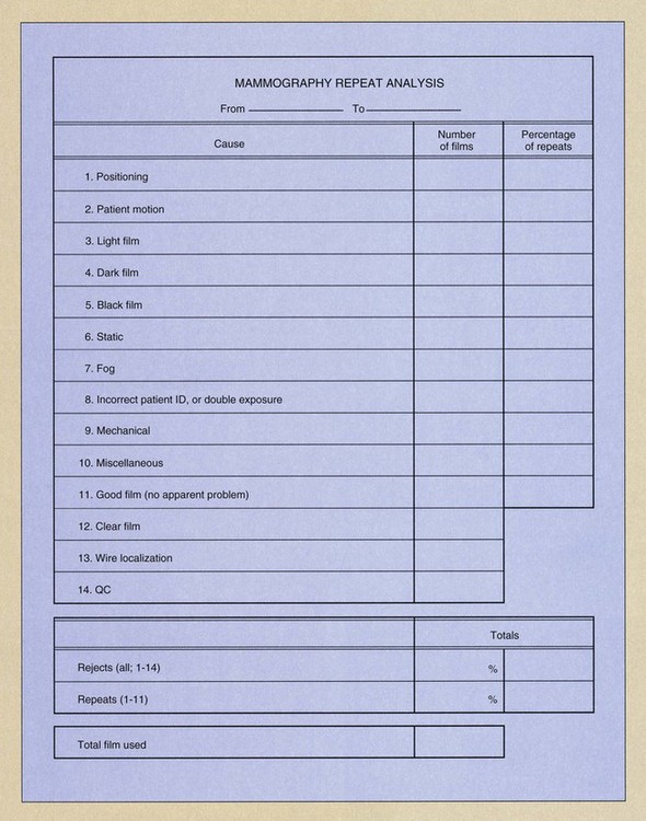
To begin the analysis, all presently rejected films should be discarded, so the analysis starts at zero. A complete inventory of the remaining film supply is taken, and all rejected films are collected for the next quarter. If the workload is low, the repeat analysis is continued until 250 patient examinations have been performed. Rejected films are sorted into different categories, such as poor positioning, patient motion, too light, and the other categories shown on the reject analysis form in Figure 24-12.
Next, the total number of films repeated and the total number of films exposed should be counted. The repeat rate is computed as follows:
 Repeat Analysis
The repeat rate for each category is determined by dividing the number of repeated films in a given category by the total number of repeats. The overall repeat rate should be less than 2%, as should the rate for each category. If overall rate is high or if a single category is higher than the others, the problem should be investigated. All repeated films should be included in the analysis—not only those rejected by the radiologist.

Analysis of Fixer Retention in Film
This task determines the amount of residual fixer in the processed film. The result is used as an indicator of archival quality.
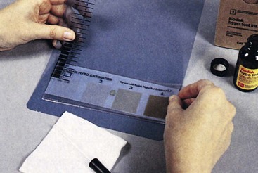
One sheet of unexposed film is processed. Next, one drop of residual hypo test solution should be placed on the emulsion side of the film and allowed to stand for 2 minutes. The excess solution should be blotted off and the stain compared with a hypo estimator, which comes with the test solution. A white sheet of paper should be used as the background.
The matching number from the hypo estimator should be recorded. The comparison should be made immediately after blotting because a prolonged delay allows the spot to darken.
The hypo estimator provides an estimate of the amount of residual hypo in grams per square meter. If the comparison results in an estimate of more than 0.05 g/m2, the test must be repeated. If elevated residual hypo is then indicated, the source of the problem should be investigated and corrected. Figure 24-13 shows the result from one such test.
Semiannual Tasks
Darkroom fog analysis ensures that darkroom safelights and other sources of light inside and outside the darkroom do not fog mammographic films. Fog results in loss of image contrast. This test also should be performed for a new darkroom and any time safelight bulbs or filters are changed.
Safelight filters should be checked to ensure that they are those recommended by the film manufacturer and that they are not faded or cracked. The wattage and distance of the bulbs from work surfaces also should be checked against the recommendations of the film manufacturer.
Next, all lights should be turned off for 5 minutes; this allows the eyes to adjust to the darkness. Then the door, passbox, processor, and ceiling should be checked for light leaks. Light leaks are often visible from only one perspective, so you may have to move around the darkroom.
If fluorescent lights are present, they should be turned on for at least 2 minutes and then turned off. A piece of film should then be loaded into the phantom cassette in total darkness. Then a phantom image should be taken as previously described. The film should be taken to the darkroom and placed emulsion side up on the countertop; one half of the image (left or right) should be covered with an opaque object. The safelights should then be turned on for 2 minutes with the half-covered film on the countertop.
After 2 minutes, the film should be processed and the OD measured very near both sides of the line separating the covered and uncovered portions of the film. The difference between the two ODs represents the amount of fog created by the safelights or by fluorescent light afterglow. This value should be recorded.
The level of this type of fog should not exceed 0.05 OD. Excessive fog levels should be investigated to find the source and take corrective action. The background OD (unfogged) of the phantom should be in the range specified previously (1.4–1.6).
Screen-Film Contact
Screen-film contact is evaluated to ensure that close contact is maintained between the screen and the film in each cassette. Poor screen-film contact results in image blur, again causing a loss of diagnostic information in the mammogram.
New cassettes should always be tested before they are placed into service. All cassettes and screens should be completely cleaned and allowed to air dry for at least 30 minutes before they are loaded with film for this test. After loading, the cassettes should be allowed to sit upright for 15 minutes to allow any trapped air to escape.
The cassette to be tested should be placed on top of the cassette holder assembly with the test tool placed directly on top of the cassette. An appropriate test tool is made of copper wire mesh with a grid density of at least 40 wires per inch (Figure 24-14). The compression paddle should be raised as high as possible. A manual technique of approximately 26 kVp should be selected; this results in an OD between 0.7 and 0.8 near the chest wall. Exposure time should be at least 500 ms.
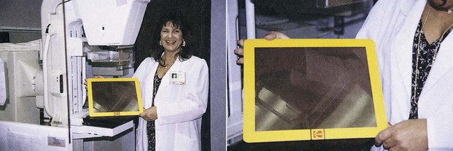
FIGURE 24-14 Wire mesh test tool for evaluating mammographic screen-film contact. (Courtesy Susan Sprinkle-Vincent, Advanced Health Education Center.)
A piece of acrylic should be placed between the x-ray tube and the cassette if the stated parameters cannot be met under normal circumstances. If acrylic is used, it should be placed as close as possible to the x-ray tube to reduce the scatter radiation that reaches the cassette.
The film should be processed regularly and viewed from a distance of at least 3 feet (90 cm). Dark areas on the film indicate poor screen-film contact (Figure 24-15). Any cassettes with poor screen-film contact should be cleaned and tested again. If poor contact persists at the same spot, the problem should be investigated and the cassette removed from service until the problem has been corrected.
Compression
Observation of compression ensures that the mammographic system can provide adequate compression in the manual and power-assisted modes for an adequate amount of time. This analysis also must show that the equipment does not allow excessive compression.
To check the compression device, a towel, tennis balls, or similar cushioning material is placed on the cassette holder assembly followed by a flat bathroom scale centered under the compression device. Another towel should be placed over the scale without covering the readout area (Figure 24-16). The compression device should be engaged automatically until it stops, the degree of compression should be recorded, and the device should then be released.
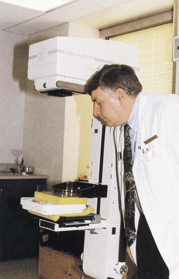
FIGURE 24-16 Testing breast compression with a conventional bathroom scale. (Courtesy Edward Nickoloff, Columbia University.)
The procedure should be repeated with the manual drive, again recording the compression. Never exceed 40 pounds of compression in the automatic mode. If such excess is possible, the equipment should be recalibrated, so 40 pounds of compression cannot be exceeded.
Both modes should be able to compress between 25 and 40 pounds and to hold this compression for at least 15 seconds. If either mode fails to reach these levels, the equipment should be adjusted properly. Use of the compression paddle is the reason for a lot of patient complaints, so it is sound practice to check this device and record the results.
Firm compression is absolutely necessary for high-quality mammography. Compression reduces the thickness of tissue that the x-rays must penetrate and thus reduces scatter radiation, resulting in increased image contrast at reduced patient dose. Compression improves spatial resolution by reducing focal-spot blur and patient motion. Finally, compression serves to make the thickness of the breast more uniform, resulting in a more uniform OD and making the image easier to read.
Nonroutine Tasks
When a new box of film must be opened and dedicated for processor QC, the old film must be crossed over, a very difficult and time-consuming activity. More detailed sources should be studied before this exercise is attempted.
Five strips from each of the old and new boxes of film should be exposed and processed at the same time. The OD should be read on each film for the three predetermined steps and the B+F. The five values for each of the old and the new set of films are then averaged for each of the predetermined steps.
The difference between the old and new values of MD, DD, and B+F should be determined and the control chart control values adjusted to the new values. If the B+F of the new film exceeds the B+F of the old film by more than 0.02, the cause should be investigated and remedied.
The use of strips exposed with the sensitometer longer than 1 or 2 hours before processing is unacceptable because these strips may be less sensitive to changes in the processor. The proper combination of film, processor, chemistry, developer temperature, immersion time, and replenishment rate should be used as recommended by the film manufacturer. QC also should be performed on the densitometer, sensitometer, and thermometer to maintain their proper calibrations. A log of these evaluations should be maintained.
Digital Quality Control
Quality control procedures for digital mammography (DM) are not universally prescribed as they are for screen-film mammography. The temporal routines associated with the darkroom, film processor, film, screens, and viewboxes are not encountered in DM.
The QC exercises associated with the mammography test object should be performed as described for screen-film mammography. Also, the visual checklist and repeat analysis should be performed as with screen-film mammography.
The repeat analysis requires more diligence because unacceptable images can be deleted. Properly, any unacceptable digital mammograms should be filed in a “Repeat Analysis” folder and evaluated for fault just as a screen-film mammogram. One measurable difference is that the repeat rate should be close to zero, certainly less than 1%. Improper radiographic technique can be a cause of screen-film repeat because of the image receptor response curve, the characteristic curve. Digital image receptors respond linearly to radiation dose and image contrast can be postprocessed (see Figures 16-6 and 17-15).
Screen-film mammography viewbox QC requires weekly attention. DM digital display devices must be evaluated daily using the protocols described in Chapter 22. This may be the most demanding digital QC chore.
Digital mammography imaging systems cannot be treated QC-wise as a general radiographic imaging system. Furthermore, there is no set protocol that can be applied to all dedicated DM imaging systems. The image receptor is different for various digital mammographic imaging systems and there are system-specific digital computer platforms containing QC analytical evaluations. Each vendor is required to develop appropriate QC tests and the QC mammographer is required to perform these tasks within the suggested schedule.
Table 24-2 identifies some of these tasks to be performed by QC mammographers. Similar and additional tasks are required annually of medical physicists.
TABLE 24-2
Elements of a Digital Mammographic Quality Control Program
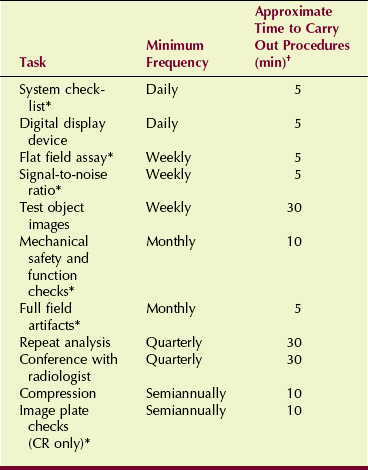
*Tasks specific to digital mammography
†Total annual time required for quality control: 86 hours.
Note that the time required of the QC mammographer for a digital system is nearly half that for a screen-film system. This represents another significant advantage of DM over screen-film mammography.
Summary
Quality control in mammography is part of an overall analysis and includes performance monitoring, record keeping, and evaluation of results. The three QC team members are the radiologist, who has specific duties of administration and tracking diagnostic results; the medical physicist, who examines and monitors the performance of imaging systems; and the QC mammographer, who performs many tests and evaluations involving imaging systems, film processing, and viewing mammographic images.
The many duties and responsibilities of QC mammographers are listed by time intervals. Daily routines for screen-film mammography include maintaining darkroom cleanliness and performing processor QC. Processor QC includes sensitometry and densitometry, as well as daily graphing of results.
Weekly routines include cleaning intensifying screens and viewbox illuminators, producing phantom images, and performing equipment checks.
Repeat analysis, based on at least 250 mammographic examinations, should occur four times a year. A repeat rate of less than 2% is required. Greater repeat rates should be investigated. Also, an archival check of film quality is performed quarterly.
Semiannually, the darkroom fog check is conducted and screen-film contact tests are performed. Finally, the compression test is done with the use of a bathroom scale under the compression paddle. Compression should never exceed 40 pounds of pressure. The automatic and manual modes should compress between 25 and 40 pounds of compression for 15 seconds.
Digital mammography QC routines are also time scheduled, and some such as repeat analysis and compression checks are similar to screen-film QC. However, many additional QC checks are vendor specific for each imaging system. Digital display devices require daily QC evaluation.
Annually, the medical physicist evaluates the mammography imaging system.
1. Define or otherwise identify the following:
2. List two aspects of the radiologist’s duties involving mammographic QC.
3. What is the most time-consuming task of QC mammographers?
4. Which member of the QC team tracks positive diagnoses?
5. Which member of the QC team should notice a temperature error in the developer solution?
6. What do the fibrils of the ACR accreditation test object simulate?
7. Describe how to clean radiographic intensifying screens. How often is this task performed?
8. Explain how mammographic viewboxes are different from conventional viewboxes.
9. Why are the QC tasks for digital mammography vendor specific?
10. What three objects are found in the ACR mammography test object?
11. Describe the process of scoring test objects.
12. How do you check for light leaks in the darkroom?
13. What is the acceptable fog value for 2 minutes of safelight exposure of film?
14. Describe the device used to check screen-film contact.
15. What is the maximum pressure allowed for the compression device?
16. Which should require more attention by the QC mammographer, screen-film or digital imaging?
17. What is the speed index, and how is it determined?
18. What is the minimum required luminance of a mammography viewbox?
19. When test object images are produced, what technique should be used?
The answers to the Challenge Questions can be found by logging on to our website at http://evolve.elsevier.com.