Hazards of the Anesthesia Delivery System
CIRCUIT PRESSURE AND VOLUME PROBLEMS
Insufficient Gas in the Breathing System
Failure to Initiate Artificial Ventilation
ANESTHETIC AGENT DOSAGE AND ADMINISTRATION PROBLEMS
Liquid Agent in the Fresh Gas Piping
Design of the Concentration Dial
Incorrect Filling of Vaporizers
Simultaneous Use of More Than One Vaporizer
Malignant Hyperthermia: Preparation for Susceptible Patients
Perspective
Failure of the anesthesia delivery system alone is a rare cause of anesthesia-related injury or death of a patient. More commonly, the delivery system is misused, the operator errs, or the delivery system fails in combination with the anesthesiologist being unaware that failure has taken place. In most cases of anesthesia machine failure, a temporal window of opportunity exists during which the anesthesiologist can detect the problem and correct it before the patient is harmed. Therefore a sound understanding of the anesthesia delivery system and the ways in which it can fail or be misused provides the basis for safe anesthesia practice.
Critical Incidents
The critical incident (CI) technique was first described by Flanagan in 19541 and was developed to reduce loss of military pilots and aircraft during training. It was modified and introduced into anesthesia by Cooper and colleagues,2 who interviewed staff and resident anesthesiologists in a large metropolitan teaching hospital. They collected and analyzed 1089 descriptions of CIs during anesthesia.3 A mishap was labeled a CI when it was clearly an occurrence that could have led, if not discovered or corrected in time, or did lead to an undesirable outcome, ranging from increased length of hospital stay to death or permanent disability. Other CI study inclusion criteria were that each incident involved an error by a member of the anesthesia team or failure of the anesthetist’s equipment to function properly; it occurred during patient care; it could be clearly described; and the incident was clearly preventable. Of the 1089 CIs, 70 represented errors or failures that had contributed in some way to a “substantive negative outcome” (SNO) defined as mortality, cardiac arrest, canceled operative procedure, or extended stay in the postanesthesia care unit (PACU), intensive care unit (ICU), or in the hospital. Although 30% of all CIs were related to equipment failures that included breathing circuit disconnections and misconnections, ventilator malfunctions, and gas flow-control errors, only three SNOs (4.3%) involved equipment failure, suggesting that human error was the predominant problem. Although equipment failures rarely cause death, CIs related to equipment are common and have prompted improvements in equipment design and construction and in system and patient monitoring.4
Many studies have demonstrated that anesthesia caregivers perform poorly when it comes to identifying problems with their anesthesia delivery systems. Buffington and colleagues5 intentionally created five faults in a standard anesthesia machine and then invited 190 attendees at a Postgraduate Assembly of the New York State Society of Anesthesiologists to identify them within 10 minutes. The average number of discovered faults was 2.2; 7.3% of participants found no faults, and only 3.4% found all five. The authors concluded that greater emphasis was needed in educational programs on the fundamentals of anesthesia machine design and detection of hazards.
In an effort to improve patient safety and ensure proper use of the anesthesia machine, the American Society of Anesthesiologists (ASA), the Anesthesia Patient Safety Foundation (APSF), and others support the use of checklists to enable the anesthesia practitioner to ensure that the anesthesia delivery system is functioning normally prior to the start of an anesthetic. In 1986, the U.S. Food and Drug Administration (FDA)—in cooperation with the ASA, machine experts, and manufacturers—published a generic apparatus checklist to enable the practitioner to check out anesthesia equipment thoroughly prior to use (see Chapter 32).6 March and Crowley7 evaluated the FDA recommended checklist and individual practitioner checklists in order to determine whether the existence of the FDA checklist would improve detection of anesthesia machine faults. Participants in this study were given machines with four faults that were detectable if the FDA checklist was used properly. The results of the study revealed that 25.8% of faults were found with the practitioner’s checklist, and 29.9% were found with the FDA checklist. In either case the results were poor and indicated that the mere introduction of the FDA checklist in 1986 did not improve the ability of these anesthesiologists to detect machine faults. However, it should be noted that in this study, no attempt was made to ensure that the FDA checklist was used properly during the checkout procedure.
Kumar and colleagues8 conducted a random inspection of 169 anesthesia machines and ancillary monitors in 45 hospitals in Iowa. The machines ranged in age between 1 and 28 years, the oldest being 1958 vintage. Five machines had no back-up source of oxygen, 60 had no functioning oxygen analyzer, 15 had gas leaks of greater than 500 mL/min (two proximal to the common gas outlet, 13 in the patient circuit). In addition, 14 of the 383 vaporizers tested did not meet the manufacturer’s calibration standards, and 20 had been added downstream of the machine common gas outlet. Of the 123 machines with ventilators, 16 had no alarm for low airway pressure, and only 31 had a high-pressure alarm. Of the ventilators surveyed, 59% were of the hanging bellows design; 41% had a standing bellows. Of these 123 machines, 95.5% had a scavenging system, but in 24.3% the scavenging circuit connectors were indistinguishable from the breathing circuit connectors, a potentially hazardous situation.7 The use of these old machines increases the risk for development of problems related to the delivery system; in addition, equipment users may not be as educated as they should be in their ability to detect such problems.
In 1993, the Australian Anaesthesia Patient Safety Foundation published results of the Australian Incident Monitoring Study (AIMS) that had collected information on 2000 CIs.9 Of these, 177 incidents (9%) were due to equipment failure in general, and 107 (60%) involved the anesthesia delivery system.10 Failures included problems with unidirectional valves, ventilator malfunctions, gas or electrical supplies, circuit integrity, vaporizers, absorbers, and pressure regulators. Concerning the problems with ventilation, it was recommended that critical areas be doubly or triply monitored and that monitoring equipment be self-activating.11
Adverse Outcomes
In the absence of mandatory reporting systems and concerns for litigation, it is difficult to accurately estimate the frequency of adverse outcomes associated with use of anesthesia delivery systems. Case vignettes have provided some insight into how adverse outcomes have arisen and led to development of standards for monitoring.12 The role of equipment failures leading to malpractice litigation in the United States has been studied by the ASA Closed Claims Project (CCP), a structured evaluation of adverse anesthetic outcomes obtained from the closed claims files of 35 U.S. professional liability insurance companies. A 1997 analysis of 3791 claims,13 of which 76% occurred during the period 1980 through 1990, found that gas delivery equipment problems accounted for 72 (2%) of 3791 claims. Of these 72, 39% were related to the breathing circuit, 17% to ventilators, 21% to vaporizers, 11% to gas tanks or lines, and 7% to the anesthesia machine. Death or brain damage occurred in 76% of the 72 cases. Initiating events were circuit misconnects, disconnects, and gas delivery system errors. The primary mechanism of injury was inadequate oxygenation in 50% of the claims, excessive airway pressure in 18%, and anesthetic overdose in 13%. Misuse was judged to have occurred in 75%, and equipment failure occurred in only 24%. Anesthesia caregivers were considered responsible in 70% of use error cases, and ancillary staff (e.g., technicians) were found to have contributed in 30%. Predominant mechanisms of injury were hypoxemia, excessive airway pressure, and anesthetic agent overdose. Overall, the reviewers deemed 78% of claims to have been preventable by better use of monitoring. Payment or settlements were made in 76% of the claims (median payment was $306,000; range, $542 to $6,337,000), and claims were notable for their high severity of injury, high cost, and prominent role of equipment misuse.
As of May 2012, the CCP database included 9536 claims, of which 115 were related to anesthesia gas delivery equipment.14 The most recent gas delivery system claim was for an event in 2003. Thus far, however, it appears that gas delivery equipment problems are decreasing as a proportion of total claims. Anesthesia gas delivery claims represented 4% of all claims from the l970s, 3% from the 1980s, 1% from the 1990s, and 1% from 2000 through 2010. Only 39 anesthesia gas delivery system claims were reported from 1990 through 2010. These include 4 supplemental oxygen line events, 7 anesthesia machine problems, 13 vaporizer problems, 5 ventilator problems, and 10 breathing circuit problems. The outcomes in anesthesia gas delivery equipment claims from 1990 through 2008 seem to be less severe than earlier claims. During that time, 38% of anesthesia gas delivery system claims resulted in severe injury or death, compared with 80% from 1970 through 1989 (P < .001). Among the 39 claims from 1990 through 2010 were 10 deaths, 5 cases of permanent brain damage, 6 cases of pneumothorax, and 9 awareness claims. Payments reflect the lower severity of injury, with a median payment (in 2011 dollars) of $199,000 in the 1990 through 2010 claims period compared with $802,750 (adjusted to 2011 dollars) for earlier gas delivery equipment claims. Thirty-two (82%) of the 39 post-1990 claims resulted in payment.
With patient safety as the primary concern, over the past several years, the basic gas machine has evolved into the present, more sophisticated anesthesia delivery system/workstation. The most current voluntary consensus standard describing the features of a modern machine is that published in 2000, and republished in 2005, by the American Society for Testing and Materials, ASTM F1850-00, which describes the requirements for anesthesia workstations and their components.15 This standard supersedes ASTM F1161-88, first published in 1988 and reapproved in 1994.16 It is anticipated that patient safety will be enhanced with the use of a state-of-the-art anesthesia gas delivery system together with adoption of the Standards for Basic Anesthetic Monitoring, first published by the ASA in 1986 and periodically updated.17 As in the case of monitoring standards, however, absolute confirmation may be difficult.
Complications
Complications caused by the anesthesia delivery system may be operator induced (misuse) or attributable to failure of a component. Issues with oxygen delivery and carbon dioxide elimination, circuit pressure and volume, inhaled anesthetic agent doses, humidification of inhaled gases, and electrical failure are discussed in detail here.
Hypoxemia
For the purposes of this chapter, hypoxemia is defined as an arterial partial pressure of oxygen (PaO2) less than 60 mm Hg, and it may be caused by problems with the anesthesia delivery system or by problems with the patient. If the patient is adequately ventilated, and the alveolar oxygen concentration is as expected, the problem is with the patient. Pulmonary conditions that cause shunting, venous admixture, ventilation/perfusion (V/Q) mismatch, or, less likely, diffusion defects can cause hypoxemia. Examples of these conditions are pneumonia, atelectasis, pulmonary edema, pneumothorax, hemothorax, pyothorax, pulmonary embolism, alveolar proteinosis, and bronchospasm. In addition, conditions that decrease mixed venous oxygen, such as anemia and shock, may also cause or contribute to hypoxemia (Box 30-1).
The anesthesia delivery system may cause hypoxemia by failing to deliver sufficient oxygen to the lungs, thereby reducing the alveolar oxygen concentration (Box 30-2). Inadequate ventilation, caused by either apnea or low minute ventilation, is a well-described cause of alveolar hypoxia. Problems can arise from failure to initiate manual or mechanical ventilation or from failure to recognize a major leak or disconnection in the breathing circuit, even though ventilation is attempted. The anesthesia delivery system may also cause hypoxemia by delivering insufficient oxygen from the machine to the breathing circuit.18
Insufficient or low inspired oxygen concentrations can be definitively detected via the use of an oxygen analyzer. The oxygen analyzer is a critical monitor, because although it may appear that pure oxygen is being delivered from the oxygen flowmeter, if the gas in the flowmeter is not oxygen, the patient will receive a hypoxic gas mixture.19 Without the oxygen analyzer, this condition would not be recognized. Although certainly a valuable patient monitor, the pulse oximeter does not replace the oxygen analyzer. A low oxygen saturation (SpO2) reading on a properly functioning pulse oximeter merely indicates that the patient’s hemoglobin is poorly saturated with oxygen. However, only the oxygen analyzer in the breathing circuit would be able to determine that the cause was inadequate delivery of oxygen to the patient. Therefore, these two monitors are complementary, and both must be used to ensure patient safety.
The oxygen analyzer is not without limitations. For it to act as a valuable safety device, it must have an adequate power source and be properly calibrated. In addition, it must be positioned such that it is sampling the gases that the patient will breathe. An analyzer placed by the inspiratory unidirectional valve may indicate a normal oxygen concentration, but if there is a disconnection between that point and the patient, the patient will not receive that gas. For this reason it is critical that the anesthesiologist understand the equipment design and the limitations of this device. The analyzer must function normally, the circuit valves must be present, the circuit must be intact, and the patient must be ventilated if the reading on the oxygen analyzer is to reflect the oxygen being delivered to the alveoli. Vigilant observation of patient ventilation, the integrity of the breathing system, and the oxygen analyzer ensure proper delivery of oxygen to the patient.
The gas entering the anesthesia machine from the hospital pipeline gas supply system or the oxygen cylinders may contain a gas other than oxygen. The central liquid oxygen reservoir may be filled with a gas other than oxygen (e.g., liquid nitrogen),20 or the pipelines throughout the hospital may be crossed, so that nitrous oxide or some other gas may be flowing through the oxygen pipeline.
Placement of a nitrous oxide wall adapter on one end of an oxygen hose would allow that hose to be connected to the wall’s nitrous oxide source and the anesthesia machine’s oxygen inlet, in which case nitrous oxide would flow through the oxygen flowmeter on the machine.21,22 During use of an anesthesia workstation, if it is suspected that a gas other than pure oxygen is being delivered via the pipeline, the pipeline hose must be disconnected, and the back-up oxygen tank must be opened. If the tank is opened but the pipeline remains connected, oxygen will not flow from the tank because of the difference in pressures between the pipeline (usually 55 psig) and the tank’s first-stage regulator (45 psig).
Most contemporary anesthesia workstations are equipped with an auxiliary oxygen flowmeter and oxygen outlet, for example, for connecting a nasal cannula. It must be recognized that no analysis of the gas flowing from this outlet exists, and it is presumed to be oxygen. In the event of a pipeline crossover, the hypoxic gas would also be delivered from the auxiliary oxygen flowmeter. Mudumbai and colleagues23 used medical simulation to investigate the response of 20 third-year anesthesia residents to an anesthesia machine pipeline crossover scenario. A significant number used the auxiliary oxygen flowmeter as a presumed external source of oxygen in their response to this crisis, which contributed to delays in definitive treatment.
In one case report, a modification of the gas-specific oxygen quick-connect on a wall outlet oxygen flowmeter allowed it to be connected to a nitrous oxide wall outlet. When a self-inflating resuscitation bag was connected to the wall outlet (presumed to be) oxygen flowmeter, in the course of resuscitating two patients, the anesthesia caregivers unknowingly delivered nitrous oxide with catastrophic outcomes.24 In the event that a gas presumed to be oxygen is being delivered in the absence of an oxygen analyzer, if the patient does not appear to be responding appropriately, the possibility of a wrong gas must always be considered, and the clinician should ventilate instead with room air.
Because of potential problems with the wall oxygen source, it has been suggested that only oxygen cylinders be used. However, this approach overlooks the possibility that an oxygen cylinder may be empty, the valve may be faulty, a tank key may not be available, or the tank may contain a gas other than oxygen.25,26 A nitrous oxide or other gas cylinder may be attached to the oxygen hanger yoke if the pin index system is defeated, either by removal of a pin or by placement of more than one washer between the yoke and the cylinder. Lorraway and colleagues27 studied a total of 20 second- and fourth-year anesthesia residents in a simulation of an oxygen pipeline supply failure. They found that the majority of participants either did not know how to change the oxygen cylinder or did not attempt it, even after prompting; this demonstrates an apparent basic deficiency in their training. Finally, crossed pipes within the anesthesia machine would allow a gas other than oxygen into the oxygen flowmeter.28 Delivery of a hypoxic gas via the oxygen pipeline or from a cylinder has been the basis for some now classic movies (e.g., “Green for Danger,” 1946; “Coma,” 1978).
Turning on the oxygen flow control valve may result in no oxygen gas flow.29 The hospital’s central oxygen system may be empty, shut down, or otherwise unavailable to deliver oxygen.30,31 In one report, separation of a brazed joint between the stainless steel liquid oxygen storage vessel and the brass pipe fitting connection to the hospital oxygen pipeline resulted in spillage of 8000 gallons of liquid oxygen into the atmosphere.32 Fortunately in this case, a bulk liquid oxygen storage tank in another location maintained the oxygen supply to the facility.
The oxygen hose to the anesthesia machine may become disconnected from the wall, and the back-up cylinders may be empty, absent, or turned off.33 The oxygen flow control valve or oxygen piping in the machine may be obstructed, thereby preventing the flow of oxygen to the flowmeter.34,35 In addition, the flowmeter bobbin or rotameter may become stuck, and it may appear that gas is flowing from that flowmeter even when it is not. Leaks in the oxygen flowmeter tube or in the low-pressure portion of the anesthesia machine can permit loss of oxygen before it reaches the common gas outlet of the machine.36-39
Contemporary anesthesia workstations are equipped with proportioning systems that prevent the delivery of a less than 25% oxygen mixture when nitrous oxide is being administered. Older anesthesia machines may not have these safety design features and should be considered obsolete. Because the oxygen fail-safe system is sensitive to the pressure, rather than the flow, of oxygen, it is possible on older anesthesia machines for the nitrous oxide flowmeter to be turned on without the oxygen flowmeter also being turned on (Fig. 30-1). This could lead to the delivery of a hypoxic gas mixture in the breathing circuit; the oxygen analyzer would detect this problem, and the anesthesiologist would have to recognize it and respond by adding oxygen to the mixture. Such a machine would, however, be considered unsafe per the ASA guidelines for determining anesthesia machine obsolescence.40
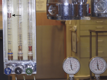
FIGURE 30-1 The fail-safe system (pressure sensor shutoff valve/oxygen failure protection device). The fail-safe system is pressure sensitive but not flow sensitive. Because the supply pressure of oxygen is adequate (2000 psig from the tank and therefore 45 psig in the machine), nitrous oxide may flow to its flowmeter and beyond at 4 L/min (arrow), even though the oxygen flow control valve is turned off and there is no flow of oxygen.
Although nitrous oxide–oxygen proportioning systems help to prevent the delivery of hypoxic mixtures, they are not foolproof and cannot be relied on entirely as the only method to prevent a hypoxic mixture. The Ohmeda Link-25 proportion limiting system (GE Healthcare, Waukesha, WI) causes the oxygen flow control valve to open further and increase flow if a hypoxic mixture would otherwise result when only oxygen and nitrous oxide are being used. This system can fail if the needle valve is broken in the closed position or if the linkage between the flowmeter controls fails.41,42 A limitation of all oxygen–nitrous oxide proportioning systems is that they do not analyze the gas flowing through the oxygen flowmeter, nor do they prevent administration of a hypoxic gas mixture if the machine has flowmeters for a third or fourth gas that is hypoxic (e.g., helium, carbon dioxide; Fig. 30-2).
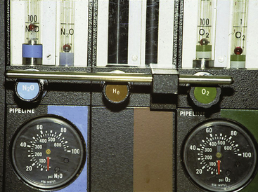
FIGURE 30-2 Three-gas anesthesia machine with flowmeter for helium. The proportioning system functions only between N2O and O2 flows. In addition, if a helium-oxygen mixture (75% He, 25% O2) were being administered and the helium tank were to become depleted, a hyperoxic mixture would be delivered to the patient circuit.
Abnormalities in the anesthesia breathing circuit can lead to a hypoxic mixture. Absent or incompetent unidirectional valves in the circle system will permit rebreathing of exhaled gas, which would present the patient with a hypoxic mixture if these gases were insufficiently mixed with fresh gas. In the Mapleson circuits (see Chapter 4), loss of the fresh gas supply from the machine leads to severe rebreathing of a hypoxic mixture as the patient uses up the oxygen and replaces it with carbon dioxide. Failure of the fresh gas supply in the circle system results in a breathing mixture that becomes progressively hypoxic, as the oxygen is consumed and only nitrous oxide remains.43-45
Leaks in the breathing circuit lead to loss of gases, especially during positive-pressure ventilation. If a hanging (descending) bellows ventilator is used, the lost gas may be replaced with entrained room air as the bellows descends by gravity during exhalation (Fig. 30-3). A standing bellows collapses if a significant leak develops in the breathing circuit. In addition, system leaks can lead to severe hypoventilation. The sources of leaks may be valve housings, circuit hoses, pressure monitoring and gas sampling lines, connection sites, pressure relief valves, and carbon dioxide absorbers. Leaks can also be caused by subatmospheric pressure being applied to the system from a scavenger suction or by a catheter that has unintentionally been passed into the trachea alongside the tracheal tube. A leak in the ventilator bellows might allow the drive gas in the ventilator bellows housing to enter the patient circuit. Depending on the gas used, this could affect the composition of the breathing mixture.46
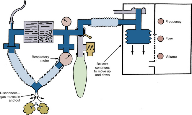
FIGURE 30-3 Hanging (descending) bellows ventilator. In the event of a disconnection, room air will be drawn into the circuit as the bellows fills during exhalation.
Closed-system or low-flow anesthesia can lead to the delivery of a hypoxic mixture. The total flow of gas is adjusted to compensate for the uptake of nitrous oxide and oxygen. However, if the oxygen content of the circuit gases is not carefully monitored, the uptake of nitrous oxide may be low, and that of oxygen may be high. The resultant mixture could become hypoxic.
Hyperoxia
Administration of a mixture that contains more oxygen than desired results in hyperoxia, which may be caused by insufficient nitrous oxide or air administered from the flowmeters; in addition, flowmeter leaks and inaccurate flowmeters may cause gases to be lost, with resultant high oxygen concentrations. A leak in a ventilator bellows that allows injection of pressurizing or drive-gas oxygen into the bellows (e.g., Datex-Ohmeda 7000, 7800, and 7900 series ventilators; GE Healthcare) may cause the inspired oxygen concentration to increase.47,48 Administration of helium and oxygen via separate flowmeters during laser surgery of the airway could be hazardous if the helium supply becomes depleted, or if the oxygen flush were operated, in which case a hyperoxic gas mixture would result that could lead to a fire (see Fig. 30-2).49
Hyperoxia may be undesirable or even dangerous in certain situations. It has been suggested that bleomycin induces sensitivity to oxygen toxicity and that the minimum fraction of inspired oxygen (FiO2) that can maintain an SpO2 of 90% or greater should be used in these patients.50 Similarly, when a fire risk is present, such as in airway or head and neck procedures, the FiO2 should be kept to the minimum compatible with an acceptable SpO2.51,52 In such situations, use of an oxygen analyzer with an appropriately set high oxygen concentration alarm is essential.
Hypercarbia
When carbon dioxide production exceeds elimination, the arterial carbon dioxide tension increases until an equilibrium is achieved. During anesthesia, patient factors or delivery system conditions may cause hypercarbia.
Patients breathing spontaneously are prone to hypercarbia because of the depressant effects of anesthetics on the central respiratory center, weakness from muscle relaxants, and motor blockade during spinal or epidural anesthesia. Complete or partial airway obstruction can cause hypercarbia. Pulmonary conditions that cause a large shunt and increased metabolic production of carbon dioxide without a concomitant increase in ventilation also cause hypercarbia.
The anesthesia delivery system can be a source of hypercarbia. Apnea caused by failure to ventilate either manually or mechanically raises the carbon dioxide concentration. Ventilating with an inadequate tidal volume or respiratory rate reduces alveolar ventilation and leads to hypercarbia. Leaks in the machine, circuit, and ventilator and failure to fill the bellows may also lead to hypoventilation (Box 30-3).
The anesthesia breathing circuit may contain insufficient gas if the pipeline gas source fails. However, this problem can be overcome by use of the reserve gas cylinders on the anesthesia machine. Inside the machine, leaks may develop either at the oxygen yoke or from a faulty check valve that permits gas to escape into the room. It is also possible for gas to leak from the pipes, flowmeters, vaporizers, vaporizer selector switches, and vaporizer mounts on the machine.
The interface hose from the anesthesia machine (common gas outlet) to the breathing circuit and the breathing circuit itself may be sources of a leak, and disconnections and leaks of sufficient magnitude lead to hypercarbia. Flow of gas from the machine to the circuit may be obstructed either in the machine or in the interface hose.53-56 Leaks in valve housings, tracheal tubes, ventilator hoses, reservoir bags, ventilator bellows, and system relief valves can reduce the volume in the breathing system and cause hypercarbia.57-60
Subatmospheric pressure applied to the breathing system can reduce the system volume and cause hypercarbia. Sources of subatmospheric pressure include vacuum hoses on scavenger interfaces, nasogastric tubes that have been placed in the trachea and suctioned, and sampling catheters from sidestream gas analysis systems (see Chapter 8).61
The anesthesia ventilator can cause hypercarbia if the settings are such that inadequate alveolar ventilation is provided. Either the rate may be too low or the tidal volume may be too small. On ventilators that allow the clinician to set the tidal volume, ventilatory rate, inspiratory-to-expiratory ratio, and flow of compressing gas independently of each other, smaller tidal volumes than desired may be delivered. The reason for this is that the ventilator may cycle to exhalation before the bellows is emptied completely; therefore it fails to deliver the preset volume to the patient. Factors that can cause this problem are high respiratory rate, low inspiratory/expiratory (I:E) ratio, low rate of inflow of the ventilator driving gas, and decreased pulmonary compliance. This problem can be discovered by careful observation of the ventilator bellows and monitoring of the exhaled tidal volume.
Poor pulmonary compliance also causes volume to be lost, because some of the tidal volume expands the compliant breathing circuit tubing. This “compression” volume is included in the tidal volume measured by a breathing system expiratory limb spirometer during exhalation, but it does not contribute to the alveolar ventilation. Pressure-preset ventilators may cycle to exhalation before an adequate tidal volume has been delivered. This also causes hypercarbia if it is unrecognized; therefore it is important to monitor the tidal volume and minute ventilation and not to assume that the volume set on the ventilator will in fact be delivered to the patient.
Fresh gas flows continuously from the anesthesia machine into the breathing system, but gas can leave the circuit only during exhalation. With older ventilator models used for anesthesia (e.g., Dräger AV-E [Dräger Medical, Telford, PA], Ohmeda 7000), the fresh gas entering the circuit during the inspiratory phase of ventilation is added to the tidal volume delivered by the ventilator, so that the patient receives a larger tidal volume than was set on the ventilator. These are described as tidal volume and I:E ratio change-uncompensated ventilators, in contrast to the more recent ventilator designs that use fresh gas decoupling or computerized compensation to ensure that changes in fresh gas flow (FGF), respiratory rate, or I:E ratio do not change the tidal volume that the patient receives. During use of an uncompensated ventilator, if the patient is normocarbic and the FGF is decreased, or if the I:E ratio is changed such that exhalation is prolonged, the result is a decreased tidal volume (less augmentation by the fresh gas inflow) and an increase in partial pressure of carbon dioxide (PaCO2; Fig. 30-4).62,63
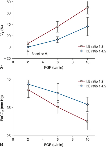
FIGURE 30-4 A, Effect of fresh gas flow (FGF) and inspiratory/expiratory (I:E) ratio on partial pressure of carbon dioxide (PaCO2) in patients during mechanical ventilation using an anesthesia ventilator with fixed-rate and bellows tidal volume. Note that as FGF increases, or the I:E ratio increases from 1:4.5 to 1:2, PaCO2 decreases. This is due to an increase in alveolar ventilation caused by an increase in tidal volume. Conversely, a decrease in FGF or I:E ratio results in an increase in PaCO2. The volume of gas added to the circuit during each inspiration is that exiting the ventilator bellows plus the FGF entering the circuit during inspiration (when the ventilator relief valve is closed). The latter volume is I /(I + E) × FGF/f, where f is the respiratory rate. Patient tidal volume, which determines alveolar ventilation and therefore PaCO2, is determined by the above formula, less gas compressed in the circuit during inspiration. This volume is calculated as circuit compliance times peak inspiratory pressure. B, Effect of FGF and I:E ratio on measured tidal volume (VT) during mechanical ventilation using an anesthesia ventilator at fixed rate and bellows tidal volume. As FGF or I:E ratio increases, the measured VT increases because during inspiration the fresh gas inflow is added to the delivered bellows tidal volume. All data are mean ± standard deviation. (From Scheller MS, Jones BR, Benumof JL: The influence of fresh gas flow and I:E ratio on tidal volume and PaCO2 in ventilated patients. J Cardiothoracic Anesth 1989;3:564.)
The carbon dioxide absorber may cause hypercarbia by providing a source of leaks from the circuit or by failing to absorb the carbon dioxide produced by the patient. The absorber may not be closed and sealed properly; improperly applied gaskets and absorbent granules on the gaskets can prevent the absorber canister from being sealed, and failure to close the handle on the absorber canister can also cause a huge leak.64 Exhausted granules and channeling of gas through the absorber prevent the absorption of carbon dioxide, which causes rebreathing of exhaled CO2 and hypercarbia. Machines equipped with absorber bypass switches can allow the exhaled carbon dioxide to be deliberately rebreathed. If this is not monitored carefully, the patient may become hypercarbic. Some contemporary workstations use detachable and disposable cartridges of CO2 absorbent. Removal of such a cartridge to facilitate buildup of CO2 at the end of a case is effectively the same as activating the absorber bypass switch on older machines (Fig. 30-5). The clinician must remember to replace the absorber cartridge in the circuit once the CO2 is as desired and before starting the next case.
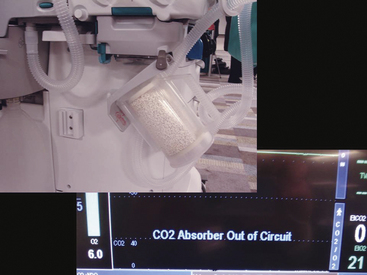
FIGURE 30-5 Removal of absorber cartridge, allowing carbon dioxide to build up in the breathing system. In this workstation a warning appears on the screen.
The color of the dye (e.g., ethyl violet) in the carbon dioxide absorbent indicates whether the absorbent has been exhausted. However, it has been noted that the ethyl violet indicator can be photodeactivated by fluorescent lights and can thereby give the false impression that the absorbent is fresh when it is in fact exhausted.65 Some anesthesia workstations are capable of controlled delivery of carbon dioxide (Fig. 30-6). Unintentional or improper use of the carbon dioxide flowmeter may cause hypercarbia.66-68
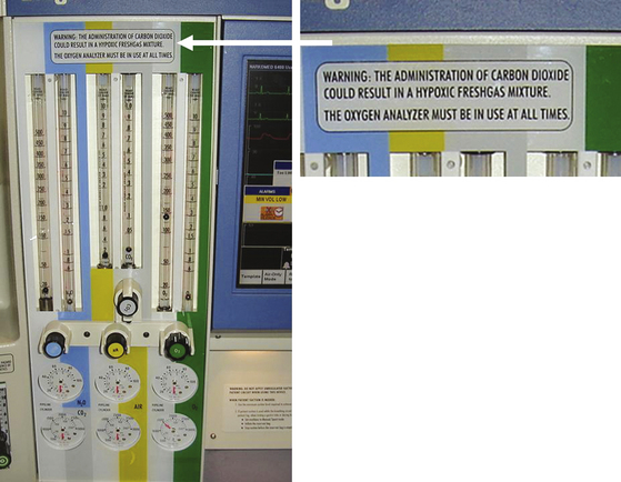
FIGURE 30-6 Anesthesia workstation with CO2 flowmeter. Note the warning label above the rotameter bank.
Hypercarbia has also been reported when an anesthesia machine nitrous oxide hose with an N2O quick-connect fitting was connected to a CO2 wall outlet in the operating room (OR). In this case the manufacturer-specific (Ohmeda) quick-connects for CO2 and N2O happened to be mirror images of one another, so that rotating the N2O hose connection through 180 degrees allowed it to be inserted into the CO2 wall outlet (Fig. 30-7).69
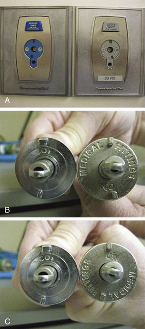
FIGURE 30-7 Ohmeda (GE Healthcare, Waukesha, WI) quick connectors for N2O and CO2 are mirror images of each other. A, Wall outlets. B, Hose connectors. C, Rotation of N2O connector through 180 degrees permitted connection to CO2 wall outlet. (From Ellett AE, Shields JC, Ifune C, Roa N, Vannucci A: A near miss: a nitrous oxide–carbon dioxide mix-up despite current safety standards. Anesthesiology 2009;110:1429.)
By increasing apparatus dead space, the anesthesia breathing circuit can increase dead space ventilation and act as a cause of hypercarbia. Specifically, the unidirectional inspiratory and expiratory valves may be absent or broken, or they may malfunction in the open position (Fig. 30-8). Large-volume tubes (e.g., “goosenecks”) placed between the Y-piece of the breathing circle and the airway increase apparatus (mechanical) dead space and may cause hypercarbia if compensatory ventilatory maneuvers (i.e., larger tidal volumes) are not used (Fig. 30-9).
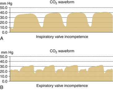
FIGURE 30-8 Incompetent unidirectional valves in a circle system. Capnograms from subject breathing from circle system. A, When inspiratory valve is incompetent. B, When expiratory valve is incompetent.
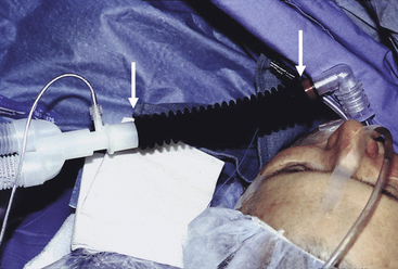
FIGURE 30-9 Insertion of “goose neck” connection between the Y-piece and a patient’s airway increases apparatus (mechanical) dead space.
The components of the circle breathing circuit must be arranged in such a way as to prevent rebreathing. Three arrangements of the circle system must be avoided: 1) the fresh gas inlet must not be placed between the patient and the expiratory unidirectional valve; 2) the adjustable pressure-limiting (APL, or “pop-off”) valve must not be placed between the patient and the inspiratory unidirectional valve; and 3) the reservoir bag must not be between the patient and the inspiratory or expiratory unidirectional valves.70
The Mapleson systems will permit the rebreathing of carbon dioxide, and hypercarbia will develop if appropriate precautions are not taken. For example, the Mapleson A circuit (the Magill attachment) should be used only with spontaneously breathing patients, and the FGF must be at least 0.7 times the minute ventilation. In addition, the hose between the patient and the reservoir bag must be long enough so that exhaled carbon dioxide does not reach the bag (Fig. 30-10).71
The Mapleson B and C systems always permit the rebreathing of exhaled carbon dioxide because exhaled gas is directed into a blind pouch. To prevent hypercarbia with these systems, FGFs of 1.5 to 2.5 times normal minute ventilation must be used, and the patient must be hyperventilated (see Fig. 30-10). If the patient is breathing spontaneously, the metabolic work performed increases. However, controlled ventilation with these circuits does not create this problem, because the work of breathing is not being performed by the patient.
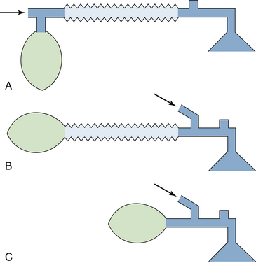
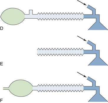
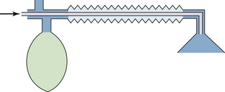
The T-piece systems—Mapleson D, E, and F—function similarly (Fig. 30-11). FGFs of 2.5 to 3 times minute ventilation prevent rebreathing at calculated normal minute ventilation. Alternatively, reduced FGFs can be used, but hypercarbia is prevented by hyperventilation. If the fresh gas connection is disrupted, hypercarbia will occur. This may be an especially difficult problem with the Bain circuit (coaxial Mapleson D), because the disconnected or kinked inner hose may go unnoticed (Fig. 30-12; see also Chapters 4 and 17).41,72-74
Hypocarbia
When carbon dioxide elimination exceeds production, PaCO2 decreases. When equilibrium between the two processes is achieved, a new steady state develops, and PaCO2 stabilizes. General anesthesia, neuromuscular blocking agents, and hypothermia reduce the metabolic rate. If minute ventilation is not decreased, the patient becomes hypocarbic. In addition, hyperventilation in general causes hypocarbia.
Hyperventilation and the resultant hypocarbia can be caused by simply having either the tidal volume, ventilatory rate, or both set too high. The FGF, which contributes to the minute ventilation in uncompensated ventilators (see above), will cause the patient to become hypocarbic if its contribution is not taken into account when the ventilator settings are chosen. In patients with very compliant lungs, the contribution of the FGF may be significant. The driving gas from the ventilator may increase ventilation if there is a hole in the bellows. This is more significant with the Dräger AV-E ventilator, because drive gas—a mixture of oxygen and entrained room air—flows into the bellows housing throughout the inspiratory time, whereas with the Datex-Ohmeda ventilators, the drive gas is oxygen, and drive-gas volume is determined by the set tidal volume. With the Dräger AV-E ventilator, drive gas that enters the breathing circuit via a hole in the bellows increases the volume of gas delivered to the patient and also affects the composition of the circuit gases. The result is hyperventilation of the patient’s lungs with an unintended gas mixture.
Circuit Pressure and Volume Problems
Essential to anesthesia delivery, oxygenation, and ventilation of the patient is adequate movement of gases between the delivery system and the patient’s lungs. Four basic causes of failure of this function have been described by Schreiber18 and include 1) occlusion in the ventilatory pathway, inspiratory or expiratory; 2) insufficient gas in the breathing system; 3) failure to initiate artificial ventilation when required; and 4) disconnection in the breathing system during mechanical ventilation.
Occlusions
The anesthesia circle breathing system is composed of a number of tubes that may become occluded.75 In general, the cause of such occlusions can be found outside the tube, within the wall, or within the lumen of the tube. Tubing misconnections have become less common since the introduction of standard diameters; however, if adapters are used, misconnections are still possible. By standard, breathing circuit tubing connections are 22 mm in diameter, waste gas scavenging tubing is 19 or 30 mm in diameter, and the common gas outlet and tracheal tube connectors are 15 mm in diameter. Accessories added to the circuit may cause an obstruction to the gas pathway. Filters placed in the circuit, incorrectly connected humidifiers, manufacturing defects in tubing, and failure to completely remove plastic wrapping from breathing system components before connecting them into the circuit have all been reported as causes of total occlusion of the breathing circuit (Fig. 30-13).76-80
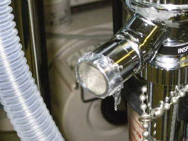
FIGURE 30-13 Disposable circuit with plastic packaging intact. Plastic that is not removed before connecting the circuit to the inspiratory port on the absorber canister would cause complete obstruction to inspiration.
A freestanding positive end-expiratory pressure (PEEP) valve may cause obstruction if it is placed in the inspiratory limb of a circle system. The PEEP valves that use a weighted ball, such as those made by the Boehringer Company (Wynnewood, PA), are designed to be mounted vertically on the expiratory side of a circle system. In one case, the weighted-ball PEEP valve was erroneously placed horizontally and was reversed in the expiratory limb between the circuit and the exhalation unidirectional valve. When the oxygen flush was operated, the metal ball was driven downstream, totally obstructing the PEEP valve and circuit, preventing exhalation, and causing increased intrathoracic pressure. In another case, the PEEP valve was placed on the inspiratory side in reversed fashion; this caused total obstruction on the inspiratory side of the circuit and prevented inspiration (Fig. 30-14).81 Because of such potentially fatal errors, freestanding PEEP valves must be used with great caution, if they must be used at all. Freestanding bidirectional PEEP valves are safer, because incorrect placement will not cause total breathing circuit obstruction.82
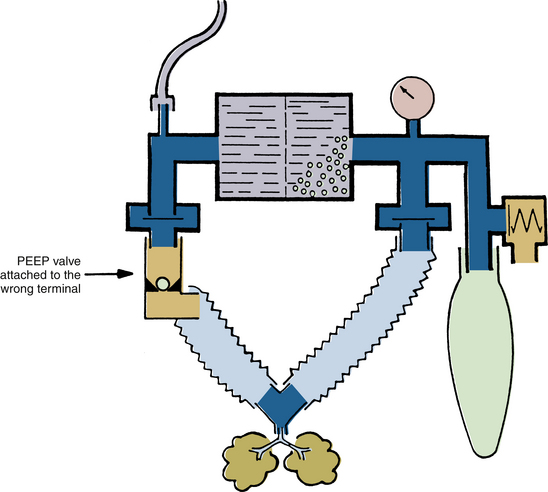
FIGURE 30-14 Erroneous insertion of positive end-expiratory pressure (PEEP) valve on inspiratory port causes complete obstruction to inspiration.
Although total occlusion of the breathing circuit should activate a pressure or volume alarm in most cases, depending on the system used, these alarms may be fooled when the tracheal tube is totally occluded. Consider a breathing circuit with a pressure-monitoring system that incorporates a fixed setting of +65 cm H2O for the high-pressure alarm limit threshold, such as that used on some older anesthesia machines. When the tracheal tube becomes totally obstructed because of a kink or total intraluminal obstruction, the pressure rises in the circuit, which satisfies the low-pressure alarm. However, unless the pressure reaches +65 cm H2O, the high-pressure alarm is not activated. The peak pressure achieved in the circuit during inspiration depends on the inspiratory flow control setting, which determines the driving pressure available to compress the bellows, the preset tidal volume, the inspiratory time, and the fresh gas inflow rate from the anesthesia machine. At low ventilator inspiratory flow settings, the driving pressure of the ventilator may be 50 cm H2O or less; when combined with normal rates of fresh gas inflow from the machine, this may result in failure of the peak inspiratory pressure to reach the high-pressure alarm threshold of +65 cm H2O. During exhalation, excess gas is released normally from the patient circuit. The volume alarm may also be fooled in this situation, depending on its low-limit threshold setting. In the system described, the low-volume alarm threshold was fixed at 80 mL. The situation described above involved total failure to ventilate the patient and resulted in an adverse outcome.12 In contemporary practice this should be immediately detectable by continuous capnometry by pressure and volume alarms whose thresholds can be set close to the normal values for that particular patient. An appropriately set high-pressure limit on the ventilator should prevent an adverse outcome in such a situation.
Misconnections and obstructions should be preventable and may be detected by testing of the breathing circuit before use; this should be done with all accessories in place and in spontaneous, assisted, and controlled ventilation modes. These procedures are described in the recommended preuse checkout. Occasionally, however, an obstruction can develop because of failure of a component during the case, so there is no substitute for monitoring and vigilance.83
Insufficient Gas in the Breathing System
An insufficient volume of gas in the breathing system may be caused by inadequate delivery or excessive loss. Inadequate delivery may be due to failure of gas delivery to the machine or from the common gas outlet.84 A decrease in oxygen supply pressure to the machine may cause a decrease in gas flows set at the flowmeters, and flow setting errors may also occur. A disconnection, misconnection, or obstruction between the machine’s common gas outlet and the patient circuit have a similar effect.
An inadequate volume of gas in the circuit may also be caused by excessive removal. An active waste-gas scavenging system uses wall suction to remove waste gases from the scavenging interface. Excess negative pressure may be applied to the circuit if the negative-pressure relief (“pop-in”) valve or valves on the interface should become occluded.85 A similar situation can arise with an open-reservoir scavenging system if the relief ports become occluded while suction is applied to the interface. A high subatmospheric pressure in the scavenging system may open the circuit APL valve, transmitting the subatmospheric pressure to the patient circuit. If a ventilator were being used, unrelieved excess negative pressure in the scavenging system would in most cases tend to hold the ventilator pressure relief valve to its seat, preventing its opening on exhalation and causing high pressure to develop in the circuit (Fig. 30-15).
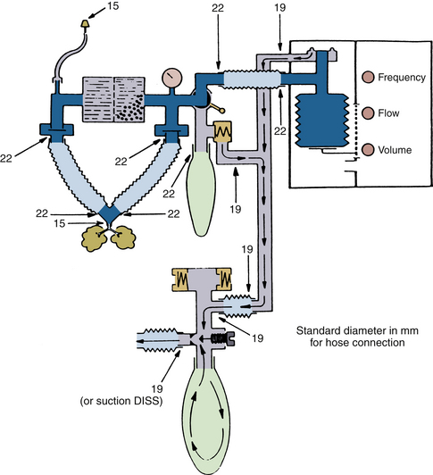
FIGURE 30-15 Diameters (in millimeters) for hose terminals in the anesthesia breathing and scavenger systems. Unrelieved subatmospheric pressure from the scavenger system can be applied directly to the patient circuit through the adjustable pressure-limiting valve. This creates subatmospheric pressure in the breathing circuit and, consequently, in the lungs. DISS, diameter index safety system (connector). (From Schreiber P: Safety guidelines for anesthesia systems, Telford, PA, 1985, Dräger Medical.)
A sidestream-sampling (diverting) gas analyzer connected to the patient circuit has been reported as the cause of excessive negative pressure in a breathing circuit, where the FGF of 50 mL/min during cardiopulmonary bypass was less than the analyzer’s gas sampling rate of 250 mL/min.61 The gas sampling rates of commonly used sidestream-sampling gas analyzers vary between about 50 mL/min and 300 mL/min. Although the potential for creating negative pressure in the circuit exists if low FGF rates are being used, contemporary analyzers are designed to sound an alarm and limit the negative pressure that can be generated.
Excess gas removal by a sampling device during spontaneous ventilation creates a subatmospheric pressure in the circuit that in turn causes the APL valve to close. This prevents the scavenging system negative-pressure relief valve or valves from relieving the negative pressure in the circuit. In one study, albeit from 1987, the maximum circuit subatmospheric pressure achieved by sidestream-sampling devices during testing ranged from −1 to −148 mm Hg.61 If transmitted to the patient’s airway, such low pressures have the potential to cause negative-pressure barotrauma and cardiovascular dysfunction.
Excessive volume loss resulting in negative pressures in the breathing system may arise if hospital suction is applied through the working channel of a fiberoptic bronchoscope that has been inserted into the circuit through an airway diaphragm adapter; this can also occur with a suction catheter that has been accidentally advanced alongside the tracheal tube into the trachea.
Inadequate circuit volume and negative pressure may occur during spontaneous ventilation in the presence of a low FGF rate and inadequate size of reservoir bag, such as a pediatric size used with an adult patient. During inspiration, the reservoir bag will collapse, and a negative pressure will be created in the circuit. Circuit APL valves usually have a minimum opening pressure that is slightly greater than that needed to distend the reservoir bag. If the bag were the correct size but noncompliant, or if the APL valve were to have a low opening pressure, most of the gas would exit through the APL valve during exhalation rather than fill the bag. The net result would be an inadequate reservoir volume for the next inspiration. Modern circuit pressure monitors incorporate a subatmospheric pressure alarm such that when pressure is less than −10 cm H2O at any time, audible and visual alarms are triggered.
Failure to Initiate Artificial Ventilation
Failure to initiate artificial ventilation is usually attributable to an operator error. The error may be a failure to turn on the ventilator, for example, after tracheal intubation or separation from cardiopulmonary bypass; unintentionally setting a respiratory rate of zero breaths/min; failure to select the “automatic” (ventilator) setting on the manual/automatic selector switch in the circuit; or failure to connect the ventilator circuit hose, either at the patient circuit connector by the selector switch or at the bag mount. Because some older circuit volume and pressure alarms must be deliberately enabled or are enabled only when the ventilator is on, these monitors will fail to detect that the ventilator has not been turned on. In this respect, continuous capnography provides the most sensitive monitor of ventilation. If the delivery system incorporates a standing-bellows ventilator, failure to connect the ventilator tubing to the circuit will cause the bellows to collapse.
With either a standing or hanging bellows design, when a ventilator is turned on but the “manual” (bag) mode is selected at the selector switch, the bellows will attempt to empty during inspiration against a total obstruction—the closed selector switch—and its failure to empty will be readily observed. Failure to ventilate in this situation is sounded by both low pressure and volume alarms in the breathing system. Some older designs of circle system lack a manual/automatic selector switch, and the APL valve must be closed to effect intermittent positive-pressure ventilation (IPPV) when the ventilator hose is connected to the bag mount. In such a case, failure to close the APL valve is yet another cause of failure to initiate IPPV.
Even if the breathing system incorporates a selector switch, there are occasions when the primary anesthesia ventilator fails, and a freestanding ventilator may be brought in to provide IPPV. The foregoing considerations apply if the new ventilator is connected to the circuit via the bag-mount connection; that is, the “manual” mode is selected, and the APL valve is closed.
Leaks and Disconnections in the Breathing System
Breathing circuit disconnections and leaks are among the most common causes of anesthesia mishaps.3,13 Anesthesia breathing systems contain numerous basic connections, and as more monitors, humidifiers, filters, and gas flow and gas sampling adapters are added, additional connections are needed. Each connection is a potential disconnection. Disconnections cannot be totally prevented; in the past, some have considered the 15-mm connector between the tracheal tube and the circuit to be a “safety fuse” to prevent unintentional extubation, although most now prefer a secure system that does not disconnect. Circuit disconnections and their detection have been the subject of several reviews.86 Cooper and colleagues2 found that disconnections of the patient from the machine were responsible for 7.5% of critical incidents involving human error or equipment failure. Of these disconnections, about 70% occured at the Y-piece.2,87
The risks of disconnection are reduced by secure locking of connecting components; use of disconnect alarms (pressure, volume, and capnography); and, most importantly, user education. Making secure friction connections, such as those between the tracheal tube and elbow adapter or between the adapter and the Y-piece, requires that the clinician use a pushing and twisting motion rather than merely pushing the two units together. When a disconnection occurs, the anesthesiologist must systematically trace the flow of gases through the breathing system, looking for the disconnection in the same way as would be done in the event of an obstruction situation or no gas flow.
Most disconnections are detectable by the basic breathing system monitors of pressure, volume, and flow. Pressure monitors sound an alarm if the peak inspiratory pressure in the circuit fails to reach the threshold low setting. The alarm setting on the monitor should be user adjustable, and the user should be able to set it to a level just below the usual peak inspiratory pressure. Most monitors now provide a continuous graphic display of the circuit pressure and alarm threshold or thresholds. A response algorithm for the low-pressure alarm condition has been proposed (Fig. 30-16).88
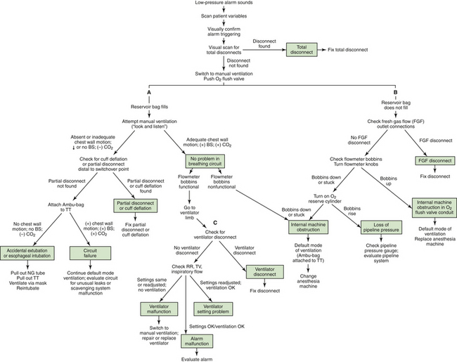
FIGURE 30-16 Response algorithm for a low-pressure alarm condition. The three limbs of the algorithm are the breathing circuit limb (A), the fresh gas flow (FGF) limb (B), and the ventilator limb (C). BS, breath sounds; NG, nasograstric; RR, respiratory rate; TT, tracheal tube; TV, tidal volume. (From Raphael DT, Weller RS, Doran DJ: A response algorithm for the low-pressure alarm condition. Anesth Analg 1988;67:876-883. Reproduced by permission of the International Anesthesia Research Society.)
The breathing circuit low-pressure alarm can be “fooled” if it is not set at the correct sensitivity. Thus a circuit disconnection at the Y-piece combined with sufficient resistance at the patient-connector end may not trigger the low-pressure alarm if inspiratory gas flow from the ventilator bellows is high enough for the pressure to cross the low-pressure alarm threshold. Examples include unintended extubation of a patient who has a small-diameter tracheal tube, in which case the tube connector offers a high resistance to gas flow, and occlusion of the open patient connector by the surgical drapes. A circuit low-pressure alarm sensing pressure in the absorber may be fooled in the presence of high resistance between the inspiratory tubing connector and the Y-piece, such as may be attributable to a cascade humidifier in the inspiratory limb of the circle.89 Humidifiers may also represent the source of a detectable leak in the anesthesia circuit.
A breathing circuit low-pressure alarm is less likely to be fooled when a standing bellows ventilator is being used, because failure of the bellows to fill adequately during exhalation will lead to lower peak pressures on the next inspiration (Fig. 30-17). With the hanging bellows design, the peak inspiratory pressure with a disconnect tends to be higher than with a standing bellows ventilator disconnect, the hanging bellows having filled completely during exhalation. A pressure alarm set to an inappropriately low threshold is therefore more likely to be fooled by a hanging bellows ventilator.
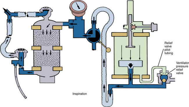
FIGURE 30-17 AV-E standing bellows ventilator in inspiratory cycle. When a disconnect in the breathing circuit occurs with the standing bellows ventilator, the bellows falls and does not reexpand until the circuit is made gas tight again. (Courtesy Dräger Medical, Telford, PA.)
The common gas outlet of the anesthesia machine was a site of disconnections before the standard use of retaining devices. The diameter of the tubing connecting the common gas outlet with the circuit is relatively narrow and offers relatively high resistance to gas flow compared with the 22 mm diameter circuit tubing. If a hanging-bellows ventilator were being used with a large tidal volume setting, the machine-to-circuit connector tubing resistance may be such that during inspiration, the low-pressure alarm limit would be exceeded despite the leak.90 During exhalation, room air would be entrained via the fresh gas inflow tubing to refill the bellows (see Fig. 30-3). A disconnection of this tubing may also lead to a hypoxic gas mixture in the circuit, as air is entrained and oxygen is consumed. Detection of this type of disconnection, which is associated with air entrainment, is aided by an oxygen analyzer with an appropriately set low concentration alarm threshold located in the patient circuit.
If the circuit low-pressure alarm has been set as recommended, to just below the peak inspiratory pressure, it should be recognized that more false-positive alarms will be generated. Thus, when a tidal volume–uncompensated ventilator is used with a set tidal volume, a decrease in FGF, I:E ratio, or inspiratory flow rate or an increase in respiratory rate will decrease the peak inspiratory pressure and thereby trigger the alarm. However, a false-positive alarm with an appropriate response is preferable to failing to detect a potentially hazardous situation, provided that the user does not permanently silence the alarm.
Leaks from the breathing circuit, other than those attributable to component disconnection, may also result in inadequate exchange of gas between the system and patient. Leaks may arise in any component because of cracking, incorrect assembly, or malfunction of a system component, particularly the ventilator pressure relief valve.91 Sometimes the design of a component may make a leak more likely. In the Fabius and Apollo workstations (Dräger Medical), lifting the APL valve allows gas to leave the circuit. Several incidents of tubing becoming trapped under the APL valve that resulted in a leak and failure to ventilate have been reported.92-95 As a result the APL valve has been redesigned, and for those machines with the older design, an upgrade is available.
During inspiration, the ventilator pressure relief valve is normally held closed by the pressure of the driving gas from the bellows housing. If this valve is not held closed during inspiration, gas in the patient circuit may be vented to the scavenging system rather than going to the patient. Incompetence of the ventilator pressure relief valve has been reported in connection with pilot-line disconnection or occlusion and valve damage.96 In such a situation, the loss of volume from the circuit would be detected by appropriately set pressure and volume alarms, but the source of the leak might be less obvious. If a closed-reservoir scavenging system is in use, the diagnosis is made by observation of the scavenging system reservoir bag. The bag normally fills during exhalation, as gas is released from the patient circuit, and it empties during inspiration, when the ventilator pressure relief valve is closed. If the ventilator pressure relief valve is incompetent, the scavenging system reservoir bag will be seen to fill during the inspiration, as the ventilator bellows empties its contained gas into the scavenging system.
Leaks and malfunctions in the patient circuit are sometimes first detected by an airway gas monitor, when the composition of the gas mixture in the breathing system deviates significantly from that expected. Application of negative pressure to the circuit by a malfunctioning scavenging system, or intermittently by a hanging bellows or piston ventilator during exhalation, may cause entrainment of air into the breathing system through a small leak otherwise unrecognized by pressure, volume, or even carbon dioxide monitoring.97,98 A leak of room air or other gases into the patient circuit can result in dilution of the anesthesia gas mixture and has the potential, in an extreme case, to induce awareness under anesthesia.99 Leaks into the patient circuit may occur if there is a hole in the ventilator bellows. In this case, the high pressure in the driving-gas circuit forces driving gas into the patient circuit during inspiration. With GE Healthcare ventilators, the diluting gas is normally 100% oxygen; but with a Dräger AV-E, it is a mixture of air and oxygen.100,101 Such an event might be detected by a change in FiO2, peak inspiratory pressure, tidal or minute volume, or end-tidal carbon dioxide or with a multigas or agent analyzer.
High Pressure in the Breathing System
The anesthesia machine provides a continuous flow of gas to the patient circuit. Whenever circuit gas inflow rate exceeds outflow rate, excessive pressures can develop. If these pressures are transmitted to the patient’s lungs, severe cardiovascular compromise, barotrauma, and even pneumothorax may arise.102,103
During spontaneous ventilation, high pressure may be caused by 1) inadequate opening, or even complete closure, of the APL valve; 2) kinking or occlusion of the tubing between the APL valve and the scavenging interface; or 3) malfunction of the interface positive-pressure relief valve. During spontaneous ventilation, the bag will distend to accommodate the excess gas. Reservoir bags are highly distensible and limit the maximum circuit pressure to approximately 45 cm H2O. Nevertheless, such an airway pressure could produce hypotension by inhibiting venous return. Increases in circuit pressure will be more rapid when the fresh gas inflow rate is high; for example, during prolonged use of the oxygen flush.104
Excessive pressure in the circuit may occur during use of an anesthesia ventilator. During inspiration, the ventilator pressure relief valve is normally held closed (see Fig. 30-17). Thus a high inspiratory gas-flow rate will be associated with increased peak pressures in the circuit. To protect the patient’s lungs from excessive pressure, all contemporary ventilators incorporate a high-pressure alarm and high-pressure limit.
There are many reports of ventilator malfunctions causing excessive circuit pressures. Failure of the ventilator to cycle from inspiration to expiration results in driving gas continuing to enter the bellows housing (Dräger Medical), or it causes gas to enter but not leave (Datex-Ohmeda). This causes the ventilator pressure relief valve to remain closed, and excess pressure build ups within the circuit. The pressure increase is limited by the driving-gas pressure prevailing in the bellows housing.105 In Dräger AV-E ventilators, this pressure depends on the setting of the inspiratory flow-control knob. Other reported causes of the ventilator pressure relief valve failing to open normally include mechanical obstruction of the driving-gas exhaust system (e.g., blocked Dräger AV-E muffler),106 kinking of a Dräger AV-E ventilator pressure relief valve pilot line during inspiration, failure of a solenoid valve causing persistent inhalation, and diffusion of nitrous oxide into the space between the two pieces of rubber constituting the relief valve diaphragm, causing insidious PEEP.107 Even with normal ventilator bellows function, high pressures in the circuit may be caused by occlusion of the tubing between the ventilator pressure relief valve outlet and the scavenging system or by obstruction of the scavenging interface positive-pressure relief valve. In such cases, as the pressure in the patient circuit rises, the ventilator bellows empties less completely and may even become distorted.
High pressures arising in the circuit are detected by the circuit pressure monitor, which incorporates two types of alarms: a continuing-pressure alarm is annunciated usually when the circuit pressure remains in excess of +15 cm H2O for more than 10 seconds, and a high-pressure alarm is annunciated when the circuit pressure exceeds the high-pressure threshold limit, which in contemporary monitors is set by the user but often has a default setting of +40 cm H2O, depending on the unit. When either of these alarms is annunciated during mechanical ventilation, a problem should be suspected with the ventilator circuit. In the absence of a high-pressure limit feature, circuit pressure can be immediately relieved by disconnection of the patient from the circuit at the Y-piece, inspiratory hose, or expiratory hoses or by selecting the manual (bag) mode and relieving pressure by opening the APL valve. The incorporation of safety relief valves into the circuit as a protection against high pressures is now the norm, and the opening threshold is set usually to about 5 cm H2O above peak inspiratory pressure. The pressure limit must be set according to the patient, because too low a setting may preclude the ability to ventilate a patient with poor total thoracic compliance.
Pressure-limiting devices differ among some of the older model ventilators. The Datex-Ohmeda 7800 series ventilators incorporate an inspiratory high-pressure limit such that when the selected threshold is exceeded (the pressure measured in the patient circuit downstream of the inspiratory unidirectional valve), the ventilator cycles to expiration, driving-gas circuit pressure falls to zero, and excess patient-circuit gas is discharged to the scavenging system via the ventilator pressure relief valve. The basic model Dräger AV-E ventilators were not pressure limited, but a pressure-limit control is available and may be retrofitted to certain standing bellows–design AV-E units.108 The Dräger AV-E pressure-limit control device senses the pressure in the patient circuit at the bellows, and whenever the threshold high-pressure limit is exceeded, a valve opens in the driving-gas circuit (bellows housing) to release excess driving gas to the atmosphere, thereby limiting driving-gas pressure such that patient circuit pressure does not exceed the set limit for the remainder of the inspiration. The time cycling (I:E ratio and set ventilatory rate) of the Dräger AV-E is therefore maintained, in contrast to the Datex-Ohmeda 7000/7800 series ventilators.109 Both the Dräger AV-E and Datex-Ohmeda approaches to limiting pressure in the patient circuit require a normally functioning ventilator pressure relief valve, because it is through this valve, the opening pressure of which is controlled by the pressure in the driving-gas circuit, that excess gas and pressure is relieved from the patient circuit. If the pressure relief valve or its outflow path should become obstructed, neither the Dräger AV-E nor the Datex-Ohmeda pressure-limiting mechanisms would be effective in relieving pressure in the patient circuit.
Anesthetic Agent Dosage and Administration Problems
Adverse outcomes may arise as a result of an anesthetic agent overdosage or underdosage or administration of an incorrect agent. Hazards of vaporizer malfunction causing anesthetic overdosage or underdosage are caused by incorrect handling, incorrect agent use, human error, and, rarely, internal breakdown of the vaporizer itself.
Liquid Agent in the Fresh Gas Piping
Lethal anesthetic agent overdosage may occur when excessive amounts of saturated vapor or even liquid agent enter 1) the bypass portion of the vaporizer, 2) the machine piping between the vaporizer and the common gas outlet, 3) the interface hose, or 4) the breathing circuit.110 The overdosage situation was more likely when measured-flow vaporizers (Copper Kettle [Puritan-Bennett; Covidien, Mansfield, MA], Verni-Trol [Ohio Medical Products, Gurnee, IL]) were used because calculation or flow-setting errors could easily arise. In addition, some older designs of vaporizers could be overfilled, so that excess liquid could enter the fresh gas piping. Fortunately, measured-flow systems are no longer in use and are considered obsolete. Modern vaporizers are concentration calibrated and are designed to prevent overfilling (see also Chapter 3).
Tilting or tipping of a vaporizer may cause liquid agent to enter the bypass of the vaporizer or the machine piping. One milliliter of liquid potent volatile agent produces approximately 200 mL of vapor at 20° C (see Chapter 3). For example, if 1 mL of liquid isoflurane were to enter the common gas piping, it would require approximately 20 L of fresh gas to dilute the resulting vapor to a concentration of 1%, or a minimum alveolar concentration (MAC) of approximately 0.8. It is easy to appreciate how a relatively small volume of liquid agent in the wrong place could have a profound effect on a patient.
If a vaporizer has been tilted or tipped, and there is concern that liquid agent may have leaked into the piping of the machine, then with no patient connected to the system, the vaporizer should be drained and then flushed with a high flow rate of oxygen from the anesthesia machine flowmeter (not the oxygen flush, which bypasses the vaporizer); the vaporizer dial should be set to a high concentration during this procedure.111,112 If any doubt still exists as to the safe function of the vaporizer, it must be withdrawn from clinical service until certified safe for use by an authorized service representative. Additional caution is needed with a halothane vaporizer that has been tipped. Liquid halothane contains thymol, a sticky preservative that does not evaporate. Thymol entering the flow control and temperature-compensating parts of a variable-bypass vaporizer could cause vaporizer malfunction even after the halothane has been flushed out of these parts.
Modern vaporizers are mounted on the back bar of the anesthesia machine. Contemporary anesthesia vaporizers, such as the Dräger Vapor 2000 series and Datex Tec 7 series (GE Healthcare) have antispill designs. In the case of the Dräger Vapor 2000 vaporizers, the dial must be set to the T (transport) position to remove the vaporizer from the anesthesia workstation. In this position, the vaporizer sump is isolated from the other parts. GE’s Aladin cartridges also have antispill mechanisms and can be safely tilted when removed from the workstation, but they must be withdrawn from the slot in the workstation during filling to prevent overflow of liquid agent into the workstation, which can occur despite the workstation’s overflow protection mechanism. In the event liquid agent overwhelms the overflow mechanisms and enters the workstation parts of the vaporizer, the vaporizer shuts down, and no agent is delivered.
Overfilling of a vaporizer, which led to a halothane overdose and neurologic impairment in a 3-year-old boy, has been reported in connection with incorrect use of an agent-specific key-fill device.113,114 When used correctly, the keyed bottle adaptor must be screwed tightly onto the bottle to ensure a gas-tight joint. The other end of the adapter is inserted into the vaporizer fill port and tightened; then with the concentration dial turned to OFF, the filler control is opened, the bottle is raised, and liquid agent flows into the vaporizer, displacing air from the vaporizer to flow back into the bottle via the air return tube. Overfilling is prevented, because the intake of air into the bottle stops when filling has reached the maximum safe level in the vaporizer sump; and because the vaporizer dial is in the OFF position, the air space at the top of the vaporizer sump is sealed. Slow filling of the vaporizer by the correct method described has resulted in individuals speeding up the process by loosening the seal between the agent bottle and key-fill adapter and turning the vaporizer on; this dangerous practice has led to the overfilling of vaporizers with adverse outcomes.
Design of the Concentration Dial
Anesthetic agent overdosage may also occur if a vaporizer delivers unexpectedly high concentrations. With all contemporary concentration-calibrated variable-bypass vaporizers, as well as the electronic Tec 6 and D-Vapor, output concentration increases when the dial is turned counterclockwise.16 In some older designs of vaporizers, turning the dial clockwise increases the concentration; and some machines may still be in use that are equipped with the older design or, worse, a combination of the two designs, which might therefore present a hazard if the dial is turned inappropriately (Fig. 30-18).
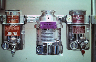
FIGURE 30-18 Three concentration-calibrated vaporizers mounted in series on the backbar of a now-obsolete anesthesia machine. In the absence of an interlock device, all three can be turned on simultaneously so that vapor from an upstream vaporizer can enter the vaporizing chambers of those downstream. On the two outer vaporizers, concentration is increased by turning the dial clockwise, whereas in the center vaporizer, the modern convention is followed in that concentration is increased by turning the dial counterclockwise.
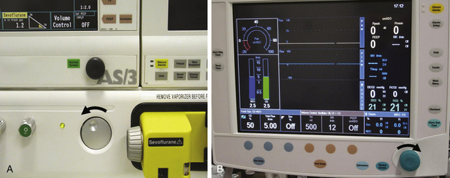
Confusion can also occur with certain models of GE Healthcare workstations equipped with the electronically controlled Aladin vaporizing system. In the Datex ADU workstation, agent concentration is increased by turning the concentration wheel counterclockwise, as is the convention for mechanical vaporizers. The Aisys Carestation also uses the Aladin vaporizing system, but in this workstation, the “com wheel” is turned clockwise to increase the agent concentration (Fig. 30-19, B). This can lead to setting errors, especially in institutions that have both Aisys and ADU workstations. It is therefore important that the anesthesiologist deliberately observe the dial and concentration mark settings when adjusting agent concentration.
Incorrect Filling of Vaporizers
Anesthetic agent overdosage or underdosage can occur if an agent-specific vaporizer is filled wholly or partially with an incorrect agent. If an empty concentration-calibrated vaporizer designed for one agent is filled with an agent for which it was not designed, the vaporizer concentration output may be erroneous.115,116 If a vaporizer designed for an agent with relatively low saturated vapor pressure (SVP) at room temperature (20° C; e.g., sevoflurane, 160 mm Hg; enflurane, 175 mm Hg) is filled with an agent that has a relatively high SVP (e.g., isoflurane, 239 mm Hg; halothane, 241 mm Hg), the output concentration will be greater than that set on the dial. The opposite occurs if a vaporizer designed for isoflurane or halothane is filled with sevoflurane or enflurane.
Theoretically, an extremely dangerous condition would arise if a vaporizer designed for methoxyflurane, an agent with an SVP of only 20.3 mm Hg at 20° C and an MAC of 0.16, were filled with halothane. A methoxyflurane vaporizer filled with halothane and set to deliver 1% methoxyflurane (6 MAC of methoxyflurane) would deliver 14.8% (approximately 20 MAC) halothane! Fortunately, methoxyflurane and its vaporizers are no longer available.
The outputs of erroneously filled vaporizers are shown in Chapter 3, Table 3-4. Erroneous filling affects the output concentration and consequently the MAC or potency output of the vaporizer.117 Thus a sevoflurane vaporizer set to 2% (1 MAC) but filled with isoflurane will deliver almost 3% (2.5 MAC) of isoflurane—that is, 2.5 times the anticipated anesthetic potency output (see Chapter 3, Table 3-4).
Erroneous filling of vaporizers may be prevented by careful attention to the specific agent and the vaporizer when filling is performed. Patented agent-specific fill devices, analogous to the quick-connect systems for medical gases, are available for all potent volatile anesthetic agents. Liquid anesthetic agents other than desflurane are packaged in bottles that have agent-specific collars. An agent-specific filling device has one end that fits the collar on the agent bottle and another end that fits only the vaporizer designed for that agent. Despite agent-specific fill devices, problems with erroneous fitting of a collar to the wrong bottle have been reported.117
Desflurane has a very high SVP at room temperature (669 mm Hg) and boils at 22.8° C. Erroneously filling a modern flow-splitting variable-bypass vaporizer, such as a Tec 7 or Vapor 2000, with desflurane could lead to very high concentration outputs of this agent. The theoretical consequences of erroneously filling a vaporizer with desflurane have been reported by Andrews and colleagues.118 They calculated that the most hazardous filling error would occur if an enflurane vaporizer were misfilled with desflurane. The calculated desflurane output of a misfilled enflurane vaporizer at a dial setting of 1% and a temperature of 22° C is 57.8%, or 9.6 MAC. For a misfilled isoflurane vaporizer at a dial setting equivalent to 1 MAC at 22° C, the calculated desflurane output is 10.2 MAC. A small increase in temperature would lead to a drastically increased output concentration, and the situation could become uncontrolled and potentially lethal if the temperature exceeded 22.8° C and desflurane were to boil.
Perhaps a more likely scenario is when an agent-specific vaporizer partially filled with a correct agent is topped off with an incorrect agent.117 This situation is more complex and less easily predicted in terms of vaporizer output, and significant errors can arise in delivered vapor administration. Halothane, enflurane, and isoflurane do not react chemically when mixed, but they do influence each other’s ease of vaporization. Halothane facilitates the vaporization of both enflurane and isoflurane and in the process is itself more likely to vaporize. The clinical consequences depend on the potencies of each of the mixed agents and on the delivered vapor concentrations. If a halothane vaporizer 25% full is refilled to 100% with isoflurane and set to deliver 1%, the halothane output is 0.41% (0.51 MAC), and the isoflurane output is 0.9% (0.78 MAC; see Chapter 3, Table 3-5).119 In this case, the output potency of 1.29 MAC is not far from the 1.25 MAC (1% halothane) expected.
On the other hand, an enflurane vaporizer 25% full and set to deliver 2% (1.19 MAC) enflurane topped off to 100% with halothane has an output of 2.43% (3.03 MAC) halothane and 0.96% (0.57 MAC) enflurane.117 This represents a total MAC of 3.6, or three times that intended. This illustrates why it is so important to avoid erroneous filling of vaporizers. If erroneous filling is suspected, the vaporizer should be emptied and, if necessary, serviced, flushed, and refilled with the correct agent.
Simultaneous Use of More Than One Vaporizer
Contemporary anesthesia vaporizers and their mounting systems incorporate an interlock system to prevent simultaneous use of more than one vaporizer and agent. Older anesthesia machine designs had up to three variable-bypass vaporizers arranged in series, such that fresh gas passed through each vaporizer, albeit through the bypass flow, to reach the common gas outlet of the anesthesia machine. Without an interlock device, which would have permitted only one vaporizer to be in use at any time, it was possible to have all three vaporizers on simultaneously (see Fig. 30-18). Apart from potentially delivering an anesthetic overdose to the patient, the agent from the upstream vaporizer could contaminate the agent or agents in the downstream vaporizers.120,121 During subsequent use, the output of the downstream vaporizer would be contaminated, and the concentration of the emerging gas and vapor mixture would be indeterminate—and it might even be lethal. With such in-series arrangements, care must be taken to ensure that only one vaporizer is on at any time; and to minimize risk in case cross-contamination should occur, the sequence of vaporizers from upstream to downstream should be such that the agent that has the lowest SVP is upstream; that is, it is farthest from the patient. The correct series sequence would therefore be 1) sevoflurane, 2) enflurane, 3) isoflurane, and 4) halothane, with halothane being closest to the common gas outlet of the anesthesia machine. The standard use of safety-interlock devices prevents the in-series arrangement and its potential consequences. Vaporizers are neither in series nor parallel because only one can be connected to the machine’s low-pressure system at any one time. The above discussion should therefore be of historical interest only (see Box 30-4, item D).
Although vaporizer interlock/exclusion systems are standard safety features on modern machines, failures of these systems have been reported. Failure may result in more than one vaporizer being on at the same time.122 Exclusion of the selected vaporizer has been described with a Select-a-tec system (GE Healthcare).122 It is therefore important that the anesthesiologist check the interlock system periodically for correct function.
The safety features of the vaporizer interlock system can also be defeated if a freestanding vaporizer is used in series with the FGF but downstream of the common gas outlet. Such arrangements, configured by the user, are potentially dangerous and should never be used.123
Pumping Effect
The now obsolete measured-flow vaporizers and some other, older designs of concentration-calibrated vaporizers were subject to the so-called pumping effect, which could result in increased output concentrations during mechanical ventilation when low FGF rates were in use. The explanation for this effect is that during positive-pressure ventilation, increased pressure in the vaporizer caused bypass gas to enter the vaporizing chamber, thereby increasing output. Contemporary vaporizing systems are designed to be compensated for or protected against the pumping effect. In certain models of Datex-Ohmeda anesthesia machines (GE Healthcare), vaporizer protection is afforded by an outlet check valve located just upstream of the common gas outlet; this configuration prevents increases in pressure in the patient circuit from being transmitted back into the machine and thence to the vaporizer.
Malignant Hyperthermia: Preparation for Susceptible Patients
If an anesthesia machine is to be used for a patient who is susceptible to malignant hyperthermia (MH), it has been recommended that the vaporizers be removed and that the machine be purged with oxygen before use. The Malignant Hyperthermia Association (MHA) has provided specific instructions on purging anesthesia machines of volatile agents to reduce the risk of exposure. However, these recommendations were developed from studies of older-generation machines. A major barrier to validating any guidelines for purging anesthesia machines is that a maximum “safe” concentration of potent inhaled volatile agent to which an MH-susceptible patient can be exposed is not known and likely never will be. In pigs an anesthetic concentration of 5 ppm is known not to trigger MH; therefore recent studies of purging anesthesia workstations have used this concentration as their endpoint. Modern anesthesia workstations are more complex and contain more gas-absorbing materials. A recent review of the literature concluded that current MHA guidelines124 for the United States were inadequate to prepare newer-generation workstations, which require more time for purging of anesthetic gases, autoclaving or replacement of parts, and modifications to the gas delivery system. A review of study recommendations for preparing an anesthesia machine for the MH-susceptible patient has been published.125 The authors proposed that new protocols be developed for each model of new workstation to prepare for an MH-susceptible patient.125 Current recommendations are summarized in Box 30-4 and Table 30-1.126-131
TABLE 30-1
Reported Purge Times Using an Oxygen Flow of 10 mL/min to Reach a 5 ppm Concentration of Anesthetic
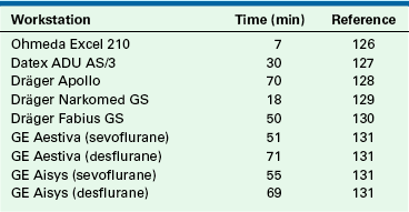
Use of Activated Charcoal Filters
As an alternative to purging the anesthesia workstation, Birgenheier and colleagues132 studied the efficacy of placing activated charcoal filters (Vapor-Clean; Dynasthetics, Salt Lake City) on both the inspiratory and expiratory sides of the circle system of several contaminated anesthesia machines and measured the time needed to flush the machine so that the delivered concentrations of isoflurane, sevoflurane, and desflurane would be less than 5 ppm. They also simulated a case in which MH is diagnosed 90 minutes after induction of anesthesia, and they measured how well activated charcoal filters limit further exposure. They found that the filters decreased the concentration of volatile anesthetic delivered by a contaminated machine to an acceptable level in less than 2 minutes, and the concentrations remained well below 5 ppm for at least 60 minutes. These authors concluded that activated charcoal filters provide an alternative approach to the 10 to 104 minutes of flushing time normally required to prepare a machine used previously to deliver a volatile anesthetic. Whether these filters should become standard of care is discussed in an editorial in the same journal issue.133
Possible Malfunctions
Anesthetic Agent Dosing Problems
Anesthetic agent underdosage may occur that results in light anesthesia, patient movement, or even awareness. Common causes include forgetting to turn the vaporizer on, especially after it has been turned off for refilling; an empty vaporizer; an incorrect concentration setting; or an incorrect agent in the vaporizer.
The unintentional delivery of high concentrations of anesthetic vapor may be caused by any kind of internal malfunction of the vaporizer. Therefore regular checking of function and output calibration are essential, and such checking should ideally be performed in the normal use environment of the vaporizer.
Although numerous design features have helped to make modern vaporizing systems safer for the patient, ideally, an agent-specific gas analyzer with user-adjustable high- and low-concentration alarm limits should be used in the patient circuit to monitor inhaled concentrations. A variety of such units using various technologies are available (see Chapter 8).
Incompatibility problems have been reported between Penlon Sigma Delta vaporizers and sevoflurane.134 One is a variable degree of corrosion of the plastic key-fill stoppers with resultant leakage of anaesthetic gas on both low- and high-pressure leak testing. Another problem relates to a yellow discoloration of the sevoflurane in the gauge chamber and partial disintegration of the indicator ball. It was found that different manufacturers of sevoflurane use formulations with different amounts of water content, varying between 357 ppm water in Ultane and 19 ppm in Minrad sevoflurane. Degradation and hydrogen fluoride production associated with the low-water sevoflurane formulations were accompanied by physical corrosion of the vaporizers, specifically etching of the sight glass and degradation of the metal filler port shoe, leading to possible leakage of sevoflurane.135 In September 2006 in the United Kingdom, Penlon recalled and replaced the affected vaporizers. Penlon altered the manufacturing process to use a polytetrafluoroethylene (PTFE) plastic–coated internal surface, but some older Penlon vaporizers may remain in circulation and may be subject to Lewis acid degradation.136-138
Desflurane Vaporizer Problems
The Tec 6 heated and pressurized desflurane vaporizer was introduced in 1993. Associated with the novel design, some new problems have been reported as the device has evolved. In particular there have been occasional reports of anesthetic agent overdosage because of a faulty control valve, which led to a recall of some Tec 6 vaporizers in 1994.139 A gas leak problem after the Tec 6 was turned off, associated with an inability to subsequently turn on the Tec 6 or other vaporizers mounted on the same machine, led to another change in design.140 There have been further sporadic reports of desflurane overdosage because of Tec 6 malfunctions, including one that led to cardiac arrest.141,142
Unusual yellow discoloration has been reported in the sight-glass display level of some D-Vapor desflurane vaporizers when filled for the first time with desflurane.143 An investigation by the manufacturer of desflurane (Suprane, Baxter Healthcare, Deerfield, IL) found that the discoloration resulted from oxidation of butylated hydroxytoluene (BHT), an antioxidant present in many polymers, including those in the closure mechanism of Suprane bottles (Saf-T-Fill), and that the vaporizer itself was not the cause.
The Aladin vaporizing system used on Datex-Ohmeda (GE Healthcare) workstations can also deliver desflurane. There is one report of this system, set to 5% with a 5 L/min gas flow, delivering 14% desflurane for about 2 minutes following decrease of the FGF to 0.70 L/min.144 The cause of the problem was thought to be that the one-way valve that prevents backflow of saturated vapor from the cassette via the inspiratory channel toward the bypass channel may have failed to close after lowering the FGF (see Chapter 3, Fig. 3-36). This problem may be more significant when desflurane is used, because the pressure in the desflurane Aladin cassette may exceed 1 atm due to its high vapor pressure when the temperature is greater than 22.8° C (boiling point of desflurane at 1 atm pressure).
Humidification Problems
Humidification of the inspired gases is desirable because it 1) prevents heat loss caused by evaporation of water from the tracheobronchial tree, 2) maintains moisture in the conducting airways and thereby facilitates ciliary function, and 3) prevents insensible water loss from the patient by evaporation. Humidity can be provided by heat and moisture exchange (HME) devices connected to the tracheal tube and by moistening of the inside of the breathing tubes and reservoir bag with water before use.145,146 In addition, unheated water vaporizers can be used to provide moisture to the patient. However, the disadvantage of any system that does not use heat is that it will cool as evaporation takes place, and the amount of humidity generated will therefore be reduced.
Heated humidifiers (vaporizers) are devices through which the inspired gases are passed in order to saturate the gases with water at the temperature of the humidifier. The dry gases either bubble through the humidifier or pass over the surface of the water. The heat is usually provided by electricity.
The advantage of this type of system is that the inspired gases become saturated with water at an increased temperature. However, as the gas cools upon leaving the humidifier, condensation occurs in the tubing, and the amount of humidity delivered to the patient decreases. The condensation problem can be managed by heating the gases in the inspiratory hose either externally or internally with a heating wire. Keeping the distance from the humidifier to the patient as short as possible also decreases the amount of condensation (see also Chapter 7).
Another technique is to heat the humidifier to a temperature above body temperature, so that as the inspired gases cool in the inspiratory tubing, they enter the tracheal tube at the desired temperature. This technique must be used carefully to avoid burning the patient’s tracheobronchial tree. It is therefore mandatory to monitor the temperature of the inspired gases at the tracheal tube to ensure that the gases are not too hot. Because gases delivered to the patient have at most 100% relative humidity, there is little chance that the patient will experience fluid overload when a heated humidifier is used. Another problem with this technique is that water will condense (“rain out”) into the tubing as the gases cool. A significant amount of water can collect in the tubing, which can cause increased resistance to breathing or be accidentally delivered to the patient.
Hazards associated with the HME, or “artificial nose,” include misconnection, obstruction, and disconnection.147,148 A heated humidifier may cause bulk water delivery to the patient, thermal trauma to the airway, or obstruction of the breathing circuit, or it may become an electrical or fire hazard. These devices are electrically powered, and thermostat failure may lead to superheating of the gases in the humidifier, causing the plastic inspiratory tubing to soften.149 A soft inspiratory hose may become completely occluded or may develop a hole, resulting in a large leak and thereby preventing ventilation of the patient. This problem can be avoided by making sure that the gas flow through the humidifier is initiated before the humidifier is turned on.150
Although fire in the OR is an uncommon event, a 2010 report of two fires in one brand of heated humidified circuit drew further attention to this potential danger. The authors considered that the inherent dangers of such a circuit did not warrant their continued use.151
Humidity can also be provided with a nebulizer technique. Nebulizers create droplets of water either by a jet of gas over the surface of the water or ultrasonically. Unlike the heated vaporizer, the nebulizer creates three hazards: 1) it can act as a nidus for bacterial transmission, 2) respiratory resistance may increase, and 3) the patient can become overhydrated. Therefore extreme care should be taken in cleaning the nebulizer; sterile water must be used, and the amount of water delivered must be carefully monitored. In addition, because of the risk of increased respiratory resistance, nebulizers should probably not be used with patients who are breathing spontaneously.
When using heated humidifiers or nebulizers, the anesthesiologist should guard against 1) fluid overload, 2) thermal injury, 3) additional sites for disconnection within the breathing circuit, 4) obstruction of gas flow, 5) burning of the equipment because of electrical malfunction, 6) shock hazards, and 7) the risk of infection transmission via the nebulizer.
Electrical Failure
Contemporary anesthesia workstations rely on electrical and mechanical devices to function. The power cord of the machine uses 90 to 130 V at 50 to 60 Hz alternating current (AC). On the workstation itself are usually at least four convenience receptacles that can provide electrical power for such additional equipment as monitors, anesthesia information management systems (AIMS), and infusion pumps that do not draw large amounts of current. There is also a rechargeable battery that acts as a back-up power source in case the external power fails.
The preoperative check of a workstation includes a status review of the AC power and the reserve battery (Fig. 30-20). A discharged battery may require up to 16 hours to recharge, so cases should not be started if either of these is not functioning. The ON/OFF switch on a traditional machine mechanically activates the flow of gases through the flowmeters and turns on the electrical power. In the event of an electrical power failure, having the switch turned on allows gases to flow to the flowmeters. The battery provides power to the electrical devices built into the machine; these include the ventilator, the alarm system, and the integral monitors. External electrical appliances plugged into the convenience receptacles are not powered by the battery.
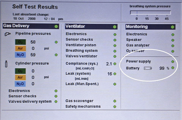
Usually the back-up battery provides power for approximately 40 minutes. When its voltage drops to below about 10 V, all power to the machine ceases in order to prevent a deep discharge of the battery. Failure of the battery would cause the monitors, alarm system, and ventilator on the machine to stop functioning. Manual ventilation would then be required.
In some institutions the anesthesia workstation and AIMS are connected to an uninterruptible power supply (UPS; Fig. 30-21), which extends the amount of time the workstation can function in the event direct current (DC) power is lost. The workstation and/or UPS should be connected to a wall outlet that would be energized by the institution’s emergency generator power supply in the event power is lost from the electric utility company.
Leaving the machine power on with the electrical cord disconnected from the wall is a common cause of battery discharge. This should be discovered on the preuse check of the equipment, and ideally the machine should not be used until the battery has been recharged. Another source of trouble is accidentally plugging the power cord from the machine into one of the machine convenience receptacles; in essence, the machine is plugged into itself and has no external power supply. The anesthesiologist is alerted to this problem if the AC power failure indicator is activated and the “battery in use” warning light is on.
The electrical portion of the machine has several circuit breakers, which generally protect circuits for the AC power supply, the battery, and the convenience receptacles. When any of the electrical systems of the machine malfunction, the circuit breakers should be checked to determine whether they have been tripped. The anesthesiologist is sometimes responsible for anesthesia machine electrical failure. In one reported case, the anesthesiologist had intended to turn off the ventilator but instead turned off the main power switch to the machine. The effect was to turn off the gas flow, the alarm system, and the ventilator. In this situation, because the alarm system no longer functioned, it was up to the anesthesiologist, through vigilance, to recognize that the machine had been turned off and to intervene appropriately.152
With contemporary anesthesia workstations being dependent on electrical power, it is important to plan for such failures to ensure patient safety. Recent reports and an editorial have highlighted this topic and have proposed a preparedness checklist.153-155 Total electrical failure in the OR affects all equipment that does not have a battery back-up system. This includes all monitors, the anesthesia machine, the cardiopulmonary bypass machine, and the electric lights. All institutions should have an emergency plan for this type of utility failure. A sentinel alert from The Joint Commission requires that each health care facility must assess the risk of electrical power failure, at various degrees of magnitude and impact severity, and make plans to deal with such an emergency.156 For more information, see Chapter 31.
Electromagnetic interference (EMI) is another potential cause of delivery system failure and has been reported to cause ventilator failure.157 The design of contemporary electronic equipment makes EMI less likely, and all equipment is tested for EMI. Modern cellular telephones do not appear to interfere with OR equipment.
Hazards from Interactions with Carbon Dioxide Absorbent
Since 1990, there have been several reports of patients who developed increased levels of carboxyhemoglobin in response to accumulation of carbon monoxide in the circle system, generated when desflurane, enflurane, and to a lesser extent isoflurane interact with dry (desiccated) carbon dioxide absorbent, particularly Baralyme (no longer being manufactured).158 Although no case of patient harm has been reported to date, carbon monixide represents a potential hazard of which the anesthesia caregiver should be aware.159 Measures to decrease this potential hazard include using absorbent that has the standard complement of water or addition of liquid water to the top of the absorbent. Fresh gas should be turned off at the end of each case to prevent desiccation of the absorbent, and consideration should be given to replacing the absorbent more frequently, especially if the machine has been left unused for some time, such as over a weekend.
Another approach is to use a carbon dioxide absorbent that does not contain strong bases, such as barium hydroxide (BaOH2) and potassium hydroxide (KOH).160,161 For example, Amsorb (Armstrong Medical, Coleraine, Northern Ireland) is a carbon dioxide absorbent that does not contain a strong base and does not form carbon moxide or compound A in vitro. It also turns purple when desiccated, which is an additional advantage.
Desiccated Baralyme acting on sevoflurane can produce absorber temperatures that exceed 300° C, and it can lead to both fires and explosions.162-165 Animal studies and a bench model demonstrate fires and explosions with sevoflurane, and there are now several reports of fires and explosions in clinical practice with sevoflurane, but none with desflurane or isoflurane. In one case, a patient was injured. In late 2004, the manufacturer of Baralyme discontinued its distribution, which should minimize or even eliminate the problems of fire and explosion. The risk of fire and explosion is considered to be much less with soda lime, although it has been suggested that the absorber temperature be routinely monitored using a skin probe.166
Prevention of Complications
Complications from the anesthesia delivery system are uncommon, but when they do occur, they are usually due to user error rather than actual equipment failure.167 Contemporary anesthesia workstations incorporate many safety design features, and older systems that are obsolete should no longer be used. Criteria for determining obsolescence of an anesthesia machine have been published by the ASA (Box 30-5). User education/in-servicing is essential if sophisticated equipment, such as a computerized anesthesia workstation, is to be used appropriately.168 Education of medical as well as ancillary (nursing/technical) staff is also important, because they may unwittingly contribute to the occurrence of a complication.169,170
Excellent written and interactive electronic materials are available from some manufacturers of anesthesia workstations and serve to supplement the personal in-servicing of users and operators of new equipment.171,172
Preuse Checkout of the Delivery System
The purpose of the preanesthetic checkout is to determine that all the necessary equipment is present and functioning as expected before the induction of anesthesia. The importance of this is self-evident; moreover, its usefulness is supported in the anesthesia literature, which describes anesthesia machine malfunctions that could have been discovered before the case began had a thorough check of the equipment been performed.173
When the delivery system is checked before the start of anesthesia, it should be set up in the way it will be used during the case. Moving the machine after the case has begun, modifying the breathing circuit with a humidifier, or adding other components can affect the performance of the anesthesia delivery system. Inspecting the machine in the condition in which it will be used during the operation minimizes this type of problem. However, the preoperative equipment check does not guard against the problem of intraoperative equipment failure, so the anesthesiologist must be vigilant in the monitoring of equipment performance and must be ready to intervene in any hazardous situation.
Studies have shown that anesthesia providers often fail to properly perform the preuse checkout of their anesthesia delivery system174 and that instructional review improves residents’ performance of the checkout.175 This may be due to the complexity of previously published checkouts.176 The preuse checking of anesthesia equipment has been associated with a decreased risk of severe postoperative morbidity and mortality.177
As the anesthesia workstation evolved since publication of the FDA 1993 checkout recommendations, it became clear that a single checkout recommendation could not apply to all delivery systems. In 2004, a subcommittee of the ASA Committee on Equipment and Facilities was formed to develop a guideline that described what items should be checked rather than describing the methodology of checking. Seven requirements were identified as the underlying rationale for the guideline:
1. Reliable delivery of oxygen at any appropriate concentration up to 100%
2. Reliable means of positive-pressure ventilation
3. Back-up ventilation equipment available and functioning
4. Controlled release of positive pressure in the breathing circuit
5. Anesthesia vapor delivery (if intended as part of the anesthetic plan)
The new checkout guidelines were approved by the ASA in 2007 and were published in 2008 (see Chapter 32, Table 32-2).178 (For a more detailed description of the checkout guidelines, see Chapter 32.179) Suggested preuse checkouts for a number of contemporary workstations are also available at the ASA web site (www.asahq.org).
The ASA guidelines indicate which items could be checked by a technician alone and which must be checked in conjunction with the anesthesia provider. Notwithstanding the role of the technician, the guidelines emphasize, however, that the ultimate responsibility for ensuring that equipment functions properly lies with the anesthesia provider.
The new electronic workstations have preuse checkouts in which many of the checks are automated, but some must be completed by the user. It is essential that the user understand how to perform the required tasks. For example, the user must correctly assemble and connect the breathing system to the workstation. The automated checkout is then able to pressurize the system to measure compliance and check for leaks but not necessarily to check for correct gas flow through the components. It may be possible for a breathing system to be incorrectly assembled, be gas tight, yet not permit any gas to flow to the patient.
Some anesthesia workstations (Dräger Narkomed 6400, Apollo, and Fabius GS; Datascope [now Mindray Medical, Mahwah, NJ] Anestar) use fresh gas decoupling (FGD) to ensure that changes in FGF do not affect the desired (dialed-in) tidal volume delivered to the patient’s airway. During the inspiratory phase of IPPV, only gas from the piston chamber (Dräger) or bellows (Anestar) is delivered to the inspiratory limb of the circle system, because the decoupling valve closes to divert FGF into the reservoir bag. FGD circuits differ from the traditional circle system in design and therefore may be associated with different problems, including detection of an air leak into the breathing system during the exhalation phase of positive-pressure ventilation180 and failure of the FGD valve, resulting in failure to ventilate in the ventilator (but not in manual/bag mode; see Fig. 30-22).181 All indicated and required monitors must be available and used correctly with alarm limits and alarm volumes set appropriately for the individual patient’s situation. Anesthesia equipment should be regularly serviced by authorized personnel, and the equipment should be updated as necessary to conform to any existing requirements. A 2004 statement concerning guidelines to determine anesthesia machine obsolescence has been published by the ASA.182
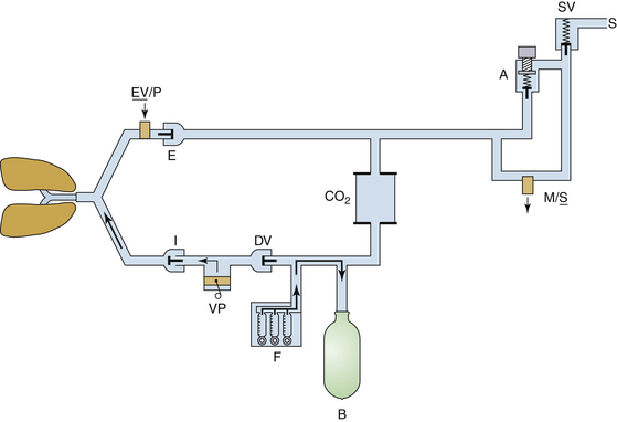
FIGURE 30-22 Fresh gas decoupling breathing system as used in a Fabius GS workstation (Dräger Medical, Telford, PA). The fresh gas decoupling valve (DV) is located between the ventilator piston (VP) and the fresh gas inflow (F). During positive-pressure inspiration, anesthesia gas in the ventilator chamber is driven into the breathing circuit by the ventilator piston. The positive pressure causes the DV to close, directing fresh gas inflow into the reservoir bag (B). If the decoupling valve fails to close, gas inflow from the ventilator takes the path of least resistance into the reservoir bag, rather than past the inspiratory unidirectional valve (I), to ventilate the patient’s lungs. Ventilation of the lungs is possible in bag mode. EV/P, expiratory valve/positive end-expiratory pressure valve; A, adjustable pressure limit (APL) valve; M/S, APL bypass valve; SV, scavenging valve; S, scavenging system. (Courtesy Michael A. Olympio, MD.)
A preuse checkout of the delivery system should be developed by each institution to suit local needs. Item 1 on any preuse checkout should be that a back-up means of ventilation should be made immediately available, and its function should be verified. Testing the function of the self-inflating resuscitation bag during the preuse checkout is essential. Occasionally, a bag is found to be faulty; either it does not generate positive pressure when it is squeezed, or it does not release positive pressure when it is longer being squeezed. Thus in the event of a delivery system failure, the patient’s lungs can be ventilated with room air (or oxygen if a tank is available) using a self-inflating resuscitation bag.183
Recent studies suggest that awareness is increasing regarding the importance of the preuse checkout and management of machine-related critical incidents.184-187 Simulation of anesthesia equipment failure has been used to assess residents’ performance in the management of these scenarios.188 At least one national anesthesiology board has even incorporated aspects of the preuse checkout into the objective structured clinical evaluation component of its board examination in anesthesiology.189
The anesthesia delivery system may cause complications to the patient because of misuse or component failure. Anesthesia equipment failure and misuse represent a small proportion of anesthesia-related malpractice claims, but when they occur, the severity of injury is great. Use error is more common than pure equipment failure. The delivery system continues to evolve as more is learned about patient safety and as design and monitoring features are added. Clearly, a basic understanding of the structure and function of the delivery system will enhance patient safety by avoiding misuse and facilitating troubleshooting or alternative techniques if a component fails.
References
1. Flanagan J.C. The critical incident technique. Psychol Bull. 1954;51:327–358.
2. Cooper J.B., et al. Preventable anesthesia mishaps. Anesthesiology. 1978;49:399–406.
3. Cooper J.B., et al. An analysis of major errors and equipment failures in anesthesia management. Anesthesiology. 1984;60:34–42.
4. Sykes M.K. Incidence of mortality and morbidity due to anaesthetic equipment failure. Eur J Anaesthesiol. 1987;4:198–199.
5. Buffington C.W., Ramanathan S., Turndorf H. Detection of anesthesia machine faults. Anesth Analg. 1984;63:79–82.
6. Anesthesia apparatus checkout recommendations. Rockville, MD: U.S. Food and Drug Administration; 1986.
7. March M.G., Crowley J.J. An evaluation of anesthesiologists’ present checkout methods and the validity of the FDA checklist. Anesthesiology. 1991;75:724–729.
8. Kumar V., Hintze M.S., Jacob A.M. A random survey of anesthesia machines and ancillary monitors in 45 hospitals. Anesth Analg. 1988;67:644–649.
9. Webb R.K., Currie M., Morgan C.A., et al. The Australian Incident Monitoring Study: an analysis of 2000 incident reports. Anaesth Intensive Care. 1993;21:520–528.
10. Webb R.K., Russell W.J., Klepper I., Runciman W.B. The Australian Incident Monitoring Study. Equipment failure: an analysis of 2000 incident reports. Anaesth Intensive Care. 1993;21:673–677.
11. Russell W.J., Webb R.K., Van de Walt J.H., Runciman W.B. The Australian Incident Monitoring Study. Problems with ventilation: an analysis of 2000 incident reports. Anaesth Intensive Care. 1993;1:617–620.
12. Eichhorn J.H. Prevention of intraoperative anesthesia accidents and related severe injury through safety monitoring. Anesthesiology. 70, 1989. 572–527
13. Caplan R.A., Vistica M.F., Posner K.L., Cheney F.W. Adverse anesthetic outcomes arising from gas delivery equipment: a closed claims analysis. Anesthesiology. 1997;87:741–748.
14. Posner Karen L. ASA Closed Claims Project. Personal communication. May 2012.
15. American Society for Testing and Materials (ASTM): Standard specification for particular requirements for anesthesia workstations and their components (ASTM F1850-00). West Conshohocken, PA, 2005, ASTM.
16. ASTM. Specification for minimum performance and safety requirements for components and systems of anesthesia gas machines (ASTM F1161-88). Philadelphia: ASTM; 1989.
17. American Society of Anesthesiologists (ASA): Standards for basic anesthetic monitoring. Approved by the ASA House of Delegates on October 21, 1986; last amended on October 20, 2010, with an effective date of July 1, 2011. Park Ridge, IL, ASA.
18. Schreiber P. Safety guidelines for anesthesia systems. Telford, PA: North American Dräger; 1985.
19. Abraham Z.A., Basagoitia J. A potentially lethal anesthesia machine failure. Anesthesiology. 1987;66:589–590. (letter)
20. Feeley T.W., Hedley-Whyte J. Bulk oxygen and nitrous oxide delivery systems: design and dangers. Anesthesiology. 1976;44:301–305.
21. O’Connor C.J., Hobin K.F. Bypassing the diameter-indexed safety system. Anesthesiology. 1989;71:318–319.
22. Anderson B., Chamley D. Wall outlet oxygen failure. Anaesth Intensive Care. 1987;15:468–469. (letter)
23. Mudumbai S.C., Fanning R., Howard S.K., Davies M.F., Gaba D.M. Use of medical simulation to explore equipment failures and human-machine interactions in anesthesia machine pipeline supply crossover. Anesth Analg. 2010;110:1292–1296.
24. Surgery mix-up causes 2 deaths. New Haven Register. January 20, 2002.
25. Jawan B., Lee J.H. Cardiac arrest caused by an incorrectly filled oxygen cylinder: a case report. Br J Anaesth. 1990;64:749–751.
26. Holland R. Wrong gas disaster in Hong Kong. APSF Newslett. 1989;4:26.
27. Lorraway P.G., Savoldelli G.L., Joo H.S., et al. Management of simulated oxygen supply failure: is there a gap in the curriculum? Anesth Analg. 2006;102:865–867.
28. Bonsu A.K., Stead A.L. Accidental cross-connexion of oxygen and nitrous oxide in an anaesthetic machine. Anaesthesia. 1983;38:767–769.
29. Lacoumenta S., Hall G.M. A burst oxygen pipeline. Anaesthesia. 1983;38:596–597. (letter)
30. Carley R.H., Houghton I.T., Park G.R. A near disaster from piped gases. Anaesthesia. 1984;39:891–893.
31. Bancroft M.L., du Moulin G.C., Hedley-White J. Hazards of hospital bulk oxygen delivery systems. Anesthesiology. 1980;52:504–510.
32. Schumacher S.D., Brockwell R.C., Andrews J.J., Ogles D. Bulk liquid oxygen supply failure. Anesthesiology. 2004;100:186–189.
33. Feeley T.W., Hedley-Whyte J. Bulk oxygen and nitrous oxide delivery systems: design and dangers. Anesthesiology. 1976;44:301–305.
34. Beudoin M.G. Oxygen needle valve obstruction. Anaesth Intensive Care. 1988;16:130–131. (letter)
35. Khalil S.N., Neuman J. Failure of an oxygen flow control valve. Anesthesiology. 1990;73:355–356.
36. Williams A.R., Hilton P.J. Selective oxygen leak: a potential cause of patient hypoxia. Anaesthesia. 1986;41:1133–1134.
37. Hanning C.D., Kruchek D., Chunara A. Preferential oxygen leak: an unusual case. Anaesthesia. 1987;42:1329–1330. (letter)
38. Moore J.K., Railton R. Hypoxia caused by a leaking rotameter: the value of an oxygen analyser. Anaesthesia. 1984;39:380–381. (letter)
39. Cole A.G., Thompson J.B., Fodor I.M., et al. Anaesthetic machine hazard from the Selectatec block. Anaesthesia. 1983;38:175–177. (letter)
40. ASA. Guidelines for determining anesthesia machine obsolescence. Park Ridge, IL: ASA Committee on Equipment and Facilities; June 2004.
41. Richards C. Failure of a nitrous oxide–oxygen proportioning system. Anesthesiology. 1989;71:997–999.
42. Goodyear C.M. Failure of nitrous oxide-oxygen proportioning device. Anesthesiology. 1990;72:397–398.
43. Ghanooni S., Wilks D.H., Finestone S.C. A case report of an unusual disconnection. Anesth Analg. 1983;62:696–697.
44. Henshaw J. Circle system disconnection. Anaesth Intensive Care. 1988;16:240. (letter)
45. Horan B.F. Unusual disconnection. Anaesth Intensive Care. 1987;15:466–467. (letter)
46. Ripp C.H., Chapin J.W. A bellows leak in an Ohio anesthesia ventilator. Anesth Analg. 1985;64:942. (letter)
47. Ripp C.H., Chapin J.W. A bellows leak in an Ohio anesthesia ventilator. Anesth Analg. 1985;64:942. (letter)
48. Spoor J. Ventilator malfunction. Anaesth Intensive Care. 1986;14:329. (letter)
49. Pashayan A.G., Gravenstein J.S., Cassisi N.J., McLaughlin G. The helium protocol for laryngotracheal operations with CO2 laser: a retrospective review of 523 cases. Anesthesiology. 1988;68:801–804.
50. Mathes D.D. Bleomycin and hyperoxia exposure in the operating room. Anesth Analg. 1995;81:624–629.
51. ASA Task Force on Operating Room Fires. Practice advisory for the prevention and management of operating room fires. Anesthesiology. 2008;108:786–801.
52. ECRI Institute. New clinical guide to surgical fire prevention. Health Devices. 38(10), 2009.
53. Wan Y.L., Swan M. Exotic obstruction. Anaesth Intensive Care. 1990;18:274. (letter)
54. Boscoe M.J., Baxter R.C. Failure of anaesthetic gas supply. Anaesthesia. 1983;38:997–998. (letter)
55. Hogan T.S. Selectatec switch malfunction. Anaesthesia. 1985;40:66–69.
56. Milliken R.A., Bizzarri D.V. An unusual cause of failure of anesthetic gas delivery to a patient circuit [letter]. Anesth Analg. 1984;63:1047–1048.
57. Eisenkraft J.B., Sommer R.M. Flapper valve malfunction. Anesth Analg. 1988;67:1132. (letter)
58. Sommer R.M., Bhalla G.S., Jackson J.M., et al. Hypoventilation caused by ventilator valve rupture. Anesth Analg. 1988;67:999–1001.
59. Lamarche Y. Anaesthetic breathing circuit leak from cracked oxygen analyzer sensor connector [letter]. Can Anaesth Soc J. 1985;32:682–683.
60. Gravenstein D., Wilkhu H., Liem E.B., Tilman S., Lampotang S. Aestiva ventilation mode selector switch failures. Anesth Analg. 2007;104:860–862.
61. Mushlin P.S., Mark J.B., Elliott W.R., et al. Inadvertent development of subatmospheric airway pressure during cardiopulmonary bypass. Anesthesiology. 1989;71:459–462.
62. Ghani G.A. Fresh gas flow affects minute volume during mechanical ventilation. Anesth Analg. 1984;63:619.
63. Scheller M.S., Jones B.R., Benumof J.L. The influence of fresh gas flow and I:E ratio on tidal volume and PaCO2 in ventilated patients. J Cardiothoracic Anesth. 1989;3:564–567.
64. Birch A.A., Fisher N.A. Leak of soda lime seal after anesthesia machine check [letter]. J Clin Anesth. 1989;1:474–476.
65. Andrews J.J., Johnston R.V., Bee D.E., et al. Photodeactivation of ethyl violet: a potential hazard of sodasorb. Anesthesiology. 1990;72:59–64.
66. Nunn J.F. Carbon dioxide cylinders on anaesthetic apparatus. Br J Anaesth. 1990;65:155–156.
67. Razis P.A. Carbon dioxide: a survey of its use in anaesthesia in the U.K. Anaesthesia. 1989;44:348–351.
68. Todd D.B. Dangers of CO2 cylinders on anesthetic machines. Anaesthesia. 1995;50:911–912.
69. Ellett A.E., Shields J.C., Ifune C., Roa N., Vannucci A. A near miss: a N2O-CO2 mix-up despite current safety standards. Anesthesiology. 2009;110:1429.
70. Eger E.I., 2nd. Anesthetic systems: construction and function. In: Eger E.I., ed. Anesthetic uptake and action. Baltimore: Williams & Wilkins; 1974:206–227.
71. Conway C.M. Anaesthesia breathing systems. In: Scurr C.F., Feldman S., eds. Scientific foundations of anaesthesia. London: Heinemann; 1982:557–566.
72. Forrest P.R. Defective anaesthetic breathing circuit. Can J Anaesth. 1987;34:541–542. (letter)
73. Jackson F.J. Tests for co-axial systems [letter]. Anaesthesia. 1988;43:1060–1061.
74. Hewitt A.J., Campbell W. Unusual damage to a Bain system [letter]. Anaesthesia. 1986;41:882–883. (letter)
75. Goldman J.M., Phelps R.W. No flow anesthesia [letter]. Anesth Analg. 1987;66:1339.
76. Koga Y., Iwatsuki N., Takahashi M., et al. A hazardous defect in a humidifier. Anesth Analg. 1990;71:712.
77. Schroff P.K., Skerman J.H. Humidifier malfunction: a cause of anesthesia circuit occlusion. Anesth Analg. 1988;67:710–711.
78. Spurring P.W., Small L.F. Breathing system disconnexions and misconnexions: a review of some common causes and some suggestions for improved safety. Anaesthesia. 1983;38:683–688.
79. Olympio M.A., Stoner J. Tight mask fit could have prevented “airway” obstruction. Anesthesiology. 1992;77:822–825.
80. Peady C.J. Another report of obstruction of a heat and moisture exchange filter. Can J Anesth. 2002;49:1001.
81. Arellano R., Ross D., Lee K. Inappropriate attachment of PEEP valve causing total obstruction of ventilation bag. Anesth Analg. 1987;67:1050–1051.
82. ECRI Institute. PEEP valves in anesthesia circuits. Health Devices. 1983;13:24.
83. Anagnostou J.M., Hults S., Moorthy S.S. PEEP valve barotrauma. Anesth Analg. 1990;70:674–675.
84. Goldman J.M., Phelps R.W. No flow anesthesia [letter]. Anesth Analg. 1987;66:1339.
85. Sharrock N.E., Leith D.E. Potential pulmonary barotrauma when venting anesthetic gases to suction. Anesthesiology. 1977;46:152–154.
86. Adams A.P. Breathing system disconnections. Br J Anaesth. 1994;73:46–54.
87. Sara C.A., Wark H.J. Disconnection: an appraisal. Anaesth Intensive Care. 1986;14:448–452.
88. Raphael D.T., Weller R.S., Doran D.J. A response algorithm for the low-pressure alarm condition. Anesth Analg. 1988;67:876–883.
89. Slee T.A., Pavlin E.G. Failure of a low-pressure alarm associated with use of a humidifier. Anesthesiology. 1988;69:791–793.
90. Ghanooni S., Wilks D.H., Finestone S.C. A case report of an unusual disconnection. Anesth Analg. 1983;62:696–697.
91. Eisenkraft J.B. Potential for barotrauma or hypoventilation with the Dräger AV-E ventilator. J Clin Anesth. 1989;1:452–456.
92. Kibelbek M.J. Cable trapped under Dräger Fabius automatic pressure limiting valve causes inability to ventilate. Anesthesiology. 2007;106:639–640.
93. Hennefent S., Suslowicz B. Circuit leak from capnograph sampling line lodged under APL valve. Anesth Analg. 2010;111:578.
94. Robards C., Corda D. A potential hazard involving the gas sampling line and the adjustable pressure limiting valve on the Dräger Apollo anesthesia workstation. Anesth Analg. 2010;111:579.
95. Vijayakumar A., Saxena D.K., Pillay A.S., Darsow R. Massive leak during manual ventilation: adjustable pressure limiting valve malfunction not detected by pre-anesthetic checkout. Anesth Analg. 2010;111:579–580.
96. Choi J.J., Guida J., Wu W.H. Hypoventilatory hazard of an anesthetic scavenging device. Anesthesiology. 1986;65:126–127.
97. Lanier W.L. Intraoperative air entrainment with Ohio Modulus anesthesia machine. Anesthesiology. 1986;64:266–268.
98. Sandberg W.S., Kaiser S. Novel breathing system architecture: new consequences of old problems. Anesthesiology. 2004;100:755–756.
99. Baraka A., Muallem M. Awareness during anaesthesia due to a ventilator malfunction. Anaesthesia. 1979;34:678–679.
100. Waterman P.M., Pautler S., Smith R.B. Accidental ventilator-induced hyperventilation. Anesthesiology. 1978;48:141.
101. Longmuir J., Craig D.B. Inadvertent increase in inspired oxygen concentration due to defect in ventilator bellows. Can Anaesth Soc J. 1976;23:327–329.
102. Dean H.N., Parsons D.E., Raphaely R.C. Bilateral tension pneumothorax from mechanical failure of anesthesia machine due to misplaced expiratory valve. Anesth Analg. 1971;50:195–198.
103. Sears B.E., Bocar N.D. Pneumothorax resulting from a closed anesthesia ventilator port. Anesthesiology. 1977;47:311–313.
104. Sprung J., Samaan F., Hensler T., et al. Excessive airway pressure due to ventilator control valve malfunction during anesthesia for open heart surgery. Anesthesiology. 1990;73:1035–1038.
105. Sprung J., Samaan F., Hensler T., Atlee J.L., 3rd., Kampine J.P. Excessive airway pressure due to ventilator control valve malfunction during anesthesia for open heart surgery. Anesthesiology. 1990;73:1035–1038.
106. Roth S., Tweedie E., Sommer R.M. Excessive airway pressure due to a malfunctioning anesthesia ventilator. Anesthesiology. 1986;65:532–534.
107. Henzig D. Insidious PEEP from a defective ventilator gas evacuation outlet valve. Anesthesiology. 1982;57:251–252.
108. Pressure limit control, operator’s instruction manual. Telford, PA: North American Dräger; 1988.
109. Ohmeda 7000 electronic anesthesia ventilator, service manual. Madison, WI: Ohmeda, The BOC Group; 1985.
110. Kopriva C.J., Lowenstein E. An anesthetic accident: cardiovascular collapse from liquid halothane delivery. Anesthesiology. 1969;30:246.
111. Dräger Vapor 19.n operating instructions. Lübeck, Germany, 1998, Drägerwerk AG.
112. Ohmeda Tec 5 continuous flow vaporizer: operation and maintenance manual. Madison, WI: Ohmeda; 1989.
113. Sinclair A., van Bergen J. Vaporizer overfilling. Can J Anesth. 1993;40:77–78.
114. Hardy J.F. Vaporizer overfilling. Can J Anesth. 1993;40:1–3.
115. Bruce D.L., Linde H.W. Vaporization of mixed anesthetic liquids. Anesthesiology. 1984;60:342–346.
116. Chilcoat R.T. Hazards of mis-filled vaporizers: summary tables. Anesthesiology. 1985;63:726–727.
117. Riegle E.V., Desertspring D. Failure of the agent-specific filling device. Anesthesiology. 1990;73:353–354.
118. Andrews J.J., Johnston R.V., Jr., Kramer G.C. Consequences of misfiling contemporary vaporizers with desflurane. Can J Anaesth. 1993;40:71–76.
119. Korman B., Ritchie I.M. Chemistry of halothane-enflurane mixtures applied to anesthesia. Anesthesiology. 1985;63:152–156.
120. Dorsch S.E., Dorsch J.A. Chemical cross-contamination between vaporizers in series. Anesth Analg. 1973;52:176–180.
121. Silvasi D.L., Haynes A., Brown A.C.D. Potentially lethal failure of the vapor exclusion system. Anesthesiology. 1990;71:289–291.
122. Cudmore J., Keogh J. Another Selectatec switch malfunction. Anaesthesia. 1990;45:754–756.
123. Marks W.E., Bullard J.R. Another hazard of freestanding vaporizers: increased anesthetic concentration with reversed flow of vaporizing gas. Anesthesiology. 1976;45:445.
124. Beebe J.J., Sessler D.I. Preparation of anesthesia machines for patients susceptible to malignant hyperthermia. Anesthesiology. 1988;69:395–400.
125. Kim T.W., Nemergut M.E. Preparation of modern anesthesia workstations for malignant hyperthermia-susceptible patients: a review of past and present practice. Anesthesiology. 2011;114:205–212.
126. Prinzhausen H., Crawford M.W., O’Rourke J., Petroz G.C. Preparation of the Drager Primus anesthetic machine for malignant hyperthermia-susceptible patients. Can J Anaesth. 2006;53:885–890.
127. Schonell L.H., Sims C., Bulsara M. Preparing a new generation anaesthetic machine for patients susceptible to malignant hyperthermia. Anaesth Intensive Care. 2003;31:58–62.
128. Crawford M.W., Prinzhausen H., Petroz G.C. Accelerating the washout of inhalational anesthetics from the Drager Primus anesthetic workstation: Effect of exchangeable internal components. Anesthesiology. 2007;106:289–294.
129. Gunter J.B., Ball J., Than-Win S. Preparation of the Drager Fabius anesthesia machine for the malignant hyperthermia susceptible patient. Anesth Analg. 2008;107:1936–1945.
130. Whitty R.J., Wong G.K., Petroz G.C., et al. Preparation of the Drager Fabius GS workstation for malignant hyperthermia-susceptible patients. Can J Anaesth. 2009;56:497–501.
131. Jones C., Bennett K., Kim T.W., et al. Preparation of Datex-Ohmeda Aestiva and Aisys anaesthetic machines for use in malignant hyperthermia-susceptible patients. Anaesth Intensive Care. 2012;40:490–497.
132. Birgenheier N., Stoker R., Westenskow D., Orr J. Activated charcoal effectively removes inhaled anesthetics from modern anesthesia machines. Anesth Analg. 2011;112:1363–1370.
133. Block F.E., Jr. Malignant hyperthermia and charcoal absorbent: too hot to handle. Anesth Analg. 2011;112:1270–1271.
134. O’Neill B., Hafiz M.A., De Beer D.A. Corrosion of Penlon sevoflurane vaporizers. Anaesthesia. 2007;62:421.
135. Saltarelli M. Abbott addresses sevoflurane formulation. APSF Newslett. 22(4), 2008.
136. Kharasch E.D., Subbarao G.N., Cromack K.R., Stephens D.A., Saltarelli M.D. Sevoflurane formulation water content influences degradation by Lewis acids in vaporizers. Anesth Analg. 2009;108:1796–1802.
137. Kharasch E., Subbarao G.N., Cromack K.R., et al. “Dry” sevoflurane and the falling sky (or lack thereof). Anesth Analg. 2010;110:254–255.
138. Baker M.T. Sevoflurane-Lewis acid stability. Anesth Analg. 2009;108:1725–1726.
139. Riddle R. Tec 6 recall. Anesthesiology. 1994;81:791–792.
140. Salahadin A., Acquadro M.A. Technical failure of desflurane vaporizer Tec 6. Anesthesiology. 1995;81:226–227.
141. Kayser D., Khodja M., Marguerite G. Delivery of desflurane by a Tec 6 vaporizer at a concentration superior to that posted on the regulating valve. Ann Fr Anesth Reanim. 1999;18:691–693.
142. Geffroy J.C., Gentili M.E., Le Pollès R., Triclot P. Massive inhalation of desflurane due to vaporizer dysfunction. Anesthesiology. 2005;103:1096–1098.
143. Schulte T.E., Ellis S.J. Discolored desflurane in the vaporizer. Anesth Analg. 2010;110:644–645.
144. Hendrickx J.F.A., Carette R.M., Deloof T., De Wolf A.M. Severe ADU desflurane vaporizing unit malfunction. Anesthesiology. 1993;99:1459–1460.
145. Bickler P.E., Sessler D.I. Efficiency of airway heat and moisture exchangers in anesthetized humans. Anesth Analg. 1990;71:415–418.
146. Turner D.A., Wright E.M. Efficiency of heat and moisture exchangers. Anaesthesia. 1987;42:1117–1119. (letter)
147. Bengtsson M., Johnson A. Failure of a heat and moisture exchanger as a cause of disconnection during anaesthesia. Acta Anaesthesiol Scand. 1989;33:522–523.
148. Prasad K.K., Chen L. Complications related to the use of a heat and moisture exchanger. Anesthesiology. 1990;72:958.
149. Ward C.F., Reisner L.S., Zlott L.S. Murphy’s law and humidification. Anesth Analg. 1983;62:460–461.
150. Shroff P.K., Skerman J.H. Humidifier malfunction: a cause of anesthesia circuit occlusion. Anesth Analg. 1988;67:710–711. (letter)
151. Laudanski K., Schwab W.K., Bakuzonis C.W., Paulus D.A. Thermal damage of the humidified ventilator circuit in the operating room: analysis of plausible causes. Anesth Analg. 2010;111:1433–1436.
152. Maurer W.G. A disadvantage of similar machine controls. Anesthesiology. 1991;75:167–168.
153. Carpenter T., Robinson S.T. Response to partial power failure in the operating room. Anesth Analg. 2010;110:1644–1646.
154. Yasny J., Soffer R. A case of power failure in the operating room. Anesth Prog. 2005;52:65–69.
155. Eichhorn J.H., Hessel E.A. Electrical power failure in the operating room: a neglected topic in anesthesia safety. Anesth Analg. 2010;110:1519–1521.
156. The Joint Commission. Sentinel event alert. Preventing adverse events caused by emergency electrical power system failures. Sept 6, 2006. Issue 37. Available at. http://www.accreditationcenter.com/details_print.cfm?content_id=65355
157. Urgent medical device safety alert. Madison, WI: Ohmeda, a BOC Health Care Company; 1991.
158. Fang Z.X., Ei Eger, 2nd., Laster M.J., et al. Carbon monoxide production from degradation of desflurane enflurane, isoflurane, halothane and sevoflurane by soda lime and Baralyme. Anesth Analg. 1995;80:1187–1193.
159. Berry P.D., Sessler D.I., Larson M.D. Severe carbon monoxide poisoning during desflurane anesthesia. Anesthesiology. 1999;90:613–616.
160. Kharasch E.D., Powers K.M., Artru A.A. Comparison of Amsorb, sodalime, and Baralyme degradation of volatile anesthetics and formation of carbon monoxide and compound A in swine in vivo. Anesthesiology. 2002;96:173–182.
161. Olympio M.A. Carbon dioxide absorbent desiccation conference convened by APSF. APSF Newsletter. 2005;20(2):4.
162. Laster M., Roth P., Eger E.I., 2nd. Fires from the interaction of anesthetics with desiccated absorbent. Anesth Analg. 2004;99:769–774.
163. Wu J., Previte J.P., Adler E., et al. Spontaneous ignition, explosion, and fire with sevoflurane and barium hydroxide lime. Anesthesiology. 2004;101:534–537.
164. Castro B.A., Freedman L.A., Craig W.L., Lynch C., 3rd. Explosion within an anesthesia machine: Baralyme, high fresh gas flows and sevoflurane concentration. Anesthesiology. 2004;101:537–539.
165. Fatheree R.S., Leighton B.L. Acute respiratory distress syndrome after an exothermic Baralyme-sevoflurane reaction. Anesthesiology. 2004;101:531–533.
166. Woehlck H.J. Sleeping with uncertainty: anesthetics and desiccated absorbent [editorial]. Anesthesiology. 2004;101:276–278.
167. Eisenkraft J.B. A commentary on anesthesia gas delivery equipment and adverse outcomes. Editorial. Anesthesiology. 1997;87:731–733.
168. Olympio M.A. Formal training and assessment before using advanced medical devices in the OR. APSF Newslett. 2008;22:63.
169. Singh S., Loeb R.G. Fatal connection: death caused by direct connection of oxygen tubing into tracheal tube connector. Anesth Analg. 99, 2004. 1164–1155
170. Wax D.B., Bhagwan S., Beilin Y. Tension pneumothorax and cardiac arrest from an improvised oxygen delivery system. J Clin Anesth. 2007;19:546–548.
171. Explore! The anesthesia system. Aisys. Datex-Ohmeda, a Division of GE Healthcare, Waukesha, WI, 2005.
172. The Dräger Academy. Basics of Respiration and Ventilation. Accessed online at http://www.draeger.com/local/products/draeger_academy_intl/index.html.
173. Eng T.S., Durieux M.E. Case report: automated machine checkout leaves an internal gas leak undetected: the need for complete checkout procedures. Anesth Analg. 2012;114:144–146.
174. Larson E.R., Nuttall G.A., Ogren B.D., et al. A prospective study on anesthesia machine fault identification. Anesth Analg. 2007;104:154–156.
175. Olympio M.A., Goldstein M.M., Mathes D.D. Instructional review improves performance of anesthesia apparatus checkout procedures. Anesth Analg. 1996;83:618–622.
176. FDA. Anesthesia Apparatus Checkout Recommendations. Available at http://www.vam/anest.ufl.edu/fdacheckout.html.
177. Arbous M.S., Meursing A.E., van Kleef J.W., et al. Impact of anesthesia management characteristics on severe morbidity and mortality. Anesthesiology. 2005;102:257–268.
178. Feldman J.M., Olympio M.A., Martin D., Striker A. New guidelines available for pre-anesthesia checkout. APSF Newslett. Spring 2008;23(1):1.
179. American Society of Anesthesiologists (ASA): Pre-anesthesia checkout design guideline, Park Ridge, IL, 2008, ASA
180. Sandberg W.S., Kaiser S. Novel breathing system architecture: new consequences of old problems. Anesthesiology. 2004;100:755–756.
181. Ortega R.A., Zambricki E.R. Fresh gas decoupling valve failure precludes ventilation in a Draeger Fabius GS anesthesia machine. Anesth Analg. 2007;104:1000.
182. American Society of Anesthesiologists (ASA). Guidelines for determining anesthesia machine obsolescence. Park Ridge, IL: ASA; 2004.
183. Stefan A., Ianchulev S.A., Comunale M.E. To do or not to do a preinduction check-up of the anesthesia machine. Anesth Analg. 2005;101:774–776.
184. Mudumbai S.C., Fanning R., Howard S.K., et al. Use of medical simulation to explore equipment failures and human–machine interactions in anesthesia machine pipeline supply crossover. Anesth Analg. 2010;110:1292–1296.
185. Lorraway P.G., Savoldelli G.L., Joo H.S., et al. Management of simulated oxygen supply failure: is there a gap in the curriculum? Anesth Analg. 2006;102:865–867.
186. Weller J., Merry A., Warman G., et al. Anaesthetists’ management of oxygen pipeline failure: a room for improvement. Anaesthesia. 2007;62:122–126.
187. DeMaria S., Jr., Blasius K., Neustein S.M. Missed steps in the preanesthetic set-up. Anesth Analg. 2011;113:84–88. Epub 2011 Apr 5
188. Waldrop W.B., Murray D.J., Boulet J.R., Kras J.F. Management of anesthesia equipment failure: a simulation-based resident skill assessment. Anesth Analg. 109, 2009. 462–433
189. BenMenachem E., Ezri T., Ziv A., et al. Identifying and managing technical faults in the anesthesia machine: lessons learned from the Israeli Board of Anesthesiologists. Anesth Analg. 2011;112:864–866.