CHAPTER 3 Methods and instrumentation
There are two primary methods for the evaluation of fetal heart rate (FHR) and uterine activity (UA): traditional auscultation of the FHR and palpation of UA, or electronic fetal monitoring (EFM). Electronic fetal monitoring can involve external or internal monitoring methods or a combination of both. This chapter both describes the methods of fetal monitoring and reviews the application and instrumentation of the various techniques, including the use of telemetry and central displays. Information on the recent adjunct to EFM, the ST waveform analyzer (STAN®; Neoventa Medical, Göteborg, Sweden), is also provided.
Intermittent auscultation of fetal heart rate
Description
Intermittent auscultation (IA) of the fetal heart rate may be performed non-electronically with a stethoscope, DeLee-Hillis fetoscope, or Pinard stethoscope, or electronically using a Doppler ultrasound (US) device (Figure 3-1). If using a stethoscope, the end should be turned to the domed, or bell, side rather than the flat side. The domed side is then placed on the maternal abdomen over the fetal back, which is the location where the fetal heart tones are heard the loudest. It is the ventricular fetal heart sounds that can be heard with the stethoscope and fetoscope. The fetoscope should be worn on the listener’s head, because bone conduction amplifies the fetal heart sounds for counting. The Doppler ultrasound device transmits ultra-high-frequency sound waves to the moving interface of the fetal heart valves and deflects these back to the device, converting them into an electronic signal that can be counted.2,9,10 While auscultation with Doppler technology is most frequently performed transabdominally, a new transvaginal fetal Doppler probe is available. The device provides closer proximity to the uterus, enabling the detection of fetal heart tones (FHT) when difficult abdominally, as in obese patients and early gestations.
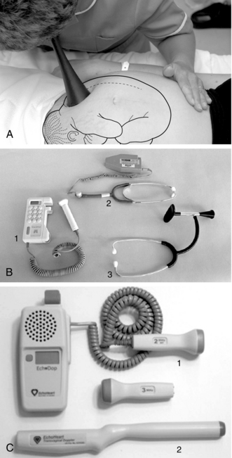
FIGURE 3-1 A. Auscultation of the FHR with a Pinard stethoscope. Vertex left occipitoanterior. B. 1, Ultrasound (US) fetoscope; 2, US stethoscope; 3, DeLee-Hillis fetoscope. C. 1, Echoheart transabdominal US transducer; 2, Echoheart transvaginal probe
(A. From Fraser DM, Cooper MA, editors: Myles textbook for midwives, ed 14, London, 2003, Churchill Livingstone. B. Courtesy Michael S. Clement, MD, Mesa, AZ. C. Courtesy EchoHeart, Inc., Damariscotta, ME.)
While electronic fetal monitoring is based on visual assessment, auscultation is an auditory assessment in which an instrument or device is used to count the number of fetal heartbeats occurring in a prescribed amount of time at specified intervals and in relation to uterine contractions. Clinicians must understand that IA is not simply electronic fetal monitoring without a tracing.6,9 There are significant differences between IA and EFM.2 These are summarized in Table 3-1.
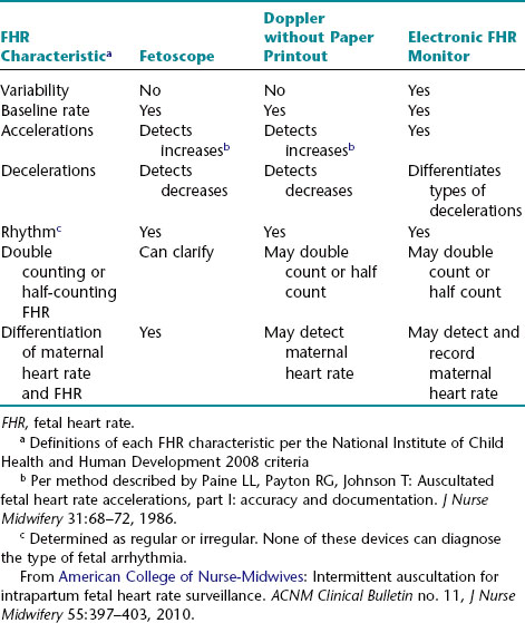
In addition to serving as the primary method of fetal assessment in labor, auscultation technique can assist clinicians with differentiation of maternal heart rate (MHR) from fetal heart rate, and with correct placement of the external Doppler transducer used in EFM.
| Procedure | Rationale |
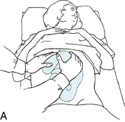
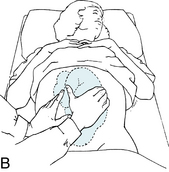
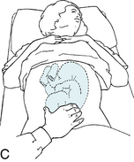
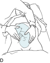
Leopold’s maneuvers
Utilization and frequency of intermittent auscultation
Many countries prefer intermittent auscultation to continuous electronic fetal monitoring in women without risk factors, as this promotes their mobility, is less distracting, and provides a more natural birthing experience without the use of electronic devices. Reliance on the electronic monitor is more prevalent in the United States, most likely because of staffing patterns, staffing mix, and the increased use of defensive practices in a litigious environment. The American College of Obstetricians and Gynecologists3 suggests continuous monitoring for patients with high-risk conditions, noting the uncertainty regarding the safety of IA in high-risk pregnancies. Regardless of the method used to assess the fetal heart rate, the standard practice is to evaluate and record the heart rate at specific intervals.1
The American College of Nurse-Midwives2 reviewed references from the United States, Canada, and Great Britain regarding the frequency of auscultation for low-risk women and found fairly consistent recommendations for auscultation frequency of every 15 minutes in the active phase of the first stage of labor and every 5 minutes in the second stage. Nursing guidelines regarding the length and specific timing of auscultation are discussed in detail by the Association of Women’s Health, Obstetric and Neonatal Nurses (AWHONN).9
Documentation of auscultated fetal heart rate
Documentation of the auscultated fetal heart rate must be accompanied by other routine parameters that are assessed during labor, including uterine activity, maternal observations and assessment, and both maternal and fetal responses to interventions. It should be noted how long the fetal heart rate was auscultated and whether this was before, during, and/or immediately after a uterine contraction. The rate, rhythm, and abrupt or gradual increases or decreases of the fetal heart rate during any part of this auscultated period should be described in relationship to uterine activity.
Note: It is not appropriate to describe auscultated fetal heart rate using the descriptive terms associated with electronic fetal monitoring because the majority of the electronic fetal monitoring terms are visual descriptions of the patterns produced on the monitor tracing (e.g., early, late, and variable decelerations or variability). However, terms that are numerically defined, such as bradycardia and tachycardia, can be used.2,6,9
Interpretation of auscultated fetal heart rate
Although the terms “reassuring” and “non-reassuring” are no longer used when electronic fetal monitoring is employed, they remain the commonly used summary terms for intermittent auscultation.9
Benefits and limitations of auscultation
Limitations
In summary, intermittent auscultation has been found to be effective if performed in a consistent manner by a clinician caring for a woman according to a prescribed frequency. Worldwide, auscultation is frequently and successfully employed as the first line of fetal assessment in low-risk populations. Nurses should be comfortable performing intermittent auscultation. Continued research regarding auscultation, especially research related to nurse/patient ratios and frequency of assessments in latent phase labor, could prove beneficial in the acceptance of auscultation in the United States.
Electronic fetal monitoring
Overview
Electronic fetal monitoring may be external or internal, or utilize a combination of both. The external mode employs the use of transducers placed on the maternal abdomen, to assess the fetal heart rate and uterine activity. The internal mode uses a spiral electrode (to assess the fetal heart rate) and an intrauterine pressure catheter (to assess uterine activity and intrauterine pressure). In some countries, electronic fetal monitoring is called cardiotocography or “CTG.” The following chart compares the external and internal modes of monitoring and gives a brief description of the equipment used for each.
| Fetal Heart Rate | |
| External Mode | Internal Mode |
| Ultrasound (Doppler) transducer: High-frequency sound waves reflect mechanical action of fetal heart. | Spiral electrode: Electrode converts fetal electrocardiogram (ECG) (as obtained from presenting part) to FHR via cardiotachometer by measuring consecutive fetal R-wave intervals. The cervix must be sufficiently dilated to allow placement. The electrode penetrates the fetal presenting part 1.5 mm, and it must be securely attached to ensure an adequate signal. |
| Uterine Activity | |
| External Mode | Internal Mode |
| Tocodynamometer (tocotransducer): This instrument monitors the approximate frequency and duration of contractions by means of a pressure-sensing device applied to the abdomen. | Intrauterine pressure catheter: This instrument monitors frequency, duration, and intensity of contractions and resting tone. The catheter is compressed during contractions, placing pressure on a transducer tip (or the strain gauge mechanism of a fluid-filled catheter) and then converting the pressure into millimeters of mercury (mm Hg) on the UA panel of the monitor tracing. The membranes must be ruptured and the cervix sufficiently dilated for placement. Catheters are available with a second lumen that can be used for amnioinfusion. |
Converting raw data into a visual display of FHR
The fetal heart rate data collected, whether by external or internal means, must then be converted into a visual display (Figures 3-3 and 3-4). This display may be on paper, a computer screen, or often both. Interpretation of electronic fetal heart rate monitoring is based on a visual assessment of data presented on a Cartesian graph. The gridlines on the horizontal (x) axis of the graph represent time in increments of 10 seconds. The gridlines on the vertical (y) axis represent the fetal heart rate in increments of 10 beats per minute. As illustrated in Figure 3-5, the fetal heart rate appears on the graph as an irregular horizontal line representing the fetal heart rate over a period of time.

FIGURE 3-3 Philips Avalon FM 50 fetal monitor provides measurement of the FHR including noninvasive triplet monitoring, FHR high/low audible and visual alarms, and FECG. Maternal parameters include toco and intrauterine pressure, blood pressure, pulse rate, pulse oximetry and ECG. It has cross-channel verification of maternal and fetal heart rate, displays FECG and MECG on the color display touch screen and has a LAN interface for compatibility with hospital IT networks.
(Courtesy Philips Medical Systems, Böblingen, Germany.)
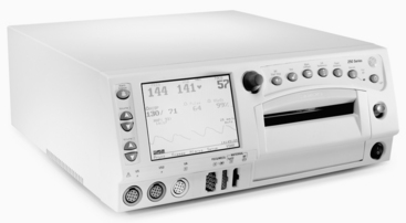
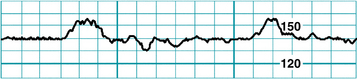
FIGURE 3-5 An FHR tracing has the appearance of an irregular horizontal line.
(Courtesy David A. Miller, MD.)
However, as demonstrated in Figure 3-6, closer inspection reveals that the “irregular horizontal line” is not a line at all. Instead, it is a series of individual, closely spaced points. Each point represents an individual heart rate that is calculated from the time between two successive heartbeats. This is a fundamental principle of electronic fetal heart rate monitoring and merits brief review.
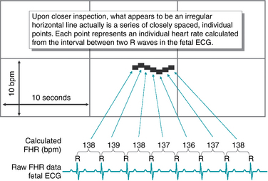
Fetal monitoring equipment used in clinical practice detects the fetal heartbeat in one of two ways. A fetal scalp electrode detects the actual electrical impulses that originate in the fetal heart and make up the fetal electrocardiogram. An external transducer uses Doppler ultrasound to detect cardiac motion. Regardless of the method of detecting the fetal heartbeat, the fetal heart rate monitor uses the same basic principles to process the raw data for visual display. If the fetal heart rate is derived from a direct fetal electrode detecting the fetal electrocardiogram, as illustrated in Figure 3-6, the monitor measures the distance between two successive R waves and calculates a heart rate based on that single R-R interval. The individual heart rate is plotted as a single point on the fetal heart rate graph. The monitor then measures the next R-R interval, calculates a new heart rate, and plots it as a new point on the graph. This process is repeated with every subsequent R wave. If the fetal heart rate is derived from an external Doppler ultrasound transducer, the monitor uses the peak of the Doppler waveform in place of the R wave and performs the same basic calculations. A normal fetal heart rate baseline rate of 140 beats per minute will yield approximately 140 individual graph points every minute, each representing an individual heart rate. To the eye, these individual points are spaced so closely together that they appear as a line. Variations in the fetal heart rate cause the line to appear irregular. The physiologic significance of these variations will be discussed in Chapter 5.
External mode of monitoring
Ultrasound transducer
Description
An ultrasound transducer is a device that is placed on the maternal abdomen and generates high-frequency ultrasound waves that are transmitted into the tissues (Figure 3-7). As the ultrasound waves strike tissue interfaces, some of the waves are reflected back toward the transducer from which they originated. The transducer detects the returning waves and converts them into electric signals. When ultrasound waves are reflected from a moving interface, such as the fetal heart, the waves return at different frequencies. This phenomenon is known as the Doppler effect. The change in frequencies can be used to calculate the motion of the target. As described previously, Doppler-detected fetal heart motion is converted to a continuous graphic display of fetal heart rate printed on the upper portion of the fetal heart rate monitor strip. Simultaneously, the Doppler-detected fetal heart rate is converted electronically to an audible beep and flashing light on the monitor.
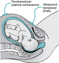
FIGURE 3-7 Placement of external transducers. The tocotransducer transmits UA. The US transducer transmits FHR.
(From Lowdermilk DL, Perry SE, Cashion K, et al: Maternity & women’s health care, ed 10, St. Louis, 2012, Mosby.)
The Doppler signal can be affected by changes in the position of the transducer or the fetus. Changes in the direction of the sound beam during contractions may cause a loss of signal and make the resulting tracing uninterpretable, and the transducer may need frequent repositioning due to maternal position changes. Artifact and erratic tracings may result from a number of causes, such as increased variability, halving or doubling of the fetal heart rate by the monitor, recording of maternal heart rate, fetal arrhythmias, and fetal or maternal movement.
Placement of ultrasound transducer
A sequential procedure with rationales is provided for the application of the ultrasound transducer.
| Procedure | Rationale |
|
13. Box 3-1
BOX 3-1 General Guidelines for Care, Cleaning, and Storage of External Transducers  Exercise caution when removing and handling the US and tocotransducers so that they are not dropped or allowed to swing against any equipment, to protect from damage. Clean transducers according to the manufacturer’s operating manual, usually with a soft cloth using mild soap and water. Avoid submerging transducers or placing them beneath running water. Do not use alcohol or other cleaning solutions that may damage equipment. Gently and loosely coil cables for storage. Avoid tight coiling and sharp bending of the cables, which will result in damage to the wires or casing. Exercise caution when removing and handling the US and tocotransducers so that they are not dropped or allowed to swing against any equipment, to protect from damage. Clean transducers according to the manufacturer’s operating manual, usually with a soft cloth using mild soap and water. Avoid submerging transducers or placing them beneath running water. Do not use alcohol or other cleaning solutions that may damage equipment. Gently and loosely coil cables for storage. Avoid tight coiling and sharp bending of the cables, which will result in damage to the wires or casing. |
Tocotransducer
Description
The tocotransducer (toco) monitors uterine activity transabdominally by means of a pressure-sensing button that is depressed by uterine contractions or fetal movement. The uterine activity panel of the monitor paper displays the frequency and duration of contractions. Intensity and resting tone can be assessed only with palpation or the use of an intrauterine catheter. Thus, palpation of contractions to assess strength is mandatory when using the toco.
Placement of tocotransducer
A sequential procedure with rationales is provided for the placement of the tocotransducer.
Advantages and limitations of external transducers
Limitations
US transducer (Doppler) may double-count a slow fetal heart rate of less than 60 bpm, resulting in an apparently normal fetal heart rate during a bradycardia; or it may half-count an elevated fetal heart rate of more than 180 bpm, resulting in an apparently normal fetal heart rate during a tachycardia. Maternal heart rate may be counted if the ultrasound transducer is placed over the maternal arterial vessels, such as the aorta.Internal mode of monitoring
Spiral electrode
Description
The spiral electrode monitors the fetal electrocardiogram from the presenting part. It is generally applied only after the membranes have been ruptured, although it may be applied through intact membranes when necessary.5 Additionally, the cervix must be sufficiently dilated to allow placement and the presenting part must be accessible and identifiable (Figure 3-8). Therefore the spiral electrode is used only during the intrapartum period.
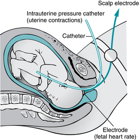
FIGURE 3-8 Diagrammatic representation of internal mode of monitoring with intrauterine pressure catheter and spiral electrode attach to fetal scalp.
(From Lowdermilk DL, Perry SE, Cashion K, et al: Maternity & women’s health care, ed 10, St. Louis, 2012, Mosby.)
Placement of fetal spiral electrode
Intrauterine pressure catheter
Description
The intrauterine pressure catheter or transducer (IUPC) monitors contraction frequency, duration, intensity, and resting tone (Figure 3-9). A small catheter is introduced through the vagina transcervically into the uterus after the fetal membranes have been ruptured and the cervix is sufficiently dilated to identify the presenting part. The catheter is compressed during uterine contractions, placing pressure on a transducer. The pressure is then reflected on the monitor tracing in units of millimeters of mercury (mm Hg).
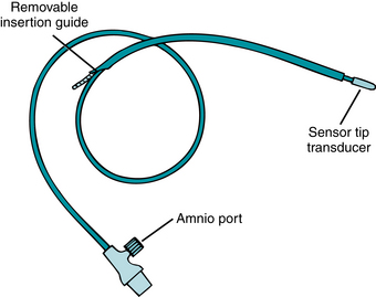
FIGURE 3-9 Intrauterine catheter with the sensor transducer located in the tip of the catheter provides uninterrupted UA monitoring. Saline-filled catheters are another type of catheter in use. Note that this catheter has an amnioport that may be used for amnioinfusion. The procedure of amnioinfusion is used to treat variable decelerations in the presence of oligohydramnios. See Appendix A for more information.
Intrauterine pressure catheters that have the pressure-sensing device within the catheter tip or cable do not require an instillation of sterile water for use. These catheters are provided with an amnioport to allow simultaneous amnioinfusion while monitoring uterine activity. Always refer to the manufacturer’s directions and guidelines, along with the facility’s policies and procedures, for information on use and insertion.
Placement of intrauterine pressure catheter
A licensed registered nurse may insert the intrauterine pressure catheter, but only if this is allowed by licensing board regulations and if the nurse is credentialed and approved by the institution’s policies. The following chart shows the procedure in a sequential format for the use and insertion of the intrauterine pressure catheter.
| Procedure | Rationale |
|
c. Advance only the catheter according to the insertion depth indicator or until the blue/black or stop mark on it reaches the vaginal introitus.*
|
|
| Fluid-filled catheters | |
| When monitoring is in progress. | |
* Remove catheter immediately in the event of extraovular placement outside of the amniotic fluid space (between the chorionic membrane and endometrial lining), as evidenced by blood in the catheter.
Advantages and limitations of internal monitoring
Limitations
A fetal monitoring equipment checklist (Table 3-2) can be used to check for and ensure proper functioning of the equipment. To allay any anxiety, the woman who is electronically monitored should be given an explanation of equipment operations and the possibility of need for adjustments during labor. The care given to the electronically monitored woman is the same as that given to any woman during labor, with the additional consideration of those factors that relate directly to the monitor.
TABLE 3-2 Fetal Monitoring Equipment Checklist
| Name: Evaluator: ______________________________________________________________________ |
| Date: ______________________________________ |
| Items to Be CheckedYes No Remarks |
| Preparation of Monitor |
| Ultrasound (US) Transducer |
| Tocotransducer |
| Spiral Electrode |
| IUPC |
Display of fetal heart rate, uterine activity, and other information
The display on the front of the monitor shows the fetal heart rate and the uterine pressure, and it identifies the signal source for each. Additional monitor options include maternal noninvasive blood pressure, maternal heart rate, maternal pulse oximetry, maternal electrocardiogram in real time, gross fetal body movements, and ST analysis (when using STAN®). These parameters are also displayed on the front or face of the monitor (Figure 3-10).

FIGURE 3-10 The monitor display shows the FHR and uterine activity and identifies the signal source for each. Other parameters may be displayed including maternal blood pressure, pulse rate, MECG, and pulse oximetry.
(Courtesy Philips Medical Systems, Böblingen, Germany.)
Other data, in addition to the fetal heart rate and uterine activity, may be printed on the monitor strip. The time of day, date, and paper speed are usually printed every 10 minutes. The signal source is usually printed on every three or four pages of the tracing and with each change of parameter and mode of monitoring. Depending on the monitor’s options, other maternal and fetal data may be printed on the tracing. The maternal heart rate and maternal electrocardiogram can be trended on the upper (or heart rate) section of the monitor strip. Maternal noninvasive blood pressure can also be printed as whole numbers. The manufacturer’s operating manual should be available and referred to for more information, especially when assessing women with risk factors who may have concurrent monitoring of multiple parameters.
Monitor tracing scale
The fetal heart rate and uterine activity are printed on scaled paper (Figure 3-11). The fetal heart rate is printed on the upper section and the uterine activity on the lower section. Monitors are preset by their manufacturers for the countries in which they are used. Note the differences in the range and scale of the fetal heart rate and uterine activity sections, as well as in the paper/recorder speed, in Figure 3-12. The monitor strip in Figure 3-12, A, depicts the tracing paper that is used with monitors used in North America, with a speed of 3 cm/min. The monitor strip in Figure 3-12, B, depicts the tracing paper that is used in many countries outside North America, with a speed of 1 cm/min. It is imperative to use tracing paper that is designed in the correct scale to match the monitor settings.
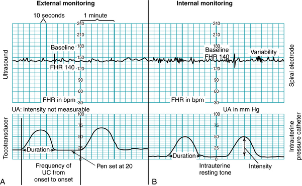
FIGURE 3-11 Fetal monitor display of FHR and UA. A, Monitor strip of external mode with ultrasound and toco as the signal source; B, Monitor strip of internal mode with spiral electrode and intrauterine catheter as the signal source.
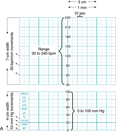
FIGURE 3-12 A. Fetal monitor paper scale: 3 cm/min speed used in North America.
| Vertical Axis | |
| Heart Rate | |
| Range | 30 to 240 bpm |
| Scale | Increments of 10 bpm (30 bpm/cm) |
| Uterine Activity | |
| Range | 0 to 100 mm Hg pressure |
| Scale | Increments of 10 mm Hg |
| Horizontal Axis | |
| Paper/recorder speed | 3 cm/min = six 10-second subsections within 1 minute |
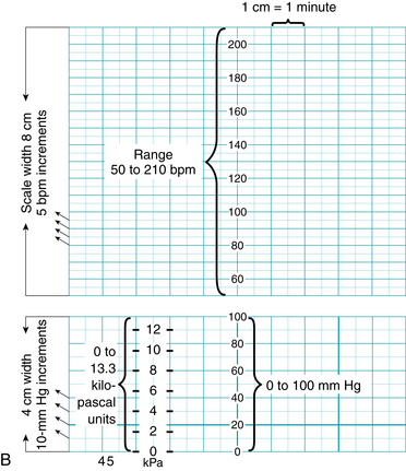
B. Fetal monitor paper scale: 1 cm/min speed used in countries outside North America, with key points identified.
| Vertical Axis | |
| Heart Rate | |
| Range | 50 to 210 bpm |
| Scale | Increments of 5 bpm (20 bpm/cm) |
| Uterine Activity | |
| Range | 0 to 100 mm Hg pressure, or 0 to 13.3 kilopascal units (1 kPa = 7.5 mm Hg) |
| Scale | Increments of 10 mm Hg |
| Horizontal Axis | |
| Paper/recorder speed | 1 cm/min = 2 subsections (or 2 cm/min speed = four subsections) |
Monitoring twins and multiples
Many monitors have the capability of monitoring twin or multiple gestations at the same time. Monitoring of twins may be done with two separate ultrasound transducers, or one fetus may be monitored by direct fetal scalp electrode (Figure 3-13). The dual tracings may be distinguished by a thicker or darker trace for one fetus and a thinner or lighter trace for the other fetus (Figure 3-14). Another option to distinguish the tracings between twins is a “twin offset” mechanism, which separates the two fetal heart rates on the tracing by a distance of about 20 beats per minute. Thus one twin appears to have a fetal heart rate that is higher than the actual heart rate. The manufacturer’s instruction manual should be consulted to have a clear understanding of this capability.
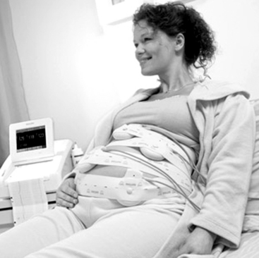
FIGURE 3-13 Monitoring of multiple gestations with separate US transducers. (Courtesy Philips Medical Systems, Böblingen, Germany.)
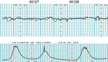
FIGURE 3-14 Dual US heart rate monitoring strip demonstrates the simultaneous external monitoring of twins.
(Courtesy GE Medical Systems Information Technologies, Milwaukee, WI.)
To clearly differentiate between twins, their positions in the uterus can be documented and ultrasound transducers labeled. The cross-channel verification alert may occur if both fetuses have the same/coincidental heart rates. If this occurs, relocate the tocotransducer(s) to detect the second fetal heart rate. In identifying twins or multiples, the fetus in the advanced position just above the cervix is labeled A, the next one B, and so on.
Artifact detection & signal coincidence with MHR
Fetal monitors have built-in artifact rejection systems, which are always in operation when using the external mode of fetal heart rate monitoring. Logic circuitry rejects data when there is a greater variation than is expected between successive fetal heartbeats. When repetitive variations vary by more than the accepted amount, newer monitors continue to print regardless of the extent of the excursion of the fetal heart rate. The older generation of monitors may switch from a hold mode to a non-record mode. The recorder resumes recording when the variations between successive beats fall within the predetermined parameters.
During internal monitoring, artifact is rare, and the logic system will miss only those changes that exceed the predetermined limits of the system. If there is an accessible switch to select a logic or no-logic mode, it is preferable to have the monitor in the no-logic mode when using the internal mode (spiral electrode) to detect fetal arrhythmias.
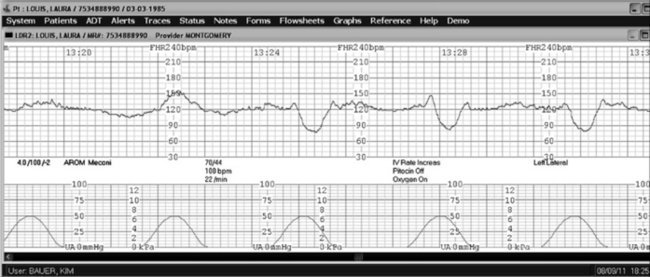
Signal coincidence with maternal heart rate can occur when using the external Doppler method, especially during second stage when MHR may become elevated during pushing. There are a number of case reports involving adverse fetal outcomes, including fetal demise in utero, which occurred following signal ambiguity where it was impossible to recognize the shift from the fetal heartbeat to maternal on the tracing printout15 (Figure 3-15).
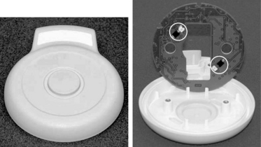
FIGURE 3-16 The modified Toco transducer M2734B, `Toco MP,´ allows automatic maternal pulse detection and automatic coincidence detection via cross-channel verification that confirms both maternal and fetal signals.
(Courtesy Philips Medical Systems, Böblingen, Germany)
At the time of this writing, a new tocodynamometer has been developed by Philips that allows automatic maternal pulse detection and automatic coincidence detection using cross-channel verification, allowing confirmation of both maternal and fetal signals without use of maternal pulse oximetry or manual confirmation. (Figure 3-16).
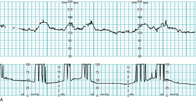
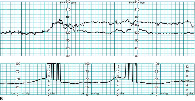
FIGURE 3-15 A. Example of a FHR tracing showing maternal heart rate being recorded as fetal, note appearance of “accelerations” with maternal pushing efforts. B. Now FHR tracing shows both the actual fetal heart rate (upper tracing line) concomitantly with the maternal heart rate (lower tracing line). Maternal heart rate accelerations are seen with pushing efforts.
Telemetry
Remote internal or external fetal heart rate monitoring via radio wave telemetry (Figure 3-17) helps women remain ambulatory without the loss of continuous monitoring data. A woman may feel less confined, more relaxed, and more content if she can walk around. The transducer is worn by means of an abdominal belt or other device. Heart rate and uterine activity signals are continuously transmitted to a receiver that is connected to the fetal monitor. The monitor then processes and displays the data, and it prints the heart rate and uterine activity on the monitor strip. Use of a central display facilitates clinician surveillance of the telemetry-monitored patient.
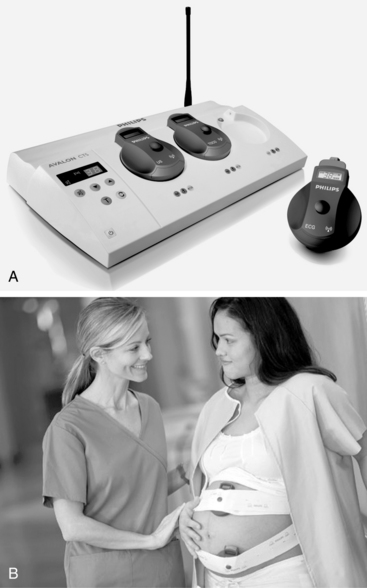
FIGURE 3-17 A. The cordless transducer system (Avalon CTS) transmits information to a base station and prints fetal and uterine activity on a fetal monitor strip. Waterproof transducers may be used for the patient who is in bed, ambulating, or in the bath. B. Cordless US and tocotransducer are applied to the maternal abdomen for external monitoring.
(Courtesy Philips Medical Systems, Böblingen, Germany.)
In addition to standard ultrasound and tocotransducers, external watertight transducers are available. These can be used to continue fetal surveillance during hydrotherapy or waterbirth.
Troubleshooting the monitor
The electronic fetal monitor is a useful tool to assess fetal well-being. As with any electronic device, problems may occur, but they can often be overcome. A fetal monitoring equipment checklist (see Table 3-2) can be used to screen for appropriate application of the monitor. The following chart suggests actions for identified electro-mechanical problems.
| Problem | Action |
| Power | Check power cord at wall and back of monitor. |
| Ultrasound | |
| Half or double rate | |
| Erratic trace or display | |
| Spiral electrode | |
| Erratic trace or display | |
| Signal quality indicator is continuously red | |
| Tocotransducer | |
| Not recording | |
| Numbers in high range | |
| Toco not picking up contractions | |
| Intrauterine pressure catheter | |
| Not recording | |
| Resting tone (>25 mm Hg) | |
| Not recording contractions | |
| Elevated resting tone (hypertonus) | |
| Potential problems | |
| Suspected fetal arrhythmia | |
| Errors caused by incorrect paper speed or paper with different scale | |
| Cross-channel verification alert |
Computerized perinatal data systems
Many institutions utilize computerized perinatal data systems that provide central surveillance, alerts, documentation, and archiving capabilities electronically. A central monitor display at the nurses’ station provides an opportunity to view tracings from several women at the same time (Figure 3-18), while single-screen displays of several women or of one woman can be accessed from remote locations, including the bedside, the staff locker room or lounge area, the physician’s office, or at home. Clinicians can have access to the monitor tracings from multiple patients and from a variety of locations. Perinatal data systems include the capability of real-time data entry in the form of detailed notes about examination results, cervical dilation, fetal station, administration of drugs, the woman’s position, and vital signs. Newer perinatal data systems offer universal electronic health records (EHRs) that incorporate the entire perinatal and neonatal spectrum, from prenatal care through delivery, as well as postpartum and neonatal care. Reports and “paper charts” can be generated with a printer linked to the display or shared electronically through the healthcare institution’s intranet.

FIGURE 3-18 Central display for EFM allowing access to multiple records in a variety of formats.
(Courtesy Philips Medical Systems, Böblingen, Germany.)
The majority of central display systems provide multiple options for accessing and viewing information (Figure 3-19), including the following:
A system status screen provides an instant overview of several beds on the system and indicates any alerts by room number. In addition, it can identify the signal source of any woman on the system. A trend screen can provide the most recent few minutes of heart rate and UA data on any one woman, with immediate warning of critical conditions relating to any woman in the system. Scrolling capabilities allow clinicians to review hours of FHR data in minutes, which can help identify changes over time, an important component of FHR tracing evaluation. An alert screen can provide an immediate summary of the trend analysis on any woman. The data can be made available to the staff before, during, and after an alert.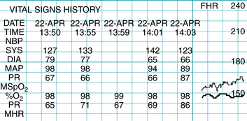
FIGURE 3-19 Clinicians can review and print trending data, such as the history of maternal blood pressure readings, and quickly determine status changes.
(Courtesy GE Healthcare, Milwaukee, WI.)
The surveillance component of a perinatal data system can be set to alert for fetal tachycardia or bradycardia, signal loss, coincidental fetal and maternal heart rates, and other parameters. Ranges for the duration of, and recovery from, fetal bradycardia or tachycardia can be set at different levels for each patient. These systems are widely available from a variety of companies.
In addition to improving the quality of care through surveillance and alert capabilities, these systems provide database access for statistical reporting for administration, research, and quality purposes, especially when integrated with other hospital or outpatient information systems. This advance allows multiple data entry points across the continuum of care and serves to link care and services provided at different sites within the healthcare/hospital network.13 For example, if a woman presents to the birthing center in the middle of the night, the staff can readily access the entire antenatal record, the ultrasound report, nonstress test, and biophysical profile that were completed just the previous afternoon, even if performed at a different campus within the system. Additionally, some systems allow clinicians to access information and review fetal heart rate tracings using cellular phone displays (Figure 3-20).
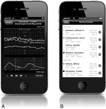
FIGURE 3-20 Providers can access near real time FHR tracings and review patient data using their mobile phones. A. FHR tracing, including MHR. B. Patient listing.
(Courtesy AirStrip Technologies, Inc., San Antonio, TX.)
Electronic documentation on forms and flow sheets, together with annotated tracings and automated data acquisition of information such as maternal blood pressure and pulse, result in a complete and detailed electronic health record. The archival and retrieval of the original fetal monitoring tracings has proved to be a problem for most medical record departments because the process is labor intensive and the paper is space consuming and subject to deterioration. Microfiche records are less bulky to store but still take time to log, sort, and file in the medical record, although some facilities continue to do this. Computer-based electronic storage systems provide secure archival and retrieval options, and can help prevent loss or destruction of fetal monitoring data.
The ability to have multiple points of data entry, information retrieval, and reproduction of a woman’s record and fetal monitor tracing is a significant advancement. Coupled with an interface to the hospital admission, discharge, and other hospital-based information systems, it is contributing to the trend toward comprehensive, paperless, and fully electronic information systems.
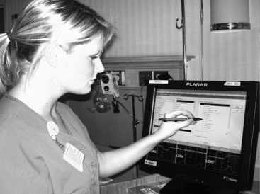
Data-input devices
Electronic perinatal data systems may use a variety of data-input devices, including bar-code readers, keypads for data entry, light-pens (Figure 3-21), touch screens, remote event markers, and standard computer keyboards. The input is subsequently printed on the tracing (Figure 3-22). The use of these options can promote accurate documentation and help eliminate the need for handwritten annotations, which are sometimes illegible. Additionally, ongoing information important to documentation such as the time, date, paper speed, and signal source is routinely entered on the monitor strip automatically. For more on documentation and health information technology, see Chapter 10.
Abdominal fetal electrocardiogram (fECG) and st segment analysis
Two relatively recent arrivals to electronic fetal monitoring in the United States are the Monica AN24® monitor, an external fetal heart rate monitoring solution that uses abdominally obtained electrical impulses to monitor FHR and uterine activity; and the STAN® monitor, which offers both external and internal fetal monitoring capability with the additional option of ST segment analysis for select patients using a specialized fetal scalp electrode.
Abdominal fECG and electromyogram (EMG)
Abdominal fECG is not new and was used as a standard monitoring modality in fetal monitors sold in the 1970s. But problems with reliability and advances in Doppler technology soon made Doppler ultrasound the standard external monitoring choice in the 1980s, and this has remained the norm in the United States. But as discussed earlier, Doppler technology continues to suffer from reliability problems, for two principal reasons: the separation of the fetal from the maternal heart rate, and the loss of signal during maternal position changes or fetal movement. In 2011, a new abdominal fECG monitor was introduced in the United States that offers solutions to these and other drawbacks of standard EFM.
The Monica AN24® uses 5 electrodes placed on the pregnant abdomen to directly monitor the electrocardiogram from the fetal and maternal heart and the electromyogram (EMG) from the uterine muscle (Figure 3-23). Fetal and maternal heart rates and uterine activity are extracted within the device and transmitted wirelessly, via Bluetooth technology, to an interface device that allows the FHR data and uterine activity data to print or display on a standard commercial fetal monitor and central display14 (Figure 3-24).
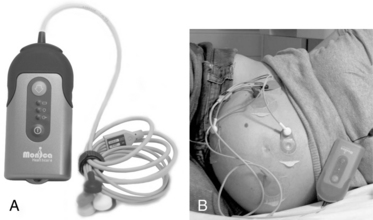
FIGURE 3-23 A. Monica AN24 is a wireless and beltless device that can be used with existing monitors to obtain FHR via abdominal ECG. B. Electrodes placed on maternal abdomen monitor ECG from fetal and maternal heart, and the electromyogram (EMG) from the uterine muscle.
(Courtesy Monica Healthcare Ltd, Nottingham, UK.)
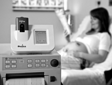
FIGURE 3-24 Monica AN24 docking station on top of Corometrics fetal monitor is connected via Monica IF24 Interface Device.
(Courtesy Monica Healthcare Ltd, Nottingham, UK and GE Medical System Information Technologies, Milwaukee, WI.)
The Monica AN24® simultaneously monitors the electrophysiologic signals on three separate channels spanning the abdomen, following fetal movement changes and using a sophisticated method to uniquely identify the maternal ECG and subtract it from the signal leaving only the fetal ECG complex.11,12 This eliminates much of the problem with fetal movement and signal interruption as well as maternal-fetal signal coincidence. Additionally, adipose tissue has less of an impact on the electrical signals monitored on the abdomen than it does on the transmission of ultrasound, so there is less signal loss in patients with elevated body mass indices (BMI).
The uterine activity is a reflection of the electromyogram (EMG), electrical activity produced by uterine muscle.12 EMG data allows increased accuracy related to frequency, occurrence of peak, and duration over traditional pressure-sensitive toco transducers, but does not provide actual intensity measurement in mm Hg as with an intrauterine pressure catheter. Although clinicians will continue to assess contraction strength and uterine resting tone using palpation, the Monica AN24® eliminates the need for belts and frequent toco readjustments common in traditional monitoring. The wireless capabilities provide similar range to those seen with cell phone Bluetooth headsets, providing patient mobility of approximately 50 feet (15 meters) from the base, allowing for a variety of maternal activities during labor (Figure 3-25).
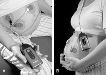
FIGURE 3-25 A, Woman sitting on birthing ball and B, woman ambulating, both wearing the Monica AN 24.
(Courtesy Monica Healthcare Ltd, Nottingham, UK.)
Benefits of the abdominal fECG and EMG approach include improved signal quality, elimination of maternal-fetal signal coincidence, and maternal mobility and comfort; however, the method cannot be used during hydrotherapy or waterbirth. While availability of the fetal ECG non-invasively is a clear benefit, there are some fetuses that generate a very poor fetal ECG as measured on the abdomen and cannot be monitored with this technology. Additionally, there are some limitations applicable only to the U.S. market, with FDA approval restricted to use in gestations of 36 completed weeks or greater, and lack of FDA approval for display of maternal heart rate (it is captured and separated from the fetal heart rate but not displayed). It should be noted that at time of this writing, approval for the display of maternal heart rate data was in process.
St segment analysis
When using internal fetal monitoring, clinicians may now access information regarding the ST segment of the fetal electrocardiogram during labor with an ST waveform analyzer (STAN®; Neoventa Medical, Göteborg, Sweden) that serves as an adjunct to standard EFM. Using a combination of strict FHR interpretation/management guidelines and ST waveform analysis, STAN® provides clinicians with information on the fetal myocardial response to hypoxia based on fetal electrocardiogram changes, specifically changes in the ST interval.4,7,8,16
The STAN® system consists of a freestanding electronic fetal monitor with a special ST analysis feature (Figure 3-26). The monitor can be used with or without ST analysis, functioning as a standard fetal monitor with all gestational ages; however, use of the adjunctive ST analysis option requires several patient characteristics be met, which are as follows:
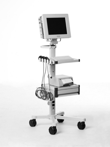
FIGURE 3-26 The STAN® S31 fetal monitor, capable of both traditional EFM and adjunctive ST waveform analysis for selected patients has a 15-inch touch color display providing for a convenient review of traces.
(Courtesy Neoventa Medical, Mölndal, Sweden.)
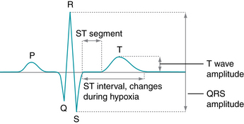
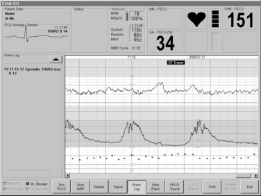
Following appropriate patient selection, a special scalp electrode is applied (Figure 3-27) and fetal electrocardiogram data are analyzed to evaluate the T/QRS ratio and the ST interval (Figure 3-28). These data are evaluated and appear on the monitor screen below the electronic fetal monitoring tracing (Figure 3-29). Clinicians apply strict classification and analysis guidelines4,7 to determine the fetal response to hypoxia and subsequent labor management. Further information on STAN® as an adjunct to electronic fetal monitoring, including clinical trials, is presented in Chapter 6.

FIGURE 3-27 Applied spiral scalp electrode and skin electrode.
(Courtesy Neoventa Medical, Mölndal, Sweden.)
Summary
Fetal monitoring can be safely accomplished in a variety of ways, from simple auscultation and palpation to internal electronic monitoring using analysis of the fetal ECG. The obstetric team includes the patient and her support system. A discussion of monitoring options, as well as patient education regarding the selection of methodology is an important part of collaborative care. Regardless of the technique chosen, clinicians must understand the proper application, care, and use of related equipment, benefits, and limitations of the various options, and patient selection criteria.
1. American Academy of Pediatrics, American College of Obstetricians and Gynecologists. Guidelines for perinatal care, ed 6. Washington, DC: AAP, ACOG; 2007.
2. American College of Nurse-Midwives. Intermittent auscultation for intrapartum fetal heart rate surveillance. ACNM Clinical Bulletin no. 11. J Nurse Midwifery. 2010;55:397-403.
3. American College of Obstetricians and Gynecologists: Intrapartum fetal heart rate monitoring: nomenclature, interpretation, and general management principles. Practice Bulletin no. 106. Obstet Gynecol. 2009;114:192-202
4. Amer-Wåhlin I, Miller LA: ST analysis as an adjunct to electronic fetal monitoring: an overview. J Perinat Neonatal Nurs. 2010;24(3)231-237
5. Association of Women’s Health, Obstetric and Neonatal Nurses. Amniotomy and placement of internal fetal spiral electrode through intact membranes. AWHONN Position Statement. J Obstet Gynecol Neonatal Nurs. 2009;38:740.
6. Association of Women’s Health, Obstetric and Neonatal Nurses: Fetal heart monitoring: principles and practices, principles and practices. Dubuque, IA; Kendall Hunt: 2009
7. Belfort MA, Saade GR: ST segment analysis as an adjunct to electronic fetal monitoring, part I: background, physiology, interpretation. Clin Perinatol. 2011;38:143-157
8. Belfort MA, Saade GR: ST segment analysis (STAN) as an adjunct to electronic fetal monitoring, part II: clinical studies and future directions. Clin Perinatol. 2011;38:143-157
9. Feinstein NF, Sprague A, Trepanier MJ. Fetal heart rate auscultation, ed 2. Washington DC; AWHONN: 2008
10. Goodwin L: Intermittent auscultation of the fetal heart rate: a review of general principles. J Perinat Neonatal Nurs. 2000;14(3)53-61
11. Graatsma E, Jacod B, van Egmond L, et al: Fetal electrocardiography: feasibility of long-term fetal heart rate recordings. BJOG. 2009;116:334-338
12. Jacob BC, Graatsma EM, Van Hagen E, Visser GH. A validation of electrohysterography for uterine activity monitoring during labour. J Matern Fetal Neonatal Med. 2010;23(1):17-22.
13. Kelly CS: Perinatal computerized patient record and archiving systems: pitfalls and enhancements for implementing a successful computerized medical record. J Perinat Neonatal Nurs. 1999;12(4)1-14
14. Monica IF24 training guide. Monica Healthcare. Available at www.monicahealthcare.com/downloads/, June 5, 2011. Accessed
15. Neilson DR, Freeman RK, Mangan S. Signal ambiguity resulting in unexpected outcome with external fetal heart rate monitoring. Am J Obstet Gynecol. 2008;198(6):717-724.
16. Rosen KG, Lindencrantz K. STAN—the Gothenburg model for fetal surveillance during labour by ST analysis of the fetal electrocardiogram. Clin Phys Physiol Meas. 1989;10(Suppl B):51-56.