Sensory Aids for Persons With Auditory Impairments
FUNDAMENTAL APPROACHES TO AUDITORY SENSORY AIDS
Augmentation of an Existing Pathway
Use of an Alternative Sensory Pathway
AIDS FOR PERSONS WITH AUDITORY IMPAIRMENTS
Electroacoustical Parameters of Hearing Aids
Basic Structure of Hearing Aids
Types of Hearing Aid Signal Processing
Transmission of Power and Data
Telephone Access for Persons Who Are Deaf
Telephone Devices for the Deaf
Visual Telephones for the Deaf
Technology for Face-to-Face Communication Between Hearing and Deaf Individuals
Alerting Devices for Persons With Auditory Impairments
Captioning as an Auditory Substitute
Closed-Captioned Television and Movies
Real-Time Captioning for Education and Business Applications
Captioning by Automatic Speech Recognition
Basic Principles of Computer Adaptations for Auditory Impairments
Built-in Options to Increase Usability by Persons Who Are Deaf
Access to the Internet When Auditory Information Is Difficult for the User
Aids for Persons With Both Visual and Auditory Impairments
Devices for Face-to-Face Communication With Individuals Who Are Deaf and Blind
On completing this chapter, you will be able to do the following:
1 Describe the major approaches to sensory substitution, including the advantages and disadvantages of each
2 Describe the design and specification of hearing aids
3 Describe adaptations of common devices for use by a person who is hard of hearing or deaf
4 Discuss the major approaches used to provide input for individuals who have both visual and auditory impairments
5 Describe how computer outputs are adapted for individuals with auditory limitations
When an individual has a sensory impairment, assistive technologies can provide assistance in the input of information. This chapter emphasizes approaches that are used to either aid or replace seeing and hearing. This chapter is restricted to sensory aids that are intended for general use. Chapter 8 discusses assistive technologies that are designed to assist people who have visual limitations. This chapter focuses on assistive technologies designed to meet the needs of persons with auditory limitations.
FUNDAMENTAL APPROACHES TO AUDITORY SENSORY AIDS
Chapter 8 describes the fundamental approaches to sensory aids. Figure 8-1 applies to auditory as well as visual sensory aids. Augmentation of an existing pathway and use of an alternative pathway are the two basic approaches to sensory assistive technologies. When applied to the auditory system, the alternative pathways are tactile and visual. Each of these approaches is discussed in this chapter.
Augmentation of an Existing Pathway
When someone is hard of hearing, the primary pathway (i.e., the one normally used for input) is still available; it is just limited. Insufficient intensity means that the signals are too weak to be heard, and an amplifier is required. Certain frequencies may be more limited than others for people who are hard of hearing, and the hearing aid must be designed or specified to take this into account. For example, in aging there is usually a greater hearing loss in high rather than low frequencies. Augmentation of the auditory pathway is by use of hearing aids, cochlear implants, or assistive listening devices.
Use of an Alternative Sensory Pathway
There are two alternate sensory pathways available to someone who is deaf. The most common example is the use of manual sign language (visual substitution for auditory). Chapter 8 discusses the fundamental differences among the tactile, visual, and auditory systems.
Tactile Substitution.
Substitution of tactile input for auditory information differs from the substitution of tactile input for visual information (i.e., braille). One major difference is that the rate at which the auditory information changes is relatively high compared with the time required for the tactile system to input information. Engineers refer to this as the relative bandwidths of the two systems. The auditory system has a broader bandwidth (more information can be handled in a given amount of time) than the tactile system. Because auditory information is a sequence of sounds, these must be translated into tactile information for presentation to the user. These tactile signals are then detected and assembled into meaningful units by the central nervous system. Because the tactile system requires spatial and temporal information, its rate of input is slower than for the auditory system. Another major limitation of the tactile system for auditory input is that it lacks a means of converting sound (mechanical vibrations) into neural signals. This is the function normally carried out by the cochlea.
The only tactile method for input of auditory information that has been successful is the Tadoma method used by individuals who are both deaf and blind. In this method, which was used by Helen Keller, the person receives information by placing his or her hands on the speaker’s face, with the thumbs on the lips, index fingers on the sides of the nose, little fingers on the throat, and other fingers on the cheeks. During speech, the fingers detect movements of the lips, nose, and cheeks and feel the vibration of the larynx in the throat. Through practice, kinesthetic input obtained from these sources is interpreted as speech patterns. One reason for the success of this method is that there is a fundamental relationship between the articulators (reflected in the movements of the lips, nose, and cheeks) and the perceived speech signal, and this relationship is at least as important as the acoustic information (pitch and loudness) in the speech signal for individuals using the Tadoma method (Lieberman, 1967).
Visual Substitution.
Visual displays of auditory information can take several forms. One example, sometimes used in speech therapy or as an aid to deaf individuals who are learning to speak, is to display a picture of the speech signal on an oscilloscope-like screen. Often a model pattern portraying the ideal is placed on the top half of the screen, and the pattern from the person learning to speak is placed on the bottom half of the screen. The learner attempts to match the model through practice. Some current devices also use computer graphics to make the process more interesting and motivating. This type of sensory substitution of visual for auditory information is a rehabilitative technology that is not practical for assistive technologies. The reasons for this parallel those presented for the Stereotoner in relation to auditory substitution for vision (see Chapter 8).
Visual substitution for auditory information has been successful in several areas. These include visual alarms (e.g., flashing lights when a telephone or doorbell rings) and the use of text labels for computer-generated synthetic speech. Speech is the most natural auditory form of language. Likewise, written text is the most natural way of presenting visual language. Thus, a major design goal for assistive devices that use visual substitution for auditory communication is to provide speech-to-text conversion. In this type of device, speech is received and converted by computer to text and displayed so that the person with an auditory impairment can read it.
AIDS FOR PERSONS WITH AUDITORY IMPAIRMENTS
Helen Keller, who was both deaf and blind, is reported to have been asked whether she would prefer to have her vision or her hearing if she could have one or the other. She responded that she would prefer to have her hearing because she felt that people who are blind are cut off from things, whereas those who are deaf are cut off from people. It is important to keep this concept in mind in the following discussion of aids for persons who are deaf or hard of hearing. Auditory impairment is often not as obvious as visual impairment, and society does not view it as having the same degree of significance as visual impairment. It is natural for a person to wear glasses as a part of the inherent process of aging. However, many people are embarrassed to admit hearing loss sufficient to require a hearing aid. Despite these considerations, hearing loss is significant, and it can be socially isolating. Assistive technologies can provide great improvement in the lives of persons who have either partial or total auditory impairments.
Hearing Aids
Hearing aids are often conceived of as simple devices that amplify sound, primarily speech. Although hearing aids do contain amplifiers, hearing loss is rarely consistent across the entire speech frequency range. As discussed in Chapter 3, hearing loss is generally greater at some frequencies than at others. This presents a problem in the design of hearing aids. If all frequencies are amplified the same amount, the sound will be unnatural to the user. An additional difficulty encountered in providing hearing aids of high fidelity is that the components are small, and this miniaturization can limit the frequency response of the microphone and speaker, further reducing the quality of the aided speech.
Approximately 60% of the acoustic energy of the speech signal is contained in frequencies below 500 Hz (Berger, Hagberg, and Rane, 1977). However, the speech signal contains not only specific frequencies of sound but also the organization of these sounds into meaningful units of auditory language (e.g., phonemes), and more than 95% of the intelligibility of the speech signal is associated with frequencies above 500 Hz. For this reason, speech intelligibility rather than sound level is often used as the criterion for successful application of hearing aids.
Electroacoustical Parameters of Hearing Aids.
Hearing aid output is typically specified in decibels (dB) referred to a standard of 20 micropascals (see the discussion of sensory function in Chapter 3). Sound pressure level (SPL) is used to designate this parameter. Standards for hearing aid specification have been developed by the American National Standards Institute (S3.46, 1997; http://web.ansi.org/) and the International Electrotechnical Commission (60 118-0-10; http://www.iec.ch/). These standards allow for the comparison of hearing aids from different manufacturers, and they specify parameters that are used in this comparison.
When hearing aids are fitted, it is important to know the output levels from the hearing aid that are delivered to the listener. Average conversational speech can range from 40 to 80 dB SPL depending on both how far away the talker is from the listener and the talker’s vocal effort (Olsen, 1988). Therefore, the hearing aid output is assessed in response to a variety of input types and levels (e.g., pure tones and speech or speech-like signals). Powerful hearing aids are capable of producing output SPLs of 130 to 140 dB. These levels can damage the hearing mechanism even if the duration of the input is short. Therefore, the maximum power output of a hearing aid also needs to be specified to ensure that the level of the hearing aid output will not cause further hearing loss. Readers interested in the electroacoustical performance and measurement of hearing aids are referred to Dillon (2001) for a thorough review.
Types of Hearing Aids.
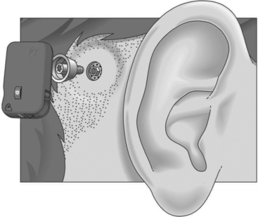
Conventional hearing aids can be divided into two types: air conduction and bone conduction. All air conduction hearing aids deliver the hearing aid output into the listener’s ear canal. However, some people are unable to wear air conduction hearing aids as a result of chronic ear infections or malformed ear canals. For these individuals, a bone conduction hearing aid is most appropriate. The most common type of bone conduction hearing aid is a BAHA (bone-anchored hearing aid) (Figure 9-1). Inputs to this type of hearing aid are converted to mechanical vibrations that shake the skull. BAHAs take advantage of the fact that, at a sensory level, it does not matter whether sounds come from an air-conducted hearing aid or a bone-conducted hearing aid. An air-conducted and a bone-conducted 1000-Hz tone will sound the same provided they are both at the same level of audibility. Snik et al (2005) provide a review of consensus statements regarding BAHAs.
Air conduction hearing aids are available in several different configurations (Stach, 1998). Figure 9-2 illustrates several commonly used types of aids. The major types of ear level aids are behind-the-ear (BTE), in-the-ear (ITE), in-the-canal (ITC), and completely-in-the-canal (CIC) aids. Body-level aids are used in cases of profound hearing loss. The processor is larger to accommodate more signal processing options and greater amplification and is mounted at belt level. The body-level aid is usually used only when other types of aids cannot be used
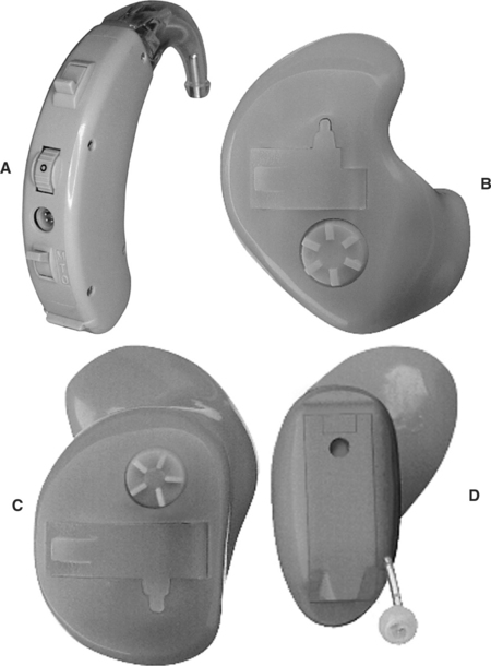
Figure 9-2 Types of hearing aids. A, Behind the ear (BTE). B, In-the-ear (ITE). C, In-the-canal (ITC). D, Completely in-the-canal (CIC). (Courtesy Siemans Hearing Instruments, Inc.)
BTE hearing aids, which fit behind the ear, contain all the components shown in Figure 9-3. The amplified acoustical signal is fed into the ear canal through a small ear hook that extends over the top of the auricle and holds the hearing aid in place. A small tube directs the sound into the ear through an ear mold that serves as an acoustical coupler. This ear mold is made from an impression of the individual’s ear to ensure comfort to the user, maximize the amount of acoustical energy coupled into the ear, and prevent squealing caused by acoustic feedback. When the mold is made, a 2-ml space is included between the coupler and the eardrum. A vent hole can also be added to an ear mold, which can add to acoustical feedback and distortion and preventing the ear from being blocked. The vent hole allows sound to travel to the tympanic membrane directly. An external switch allows selection of the microphone (M), a telecoil (T) for direct telephone reception, or off (O). The MTO switch and a volume control are located on the back of the case for BTE aids.
The ITE aid makes use of electronic miniaturization to place the amplifier and speaker in a small casing that fits into the ear canal. The faceplate of the ITE aid is located in the opening to the ear canal. The microphone is located in the faceplate. This provides a more “natural” location for the microphone because it receives sound that would normally be directed into the ear (Stach, 1998). External controls on the ITE include an MTO switch and volume control. The ITC is a smaller version of the ITE. The CIC type of hearing aid is the smallest, and it is inserted 1 to 2 mm into the canal with the speaker close to the tympanic membrane. Because this type does not protrude outside the ear canal, it is barely visible. Any controls for the aid are fit onto the faceplate of the ITE, ITC, and CIC types of aids.
Basic Structure of Hearing Aids.
Figure 9-4 illustrates the basic components of analog and digital hearing aids. The microphone is the environmental sensor; it is the component that receives the speech signal. Overall fidelity of the hearing aid is directly related to the quality of this component. Several types of microphones are used in hearing aids (see Stach, 1998). The function of the microphone is to convert the acoustical speech waveform into an electrical signal, which is sent to the amplifier. Microphones may be omnidirectional (amplify sound from any direction) or directional. They also include noise reduction properties to obtain the best input signal possible.
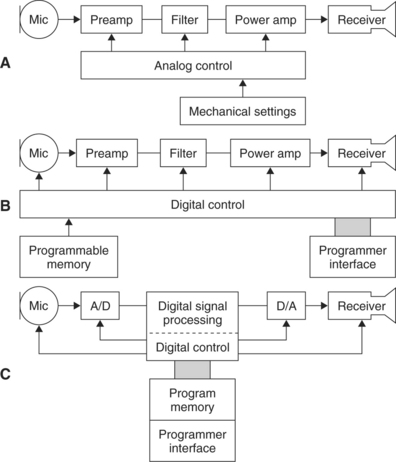
Figure 9-4 Three approaches to the electronic design of hearing aids. A, An analog hearing aid. B, A digitally controlled analog hearing aid. C, A digital signal processing hearing aid. (Modified from Stach BA: Clinical audiology, San Diego, 1998, Singular Publishing Group.)
The information processor (see Figure 2-5, B) in a hearing aid is the amplifier. It performs several functions. The first and most basic of these is amplification of the input signal with a frequency response (amplifier gain between the input and output, which is different at different frequencies) that is matched to speech signals. Amplifiers may be linear or nonlinear (sometimes called curvilinear) (Stach, 1998). Linear amplifiers increase the gain in signal from input to output by the same amount for all intensities of input. This means that a small speech signal and a large noise signal are both amplified the same amount. Linear amplifiers restrict the output to a level that is not harmful to the ear by clipping the signals that are large enough to cause damage. This approach is called peak clipping (see below). In a nonlinear or curvilinear amplifier, the output signal does not have the same proportional relationship to the input as in a linear amplifier. The nonlinear approach provides for compensation for louder signals and greater amplification of speech signals through a variety of approaches. Nonlinear amplification is also more versatile in the processing options it allows. Second, the information processor limits loud input signals to prevent distortion and protect the user from damage to the peripheral auditory system. Finally, signal processing is provided to minimize noise and maximize the speech signal.
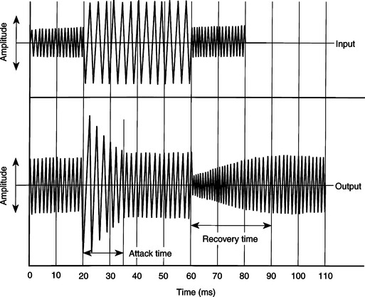
Figure 9-5 The compensation response of a hearing aid to sudden changes in input (top waveform); sound intensity is shown in the bottom trace. (Data from Staab WJ: Hearing aid handbook, Blue Ridge Summit, PA, 1978, TAB Books.)
In an ideal amplifier, all signals are amplified in such a way as to preserve the shape of the input curve at the output of the device. Because the input shape (SPL versus gain plot) is determined by the speech signals picked up by the microphone, maintenance of this shape is important to the signal’s intelligibility. Any difference in the shape of the input and output signals is called distortion. Distortion can arise from several factors and can appear in several ways (Stach, 1998). Two of the most important types of distortion are frequency distortion and noise distortion. Frequency distortion results when certain frequencies are amplified more than others and when there are shifts in the relationship between different frequency bands in the input and output signals. Noise distortion is the result of nonspeech signals being introduced into the amplified output of the hearing aid, which results in decreased intelligibility. Noise may originate within the components of the hearing aid or outside the aid. Examples of external distortion are skin or other materials rubbing against the microphone. Obviously, the lower this noise level, the greater the fidelity and intelligibility of the output speech signal.
With the increase in capability and decrease in size of digital signal processing (including miniaturized computers), there have been significant advances in hearing aid design. The major advantage of using this type of signal processing is that it can be more exactly matched to the acoustic properties of the auditory system than can the less-sophisticated analog signal processing approach of Figure 9-4, A. Preves (1988) describes several of the digital signal processing approaches used in hearing aids (Figure 9-4, B and C). Among the advantages are lower distortion, less acoustical feedback, more precise compression of loud signals, and greater fidelity and intelligibility in the speech signal supplied to the ear.
As stated earlier, the maximal allowable acoustic input at the ear is 130 to 140 dB. One way of limiting this signal is to set a maximal value for the output and cut off any signals that exceed this value. This is referred to as peak clipping. The net result is that loud signals have the peaks of the waveform cut off, or “clipped.” Peak clipping often results in distortion and a decrease in intelligibility of the speech signal (Dillon, 1988). To reduce the negative effects of peak clipping, a concept known as automatic gain control is used in analog hearing aids to automatically decrease the amplifier gain whenever a loud signal is provided at the input. Figure 9-5 shows how this type of compression works. As the input signal is increased in amplitude, the amplifier senses this and reduces the gain. The amount of time that it takes for the amplifier to respond is referred to as the attack time of the circuit. When the input signal is reduced, the amplifier again responds as shown in Figure 9-5. The time it takes the amplifier to recover and increase its gain back to normal is called the response time. These two times are often part of a hearing aid specification. This type of hearing aid compression does not decrease intelligibility of the speech signal for large acoustic inputs (Dillon, 1988).
Nonlinear circuits allow more complex compression methods to be used (Stach, 1998). Nonlinear compression not only limits the effect of loud sounds as described above for analog compression, but it also provides nonlinear gain with various input levels within the user’s dynamic range. Dynamic range is the difference between the softest detectable signal and the loudness of input that causes discomfort. This varies from individual to individual. For individuals who have normal hearing, the dynamic range is up to 100 dB. An individual with significant hearing loss of 50 dB would have a dynamic range of only 50 dB. This might be further reduced if recruitment occurs in the cochlea and auditory nerve, resulting in an increase in the loudness of the signal. Recruitment is common in sensorineural hearing loss (see Chapter 3). One goal of nonlinear speech compression techniques is to fit the input speech into the user’s dynamic range. Low-intensity signals are amplified to be in the user’s range, and high-intensity signals above the user’s comfort range are reduced. Because low- and high-intensity signals require different levels of amplification, a nonlinear approach is needed. This type of nonlinear processing is called dynamic range compression (Stach, 1998). Compression may be applied at the input or output of the hearing aid circuitry. With input compression, the microphone and preamplifier trigger the compression when a signal above a preset threshold is detected. Alternatively, a high output level may be used to activate the compression. This is termed output compression. It is possible to adjust several of the compression parameters, which makes it easier to match the characteristics of the hearing aid to the needs of the user.
The user display (see Figure 2-5, B) for a hearing aid is the speaker. This component is often referred to as the receiver, and it converts the electrically amplified signal to an acoustical waveform that is coupled to the ear. The small size of these devices severely limits the frequency response of the hearing aid for signals above the range of speech. As mentioned previously, most receivers are air-conduction types, which acoustically couple the speech signal to the ear canal. However, when the middle or outer ear precludes the use of an ear mold (e.g., chronic draining ears, atresia, absence of the pinna), bone conduction receivers may be required.
Types of Hearing Aid Signal Processing.
Current hearing aids use one of the three design approaches shown in Figure 9-4 (Stach, 1998). Figure 9-4, A, illustrates the classical analog approach to hearing aid design. The majority of hearing aids made have been of the analog type. Analog hearing aids operate directly on the acoustical signal detected by the microphone; this signal is continuous. In an analog hearing aid, the time-varying input acoustical signal is amplified and filtered and compression is applied if necessary. The signal is then fed directly to the speaker.
The second type of hearing aid circuitry is referred to as digitally controlled analog or hybrid (Levitt, 1997; Stach, 1998). As shown in Figure 9-4, B, the signal path (amplification, filtering, and compression) is still analog, but the control of these circuits is set by digital parameters. Because the digital parameters control the device and can be stored in memory, this device is very flexible. Digitally controlled analog devices can be customized to meet the needs of the user with the parameters stored in the digital memory. Parameters that can be digitally controlled include gain, frequency response, compression parameters, and electroacoustical parameters. The primary reason for the development of the hybrid type of hearing aid was that early pure digital hearing aids were bulky and consumed larger amounts of power than did corresponding analog aids. The hybrid approach gave increased flexibility without the larger size and greater power requirements.
With the development of low-power, small digital signal processing circuits, digital hearing aids (see Figure 9-4, C) are possible. This type of hearing aid uses stored control parameters like the hybrid type; the signal is converted to digital form and then processed. Even these hearing aids have analog preamplifiers to boost the signal to a level sufficient for analog-to-digital conversion. One of the advantages provided by digital circuitry is the capability of shaping the frequency response of the hearing aid. This provides the possibility of canceling acoustical feedback and increasing the signal-to-noise ratio of the hearing aid (Levitt, 1997). Digital aids also can use adaptive filtering to shape the frequency response on the basis of the spectral characteristics of the incoming signal. Currently available digital hearing aids have the computational capability of a small computer. The major limitation at this time is not signal processing capability but rather our limited understanding of the most effective way to process speech signals for people who have hearing aids (Levitt, 1997). As in many areas of assistive technology application, we are limited by our understanding of the clinical and biological aspects of the problem, not by the available technologies.
Cochlear Implants
If there is damage to the cochlea of the inner ear, an auditory prosthesis can provide some sound perception. The first reported use of electrical stimulation of the inner ear was made by the Italian physicist Alessandro Volta (for whom the volt is named) more than 200 years ago. He inserted wires into his ear and connected them to a 50-volt battery, and he experienced an “auditory sensation” when the voltage was applied. More recently, engineers and physiologists have developed sophisticated aids that accommodate lost cochlear function.
These devices, termed cochlear implants, have the components shown in Figure 9-6 (Feigenbaum, 1987). As long as the eighth cranial nerve is intact, it is possible to provide stimulation by use of implanted electrodes. Cochlear implants have been shown to be of benefit to adults and young persons who have adventitious hearing loss (i.e., hearing loss after acquiring speech and language) (Stach, 1998). Significant benefits have also been reported for cochlear implants in young prelingual children (Balkany et al, 2002; Waltzman et al, 2002). Children as young as 18 months old are developing speech largely through auditory input. In recent years, younger and younger children have received cochlear implants to take advantage of their neural plasticity (Ramsden, 2002). There are two major parts of most cochlear implants (Ramsden, 2002). External to the body are a microphone (environmental interface), electronic processing circuits that extract key parameters from the speech signal, and a transmitter that couples the information to the skull. The implanted portion consists of an electrode array (1 to 22 electrodes), a receiver that couples the external data and power to the skull, and electronic circuits that provide proper synchronization and stimulation parameters for the electrode array. Ten-year failure rates are reported to be less than 3% for the internal and external elements combined (Ramsden, 2002).
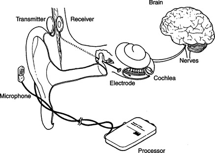
Figure 9-6 The components of a cochlear implnt. (From Radcliffe D: How cochlear implants work, Hearing J November:53, 1984.)
Candidates for cochlear implants must meet certain audiological and age criteria. Severe or profound (>90 dB) bilateral pure tone hearing loss, sentence recognition scores of less than 30%, and age 2 years or more with >90 dB loss in children are the primary criteria for cochlea implants (Loizou, 1998). Age at implant for children and duration of deafness for adults are important factors in obtaining success (Ramsden, 2002). Better results occur for children at younger implant ages and for adults who have had shorter periods of deafness.
Surgical procedures consist of insertion of the electrode array into the cochlea and implantation of the internal components and linking antenna for transcranial transmission of data and power. Ramsden (2002) describes the surgical procedures and possible surgical complications. After the implant is inserted, a period of 1 month or so is allowed for healing, and then a process of “switch-on and tuning” is carried out. Two thresholds are measured: minimal perception of sound and the level at which the sound just ceases to be comfortable. Then the electrode array is tested and signal processing is applied.
The operation of a four-channel cochlear implant system is shown schematically in Figure 9-7 (Loizou, 1998). Sound received by an external microphone is sent to a speech processor. The processed signal is coupled through the skin by a radio frequency transmitter-receiver pair. The internal signal is then fed to the electrode array implanted in the cochlea. One type of process is also illustrated in Figure 9-7: a bank of filters processes the speech information and then converts it into pulses that are sent to the electrodes. Signal processing is discussed in more detail later in this section. The resulting electrical signals at each point in the system are illustrated at the bottom of Figure 9-7. Current approaches to cochlear implants differ in several important respects. The main distinguishing characteristics, shown in Box 9-1, are discussed in depth by Loizou (1998) and summarized in this section.
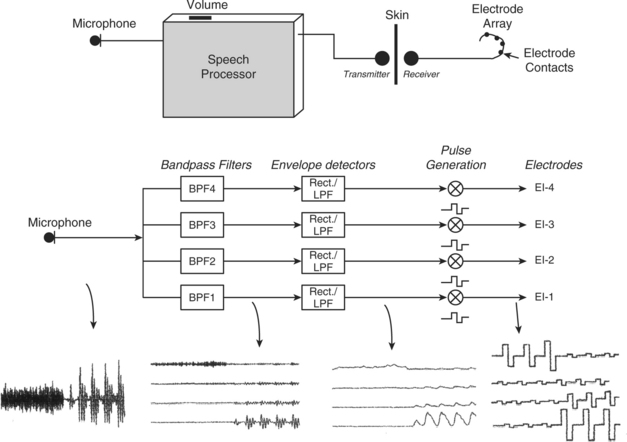
Figure 9-7 Diagram showing the operation of a four-channel cochlear implant. Sound is picked up by a microphone and sent to a speech processor box worn by the patient. The sound is then processed, and electrical stimuli are delivered to the electrodes through a radiofrequency link. Bottom figure shows a simplified implementation of the CIS signal processing strategy using the syllable sa as an input signal. The signal first goes through a set of four bandpass filters that divide the acoustic waveform into four channels. The envelopes of the band-passed waveforms are then detected by rectification and low-pass filtering. Current pulses are generated with amplitudes proportional to the envelopes of each channel and transmitted to the four electrodes through a radiofrequency link. Note that in the actual implementation the envelopes are compressed to fit the patient’s electrical dynamic range. (From Loizou P: Mimicking the human ear, IEEE Signal Process Mag 15:101-130, 1998.)
Electrodes.
The three major considerations in design of electrodes are (1) biocompatibility of materials, (2) placement of electrodes, and (3) the number of electrodes in the array (Shallop and Mecklenberg, 1988). The stimulating portion of most electrodes in current devices is made of platinum-iridium because it is electrically stable and does not react with biological tissue. The “leads,” wires that connect the stimulator to the platinum-tipped electrode, need to be flexible enough to curve around the cochlea, but they also must be rigid enough not to bend as they are inserted. The electrode array and the lead wires are coated with polytetrafluoroethylene (Teflon) or silicone to insulate them from each other and from the tissue. If there are small holes or breaks in the insulation, the tissue near the break will be exposed to electrical current. This can damage both the wire and the tissue. The insulation material must also be impervious to leakage of ionic fluids in the body.
Electrode placement is intracochlear (inside the cochlea), and the size of the electrode is dictated by the microanatomy of the cochlea. The average cochlea is about 32 mm long, and electrode arrays can be up to 25 mm long for insertion into this cavity (usually the scala tympani). Stimulation is either monopolar or bipolar. Monopolar stimulation places one reference electrode outside the cochlea and an array of single electrodes inside the cochlea along the basilar membrane. This arrangement requires less power for stimulation but results in less specific and less focused stimulation in the cochlea. Bipolar stimulation places electrode pairs along the membrane. This results in much more localized and specific stimulation, but it requires more power. Greater power means larger size, and this dictates the type of external packaging. The external package may be in either a BTE or body-level type. The majority of cochlear implants to date have been body-level types. As miniaturized technologies have been enhanced, BTE types have become more prevalent. The minimal spacing between electrode tips, on the basis of electrical stimulation parameters, is 0.5 to 4 mm (Loizou, 1998; White, 1987). This sets a practical limit of 22 electrodes in an array. Several different numbers of electrodes have been used in cochlear implants. Initially all devices used only one electrode. Currently available types of cochlear implants (Clarion, Advanced Bionics Corp., Sylmar, Calif., www.cochlearimplant.com/; Nucleus 24, Cochlear Inc., Lane Cove, Australia, www.cochlear.com/; PUL SARCI, Med El, www.medel.com/) have12, 16, or 22 electrodes (Loizou, 2006).
Transmission of Power and Data.
Because the microphone and speech processing components of cochlear implants need to be adjusted and because of their size and weight, they are placed outside the skull. The electrode array must be inside the cochlea, and there must be a connection through the skull. Initially this was done with wires that passed through the skull and a percutaneous plug that was used when the wires were removed. This type of percutaneous connection is subject to infection, and it has been replaced by a transmitter-receiver approach (Ramsden, 2002). A small induction coil on the external skin surface is connected to the transmitter. This coil transmits through the skin to the receiving coil located directly opposite, under the skin. The receiving coil is connected to the internal electronics and the electrode array. Power for the internal electronics is also coupled through the skin. In some cases the internal circuitry is totally passive and merely passes the stimulation signal to the electrodes. In other cases (such as that shown in Figure 9-6), the internal circuitry processes the incoming signal and distributes it to the different electrodes in the array. This consumes power, which is normally coupled through the skin just as the data are.
Speech Processing.
The purpose of the cochlear implant is to provide an electrically triggered physiological signal that can be related to speech and environmental sounds. The process by which the cochlea, auditory nerve, and higher centers process speech is complex, and it is difficult to design an electronic speech processor that provides physiologically meaningful data to the electrode array.
The area of speech processing or coding of the signals to be sent to the electrode is one in which differences exist among different cochlear implants. Digital processing of the speech signal is aimed at extracting the relevant speech data from the microphone and converting it to a form that provides the most possible information to the user by stimulation of the auditory nerve. To recognize speech, it is necessary to encode frequency, intensity, and temporal patterns (Loizou, 1998, 2006). One approach, shown in Figure 9-7, uses a “vocoder” approach in which the incoming signal is broken down into a set of signals of different frequency through a filter bank. Frequency is encoded in the normal cochlea by location along the basilar membrane (referred to as tonotopic organization). A multiple electrode array can provide different frequencies at different locations along the basilar membrane, but the normal cochlea uses other, more sophisticated methods to further encode frequency (Loizou, 1998). Intensity or amplitude (what we subjectively perceive as loudness) can be encoded by the magnitude of the stimulus at any electrode location. However, the normal cochlea also uses “recruitment” of adjacent hair cells to reflect increased intensity. Recruitment or interaction between the electrode channels can also happen with electrical stimulation of neural tissue as the intensity of the stimulus increases.
Continuous interleaved sampling (CIS) signal processing was developed to avoid some of the problems of channel interactions by delivering temporally offset trains of pulses to each electrode (Loizou, 1998; Wilson et al, 1993). CIS is based on the use of nonsimultaneous interleaved stimulation. In interleaved stimulation, electrodes at different parts of the cochlea are stimulated in sequence rather than those adjacent to each other being stimulated in sequence, and only one electrode is stimulated at one time, helping to eliminate interaction between channels. A key feature is a relatively high rate (greater than 800 pulses per second) of stimulation on each channel, which provides the basis for tracking rapid variations in speech by use of pulse amplitude variations presented to the electrodes. The tradeoff for use of high stimulation rates is more cross-channel interaction. The amplitude of the incoming speech signal must be compressed to avoid damage resulting from overstimulation. As in hearing aids, this process is called compression. Because of the nature of the auditory system, a nonlinear (logarithmic) compression is typically used in cochlear implants (Loizou, 1998, 2006). Intensity of the electrical signal in microamps is analogous to the intensity of the acoustical stimulus in dB. A refinement on the CIS processing approach detects the peaks of the speech signal in several bands. The number of frequency bands is greater than the number of electrodes, and the signals sent to the electrodes are based on the bands with the highest output at any given time. This approach is called ACE (previously called SPEAK) and is implanted on the Nucelus-24 devices (Cochlear Inc., Lane Cove, Australia, www.cochlear.com). Sentence recognition tests with the CIS, SPEAK, and ACE signal processing approaches demonstrated that significantly higher scores were obtained with the ACE than with the SPEAK or CIS strategies (Loizou, 2006). Loizou (1998, 2006) discusses speech processing for cochlear implants in depth and describes current commercial approaches.
Major cochlear implant manufacturers also provide software that is used to program the signal-processing characteristics of the implant to match the needs of the user. These are used after the surgery has been completed and healing has taken place. Signals are supplied to the implant and psychophysical measurements are made to determine the optimal type of signal (pulse or analog) and electrode combinations. This uses pure tone responses. Then speech input is evaluated and adjustments are made to maximize speech intelligibility.
User Evaluation Results.
Almost all postlingually deaf individuals can obtain some degree of open set (the test words or sentences are not known) speech perception without lip reading by use of cochlear implants (Ramsden, 2002). Some users can also communicate over the telephone. The degree of improvement depends on many factors, including the characteristics of the cochlear implant technology used. In general, more channels or electrodes result in greater speech perception (Loizou, 1998). Increasing the number of electrodes or channels will not be effective if there is a smaller number of surviving auditory neurons. The type of signal processing also affects cochlear implant outcomes. For example, the spectral processing method yields greater than 90% correct speech recognition even with a small number of channels, whereas the CIS processing method required up to eight channels to achieve similar results (Loizou, 2006). An area of continued research is aimed at increasing music perception and enjoyment.
In the case of prelingual children, the need for effective auditory perception is critical in the development of spoken language. For deaf children, the cochlear implant has been shown to facilitate development of language at a rate comparable to that of typical hearing children (Balkany et al, 2002). These results are dependent on a number of factors, including age at implantation, length of deafness, and length of use (habituation to the cochlear implant) (Waltzman et al, 2002). Children who receive an implant at an age younger than 5 years perform much better on speech perception tests than do children who are older at the time of implantation. Children who receive an implant before the age of 2 years perform equally well with children who are between 2 and 5 years old when they receive their implant. The minimum age is now 12 months (Balkany et al, 2002). Children who use the cochlear implant full time perform significantly better than those who do not. In general, as the duration of use increases, the performance improves (Balkany et al, 2002; Waltzman et al, 2002). In one study, word recognition scores increased from less than 1% before implantation to 8.9% at 1 year, to 30% at 3 years, and eventually reached 65%, and sentence recognition scores increased from 18% (1 year) to 42% (3 years) to 80% (Waltzman et al, 2002). These average scores were affected by age at implantation (higher scores for those implanted at younger ages).
Waltzman et al (2002) describe the recommended criteria for selecting candidates for implantation and for choosing the ear to be used. Cochlear implants are typically implanted in only one ear. This makes auditory localization more difficult and can result in uneven auditory input. Although there is work on bilateral cochlear implants (Loizou, 2006), the technical problems of stimulation, signal processing, and synchronization are formidable. An alternative approach when there is some residual hearing in one ear is to use a hearing aid in one ear and a cochlear implant in the other (Ching et al, 2001). Clear benefits have been demonstrated from having the combination of hearing aid and cochlear implant, but there are several factors that are important to consider. The use of the cochlear implant may lessen the desire for using the hearing aid because the hearing aid is less attractive or is perceived to interfere with the speech perception from the cochlear implant. If the child is used to the hearing aid, the cochlear implant may not be used as often as is necessary for habituation. Ching et al (2001) present four case studies of children fitted with both a hearing aid and a cochlear implant; they describe success factors and strategies for optimizing effectiveness of this combination of devices.
Telephone Access for Persons Who Are Deaf
The isolation imposed on deaf persons by the telephone is ironic given that Alexander Graham Bell was working on an aid for the deaf when he invented it. For some individuals, additional amplification is sufficient to make the telephone accessible. This may be built into the person’s telephone or it may be an add-on unit that can be placed over the earpiece of any telephone. Both types of devices are available from local telephone companies. As discussed in the previous section, many hearing aids have a magnetic induction feature (telecoil) that allows the output of the telephone to be coupled to the hearing aid electromagnetically.
For many individuals with severe hearing loss, even increased amplification does not make the telephone signal audible. For these persons to obtain access to telephone conversations, a device that can visually send and receive telephone information is used. These individuals also often use master ring indicators, which either amplify the ringing of the telephone or connect the ringer to a table lamp that flashes when the telephone rings. These adaptations are also available from local telephone companies.
Telephone Devices for the Deaf.
Originally, deaf individuals used teletype (TTY) devices designed for sending weather and news information over telephone lines to provide a “visual telephone.” Many of these TTYs were donated by IBM and other companies to help deaf people talk to each other. The original TTY, now obsolete, consisted of a typewriter and electronic circuitry for converting the typed letters to pulses that could be sent over the telephone line to another TTY. The second TTY converted the pulses back into text that was typed on paper on the remote TTY. Because of their low cost, especially for surplus units, TTYs were very popular with deaf individuals, and some are still in use. A good source of information is the Gallaudet University Technology Assessment Program (http://tap.gallaudet.edu).
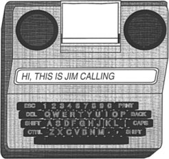
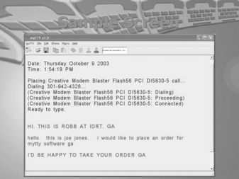
Electronic versions of earlier TTYs are still referred to as TTYs (for example, Ameriphone, by Clarity, Chattanooga, Tenn., http://www.clarityproducts.com/products/categories/category345.asp; Krown Mfg., Inc., Fort Worth, Tex., www.krowntty.com; Ultratec, Inc., Madison, Wis., www.ultratec.com). They use a keypad, a visual display, and a modulator-demodulator (modem) to convert the electronic signal to pulses. Connection to the telephone service is by one of three methods: (1) an acoustical coupler that couples the pulses directly to the telephone handset, (2) direct connection to the telephone line by a cable, and (3) cable connection to a cell phone. Some TTYs also function as telephones with additional amplification for users who are hard of hearing. Several models of current TTYs are lightweight, battery-powered devices for portable use. Some of these units are compatible with cell phones, further increasing access for users who are deaf. Additional features include built-in printers or connections for external printers, automatic answering messages, storage of phone numbers, answering machine capability, storage of conversations, and identification to the person being calling that a TTY is being used. TTYs should be thought of more as a phone than a data modem. An example of a TTY is shown in Figure 9-8. An acoustic coupler is required when calling from a pay telephone. In computer-to-computer telephone line communication, each computer can send and receive at the same time. Thus, if one device is sending, the other unit can interrupt it. This type of operation is called full-duplex. Because of their design, TTYs are only able to send (originate) or to receive at one time, not both; this is called half-duplex mode. After each transmission, the user must type GA (go ahead) to indicate that he is finished and then wait for a response. Half-duplex is also useful when voice communication is occurring because line discontinuities at switching stations or over long distance lines can result in a reflected signal that is heard as an echo by the speaker. Half-duplex switches the direction of transmission based on voice-activated sensors. Full-duplex operation requires that the sending and receiving computers solve the problem of echoes, but it is more rapid and it allows interruption of a long transmission if an error occurs. TTYs are extremely easy to set up and use in the basic configuration. Advanced TTY features include use with an answering machine, remote retrieval of messages, message notification via paging, and a printer. The printer function gives both a permanent record of the conversation and a chance to review messages before responding to them. Some TTYs plug directly into cellular and cordless telephones to allow mobile use.
The TTYs also use a unique coding approach based on five bits of data, rather than the customary eight used in computer ASCII transmission. This code, called Baudot, is widely used by the deaf community, and it is still used in modern TTYs although it does not match the standard for all other computer communication, which is based on the ASCII code. When data are in ASCII form, they can be displayed on a computer screen, enlarged, combined with time or date information, and stored in files for later use. In contrast to ASCII, Baudot does not require a carrier signal, it uses only two frequencies (1800 and 1400 Hz), and it does not require “handshaking” protocols. As discussed in Chapter 7, communication between a computer and a peripheral or another computer is either parallel or serial. In serial transmission a rate of transmission, called the baud setting, must be the same for the receiving and the transmitting devices. TTYs typically use a rate of 110 to 300 baud. Computer modems typically use rates of 2400 baud or higher. The slower TTY speed offers an advantage when single-line displays are used because it is slow enough to be read during the transmission. Three hundred baud is the maximum that can be used easily with an acoustic coupler.
There are two primary ways to use the TTY with the telephone. If both parties have a TTY, then each simply types a message, sends a “go ahead” (the letters GA) command to indicate that he or she is finished, and then waits for an answer. If the deaf person needs to talk to someone who does not have a TTY, then the telephone company provides a relay operator. The operator, who has a TTY, reads the message sent by the deaf person to the hearing person. The response is then spoken to the operator, who types the message to the deaf person’s TTY. Under the provisions of Title IV (telecommunications) of the Americans With Disabilities Act (ADA), all telephone services offered to the general public must include both interstate and intrastate relay services for persons who use TTYs. The Federal Communications Commission (FCC) issued the rules for Title IV, and this agency monitors compliance. These rules also require that both ASCII and Baudot capabilities be provided by the relay services. Approximately 95% of the calls through a relay operator use Baudot data format. Title IV regulations also specify the conduct of relay operators. The most important features of these rules are complete confidentiality and verbatim transmission of messages.
AT&T uses an interesting combination of the technologies described in this chapter in its relay services (Halliday, 1993). A blind operator serves as a relay communications assistant. Incoming voice messages are relayed by typing on a computer terminal that sends the message to the deaf person’s TTY. Incoming TTY messages are converted to braille by use of a refreshable braille display and are then relayed by voice to the hearing person. This is a unique combination of technologies for persons who are deaf and who are blind, and it takes advantage of the skills of each individual.
There are a large number of deaf persons who have and use TTYs (Baudot protocol), and there are also many individuals who have personal computers with modems that use the ASCII protocol. Therefore, current TTYs often include both ASCII and Baudot protocols, and some computer programs that convert from one code to another are available. To use a computer for TTY communication, the user must have both TTY software and a modem that can emulate a TTY (Baudot at 300 baud) (for example, Next TalNXi Communications, Inc., Salt Lake City, Utah; Phone-TTY, Inc., Parsippany, NJ, www.phone-tty.com; Ultratec, Inc., Madison, Wis., www.ultratec.com; Soft TTY (Macintosh only), www.softtty.com/). The TTY software generates the Baudot codes and sends information to the TTY modem (hardware plugged into the computer). The modem then communicates with a stand-alone TTY at 300 baud. The modem must meet all the transmission protocols (e.g., frequency, five-bit code, half-duplex communication) of the Baudot TTY for the communication to be successful. These protocols are not available on standard computer modems, and that is the reason that a special TTY modem (with a setting of 300 baud to communicate in Baudot code with other TTYs) is required for successful communication with a TTY. A typical screen shot of a software-based TTY program in use is shown in Figure 9-9. Several windows are used, including incoming and outgoing messages, a phone book, and a log of past messages.
One of the major advantages of the Baudot-based TTYs is simplicity because all have the same transmission protocol. Use of ASCII offers a variety of protocols that differ in significant ways, and a successful transmission depends on both the transmitting and the receiving parties having the same setup. This requires that the sender know the protocol of the receiver. A hearing person can obtain this information by voice, an option not available to the deaf caller.
Williams, Jensema, and Harkins (1991) compared the features of 11 ASCII-based TTY products to determine their compatibility with Baudot devices. To determine compatibility of ASCII-based TTYs with each other, Williams, Jensema, and Harkins used each of the 11 devices in their sample to call each of the others. This resulted in 110 calls. The purpose of this study was to determine the degree to which deaf people could place a phone call successfully to other TTY products. To parallel the use of Baudot-based TTYs, in which the user can turn on the unit and immediately begin sending and receiving, no adjustment was made in the ASCII protocol other than to set it at the default settings.
Of the 110 outgoing calls, 77 (70%) were unsuccessful (e.g., receiving unit automatically switched to Baudot, garbled, or failed transmission). For incoming calls, 81 (74%) were unsuccessful. Combining incoming and outgoing results, only 12% of the total calls were successful on both ends. Many of the calls resulted in both ends being automatically switched to Baudot, eliminating all the advantages of using ASCII. Also, not all units had automatic switching (three for outgoing, seven for incoming).
Visual Telephones for the Deaf.
Because it requires typing of each utterance, TTY telephone transmission is slow, typically one third to one fourth the rate of human speech (Galuska and Foulds, 1990). Visual sign language, on the other hand, results in communication rates comparable to human speech, and it is the primary form of communication used by individuals who are deaf. It does, of course, require that both the speaker and the listener understand sign language or that an interpreter be available. There are many situations in which this option is unavailable or impractical. For example, in a work setting it is not always practical to have an interpreter available for casual or unscheduled conversations. If standard telephone lines could be used to send visual images of manual signs, it would significantly increase communication rates over those obtained with use of TTYs.
There are several difficulties with sending video information over standard telephone lines. The most significant of these is that video signals contain much more information than audio signals. The way in which this larger amount of information is accommodated is to allow a wider bandwidth for the signals. The bandwidth is a measure of how much information can be accommodated. Because the telephone is intended to serve only voice communication, its bandwidth is very narrow (as low as 3000 Hz). In contrast, television channel bandwidths are measured in megahertz. Thus we have two choices: (1) increase the bandwidth of the telephone or (2) decrease the bandwidth of the video signal. If video telephones come into widespread usage in homes, then the first option will be realized. However, to allow use over any existing telephone line, the second approach is most practical. Narrowing the bandwidth of the video signal is accomplished by data compression (Galuska and Foulds, 1990). In this process the video signal is sent with lower bandwidth, and the intelligibility of the visual signing is used as a criterion for acceptability. Using a test instrument designed to simulate different bandwidths, Harkins, Wolff, and Korres (1991) tested four rates of transmission (slower rates are analogous to lower bandwidths). They found that intelligibility decreased with decreasing bandwidth and that a bandwidth about one third of the normal television signal provided was optimal. Decreases below this level resulted in significantly poorer intelligibility, but bandwidths greater than one third of the normal yielded only marginal improvement. Harkins, Wolff, and Korres (1991) also found that finger spelling at normal rates was less intelligible than whole words at normal rates or reduced-speed finger spelling.
In a work environment there is an alternative to the visual telephone that can provide many of the same benefits: the use of personal computers (PCs) and local area networks (LANs). LANs are typically used to transfer data and messages (e.g., electronic mail) from one PC to another within an office or over a wider network. When PCs and LANs are used in conjunction with a simple video camera and software, visual images can be sent from one computer to another (Galuska, Grove, and Gray, 1992). This allows two individuals with hearing impairments to communicate by sign language. Another, more far-reaching application is to use a LAN to provide interpretive services to a deaf employee or customer. The interpreter can be connected by video on the network to the employee. A speakerphone provides audio connection from the meeting to the interpreter and from the hearing impaired person (by the interpreter) to others at the meeting. The network video provides signed interpretation to the individual with a hearing impairment from the interpreter and from the hearing impaired individual to the interpreter for voice relay to the meeting.
SignWorks (www.deafstudiestrust.demon.co.uk/text/Projects/sworksum) is a project of the Deaf Studies Trust at the University of Bristol in the United Kingdom. The goal is to support deaf business within the United Kingdom. Because there is very little business activity in the United Kingdom by people who are deaf, SignWorks also helps new businesses get started and works with deaf entrepreneurs, managers, and professionals. A key element in this project is the use of multimedia information services. SignWorks uses on-line information services and visual telecommunications to create a system of advice for deaf people in business. SignWorks provides a range of services (e.g., job counseling and training support) and facilitates the development and application of telecommunications equipment. A key element of this project is the use of sign language on the telephone, allowing people who are deaf to conduct daily business on an equal standing with hearing people. The video telephone being used in the project is the mm220 by Motion Media Technology (Bristol, U.K., www.mmtech.co.uk). The videophone will be installed at libraries, schools, support organizations for the deaf, and companies that have deaf employees. The mm220 videophone is about the size of a traditional business telephone. It is one of the first videophones whose picture quality and speed can successfully transmit and receive sign language. It includes a built-in camera, microphone, and video screen. It can also be connected to a PC for two-way data sharing for documents, files, and interaction with Internet-based meetings software.
Another approach is to take advantage of the Internet and to use an interpreter located at a remote location who hears the conversation and then signs it over video for the individual who is deaf (Sorensen Communications, Inc. Salt Lake City, Utah, www.sorenson.com/). This approach is enabled by a broadband videophone appliance specifically designed for deaf and hard-of-hearing individuals (Sorenson VP-100). Sorenson Video Relay Service is a free service to conduct video relay calls with family, friends, and business associates through a certified sign language interpreter, Sorenson videophone, television, and a high-speed Internet connection. The deaf user sees an interpreter on their television and signs to the interpreter, who then contacts the hearing user by a standard phone line and relays the conversation between the two parties.
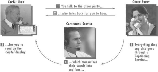
The use of an intermediary relay operator has been extended by one company to include a person who listens to the call as it comes in and captions the auditory information onto a small display built into the telephone (CapTel, Ultratec Madison, Wis., www.captionedtelephone.com/). Figure 9-10 shows how the system works. With this system, the user dials a call as on any other telephone. As the call is dialed, it is also connected to a captioning service. When the call is completed, the other party is connected to the caller in the normal way. In addition, the user captioning service transcribes everything the other party says into written text by use of voice-recognition technology. The written text appears almost simultaneously with the spoken word on a visual display on the captioning phone. The cost of the captioning service is covered by Telecommunications Relay Service funds as part of Title IV of the ADA. This approach requires both a special phone and the availability of the CapTel captioning service as part of the relay service provided by the state. This system also works with external voice answering machine messages.
Voice Over Internet Protocol.
Most telephone calls are made over the public switched telephone network, or PSTN. Increasingly, hearing users are moving to Internet-based telephone service, referred to as voice over Internet protocol (VoIP). There are many advantages to this change, including lower cost, inclusion of multimedia, and the features commonly available with cell phones or land-based networks, such as voicemail, caller ID, three-way calling, and other features included in the basic price of VoIP software or a VoIP service subscription. Originally Internet phone calls stayed within the Internet (PC to PC), but VoIP now bridges to the PSTN.
Although there are many reasons that both hearing and deaf users are attracted to VoIP, there are some issues of accessibility for VoIP (Harkins, 2004). One disadvantage is relay operator service, which is mandated by the PSTN regulator (FCC) under the ADA and into which PSTN companies pay a fee from each user. VoIP companies do not participate in this program and do not typically provide relay service. A second accessibility issue is that VoIP will often garble TTY messages, especially with heavy traffic on the network. TTY messages can also be garbled if lower-quality speech coding is used for the call to save bandwidth. Many TTYs cannot connect to VoIP phones and some VoIP phones cannot connect to any TTY except by acoustical coupling. This reduces access below that of the hearing user. There is technology (NexTalk VM, NXI, www.nxicom.com/products-biz/nextalk_vm.html) that allows Internet protocol (IP)-to-IP text inside an organization’s IP network and allows outside communication with TTYs that are on the public switched telephone network. This is a limited solution relevant only to the organizations that have this technology, not the entire network. Voice quality can also vary over VoIP, which can affect individuals who are hard of hearing. The multimedia aspect of VoIP can lead to more effective use of video and its application to the use of sign language interpreters or lip reading. Advances will undoubtedly be made rapidly in VoIP as it becomes more popular, and this will include TTY compatibility.
Technology for Face-to-Face Communication Between Hearing and Deaf Individuals
The Sorenson method can be effective for face-to face conversations, but it requires time for setup and must be planned in advance for work meetings or casual conversations. For these purposes, assistive technologies that allow communication without speech or sign language interpretation can be very effective. One product, the Interpretype (ITY, Interpretype, Rochester, N.Y., www.interpretype.com/index.php) is designed specifically for this application. This system consists of a preprogrammed laptop-style computer that is able to send typed messages to other ITY units or a computer (Gan, 2005). A built-in display shows the text that is received from the communication partner and displays messages typed into its keyboard. The major advantage of this approach is its simplicity; however, these stand-alone devices are expensive relative to TTYs. For this reason some companies have developed simple modifications to TTYs to allow them to be used a face-to-face communication devices (Modern Deaf Communication, Inc, Danbury, Conn., www.danbury.org/moderndeafcommunication/about_comm_equip.htm) In this case the TTYs are interconnected, rather that being connected to a telephone line. Once connected, they function like the ITY device: one person types and the text show up on the other person’s screen. The primary advantage of using simple technology for face-to-face communication is that it is simple to set up, lightweight to carry, and intuitive to use. Because many deaf individuals have portable TTYs, the modification for face-to-face use is more cost-effective. They still need to buy a second unit, but the total cost for both units can be less than $600 and the total weight can be less than 3 pounds (1.5 kg) (Modern Deaf Communication, Inc).
Alerting Devices for Persons With Auditory Impairments
There are many environmental sounds other than speech about which a person who is deaf needs to know. Examples are telephones, doorbells, smoke alarms, and a child’s cry. There are alerting devices available that detect these sounds and then cause a vibration, a flashing light signal, or both to call attention to the sound. Some devices are very specific. For example, one device is tuned to the frequency of a smoke alarm and it responds only to that sound. When the smoke alarm auditory signal is detected, the visible smoke detector transmits a flasher, which can be connected to a standard lamp. The lamp flashes as long as the smoke detector is active.
Telephone alerting devices include amplified ringers that plug into a standard telephone jack and provide up to 95 dB of ringing sound (McFadden, 1996). Another approach is to use a flashing light that is connected to the telephone line. This can alert the person who is deaf that there is an incoming TTY call. Some systems have a strobe light connected to them; others use a table lamp plugged into the alerting device. The only modification required for these adaptations is a two-plug telephone adapter to allow plugging in of both the adapted alerting device and the telephone.
Doorbells can be both directly wired into a flashing light or detected by a microphone and then converted into a visible (typically a flashing light) or tactile (vibration) signal. For more general sound detection, there are silent alarms that can detect any signal and then transmit to a wrist-worn receiver. This both vibrates and flashes a light to indicate that the sound has occurred. Some devices can accommodate 16 or more channels, and different lights flash for each sound. A microphone and transmitter can be placed in each of the locations where an important sound may occur. For example, one can be near the front door, another near the telephone, another in the baby’s room, and a final one near the back door. When a sound is detected at any of these locations, the wrist unit vibrates and one light is illuminated to indicate which sound has been detected.
Alarm clocks for persons who are deaf generally are either visible (flashing light on a bedside table) or tactile (vibration under the pillow). They may either be built in to an alarm clock (e.g., the entire face of the clock flashes) or they may detect the clock’s alarm and then cause the vibration or flashing light (or both).
One of the major difficulties faced by persons who are deaf is the lack of awareness of sounds associated with traffic. Sirens, horns, and ambient traffic noise all contribute to our ability to drive. Miyazaki and Ishida (1987) developed a device that detects specific sounds and displays a visible alarm to the driver. Traffic horns of different types (air horn on a truck versus a car horn), sirens, railroad crossings, and motorcycles are typical of the sounds detected and displayed.
Assistive Listening Devices
All the devices discussed in this chapter have been designed for use by hearing-impaired individuals. There is also a class of assistive devices that are intended to be used in group settings, such as lecture halls, churches, business meetings, courtrooms, and broadcast television. These are called assistive listening devices.
Small-Group Devices.
For many individuals who have auditory impairments, hearing aids are only effective for one-on-one conversations at close range (and possibly for telephone use). When these individuals are in a group, even a small group of five or fewer persons, it is very difficult for them to understand what is being said; small-group or personal listening devices are helpful in this situation (Williams and Snope, 1985). These devices consist of a microphone and a battery-powered radio transmitter that are worn by the speaker and a receiver that is carried by the person with an auditory impairment. The output of the receiver can either be fed into earphones (personal FM system) or coupled directly to the hearing aid (similar to the telephone aids described earlier). If the person does not normally use a hearing aid or the hearing aids used do not accommodate direct coupling of the signal, the earphones are used. The speaker uses a microphone and whatever he or she says is then transmitted to the listener with a high signal-to-noise ratio. For small-group meetings with several participants, the speaker and microphone can be placed in the middle of the conference table to pick up all the voices. Small-group devices can have multiple receivers for one transmitter if there is more than one person requiring amplification.
Several acoustical parameters affect speech perception in a classroom environment (Crandell and Smaldino, 2000). These are signal-to-noise ratio (SNR), reverberation time (RT), and distance from the speaker.
Classroom noise can be external to the classroom (outside the building such as street noise or inside the building such as other classes, hallway noise, etc.) or inside the classroom (other students talking, heating and air conditioning, moving of furniture). The SNR is the relationship between the speech amplitude from the teacher and the background noise. As the noise level increases, the perception of speech by children with and without hearing impairment falls. The decrement in speech perception is greater for children with sensorineural hearing loss. The greatest effect is on consonant perception. Because noise tends to mask frequencies above it in frequency, the effect is greater with low-frequency noise. Crandell and Smaldino (2000) recommend a SNR of at least +15dB.
RT is the prolongation or persistence of sound as it reflects off hard surfaces, specified as a time delay. Shorter RTs are better for speech perception. RT is longer with lower frequencies because sound is absorbed more readily at high frequencies. Like SNR, RT has a greater effect on children with hearing loss than for typically hearing children. Recommended RT values for classrooms are lower than 0.6 seconds (Crandell and Smaldino, 2000).
The final factor is distance from the speaker. As this distance increases, the sound level decreases up to a critical value determined by the volume of the room, directionality of the speech signal relative to the listener, and the RT. Beyond the critical distance reverberated signals arrive from sources closer than the speaker (e.g., walls, ceiling) and mask the original signal to a greater extent. Positioning a child in the front of the room near the teacher does not solve the problem because reverberated signals and other speech (e.g., a child participating in a discussion) come from throughout the room. These factors indicate that a room that is acoustically well designed (low noise sources, short RT) and have a uniform speaker-to-listener distance will be most effective for children with and without hearing limitations. Classrooms designed within these guidelines have been shown to positively affect academic performance in reading, spelling, concentration, and attention (Crandell and Smaldino, 2000).
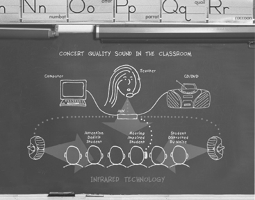
One approach to achieving uniform sound throughout the room and avoiding the problems of distance from the speaker is the use of sound field systems (Ross and Levitt, 2002). As shown in Figure 9-11, the teacher’s voice is transmitted to speakers located around the room, so the teacher’s voice is presented uniformly throughout the classroom. The original systems used FM radio transmission. Recently, infrared (IR) transmission systems have come into use. The primary advantage of the IR systems is that the signal is contained within the classroom and there is no interference between classrooms or from outside radio sources. Research shows that sound from a teacher typically is at a level only about 6 dB above background noise in a typical classroom. Sound field systems can boost this to 8 to 10 dB which is a much more suitable SNR (Ross and Levitt, 2002). The effectiveness of these systems depends on sound acoustical room design to maximize SNR and minimize RT. The maximum benefit of sound field systems is to children with mild hearing loss and those with attention deficit and learning disabilities. For children with more profound hearing loss, sound field systems also allow direct transmission to an individual student through earphones by coupling to a personal FM system. Sound field systems have been shown to increase speech perception, improve academic skills (reading, spelling), and address learning disabilities (e.g., attention). Typically hearing students have also been shown to benefit from sound field systems and teachers benefit from greater student attention and less vocal strain. One additional benefit of some sound field systems is the use of ambient noise compensation (ANC) (Ross and Levitt, 2002). ANC uses digital signal processing to automatically increase amplification if the noise level rises temporarily because of factors such as a transient noise (e.g., air conditioning starting up) or a decrease in the teacher’s speaking volume. Adjustment for these changes in the ANC allows the sound field system to maintain a constant SNR for the student.
Several manufacturers produce devices that combine a conventional BTE hearing aid with an FM system (for example, the Extend Ear, AVR Communication Limited, Eden Prairie, Minn., www.avrsono.com; Microlink, Phonak Staeta, Switzerland, www.phonak.com). Some manufacturers use a “boot” that fits over the bottom of the BTE device and directly couples the amplified sound to the hearing aid. Other manufacturers have built the FM receiver directly into the case of the BTE. In either case, a transmitter sends the radio signal from the person who is speaking to the wireless receiver attached to or built in to the BTE device. The hearing aid user can switch between hearing aid only, hearing aid plus FM, and FM-only modes. In the FM-only mode, the user would hear only the speech of the person wearing the transmitter. However, if the user wanted to monitor his or her own voice or hear another child’s answer to a question in class, the hearing aid plus FM mode might be more appropriate.
Large-Group Devices.
The problems addressed by small-group devices also exist in large meeting rooms such as concert halls, lecture auditoriums, and churches. Under the provisions of the ADA, these areas must be equipped with assistive listening devices. There are several approaches possible, all of which are directly coupled to the public address system of the facility being equipped. These are (1) hard-wired jacks for plugging in earphones, (2) FM transmitter-receiver setups similar to small-group devices, and (3) audio induction loops for transmission to hearing aids equipped with telecoils (Williams and Snope, 1985). Hard-wired systems have the advantage of privacy (there is no transmission over the air) and simplicity of technology. There are two primary limitations of this approach, however. First, rewiring a facility has a high cost and, unless the wiring is done during construction, it is usually not feasible. Second, persons requiring the use of the assisted listening device are forced to sit in a few predetermined locations (where there are earphone jacks).
The audio induction loop devices have their roots in Europe. They require that the user’s hearing aid have an induction coil (telecoil). The major limitations of the induction coil approach are the large amount of power required to drive the induction coil transmitter and susceptibility to interference. FM transmission has a lower level of interference, a large transmission range, and a transmission band specifically for use by persons with hearing impairment (72 to 76 MHz). However, recently the 72- to 76-MHz transmission band has been inundated with interference from cellular telephones, pagers, and other devices. The FCC has put out a notice of proposed rulemaking to secure the band from 215 to 217 MHz for FM system use. FM systems have the advantage that the listener can sit anywhere within range, and they can easily be wired into the normal public address system. Limitations of this approach include varying degrees of strength in the signals being received by the receivers in different hearing aids and a nonuniform transmission pattern resulting in unequal signal strength.
Other assistive listening devices have been developed for television viewing and for use as personal amplifiers (Stach, 1998). Personal amplifiers are hard-wired microphones connected to an amplifier and to earphones worn by the person who is hard of hearing. They are used in hospitals and similar situations for temporary amplification when hearing aids are not available or not worn. Television listeners are assistive listening devices that connect directly to the audio of the television set and transmit the signal to a receiver by FM or ultrasound. The user has earphones connected to the receiver.
Captioning as an Auditory Substitute
Captioning is a process whereby the audio portion of a television program is converted to written words, which appear in a window on the screen. Captioning substitutes visual (text) information for auditory (voice) information. The most common application is in commercial television and films. Captioning is also used as an alternative to sign language interpreters in classrooms, meetings, and for face-to-face conversations.
Closed-Captioned Television and Movies.
When captioning is used in public media (television, movie theaters), it is closed captioning. It is called closed because the words are not visible unless the viewer has a closed-caption decoder. In the United States the Telecommunications Act of 1996 (see Chapter 1) resulted in FCC regulations requiring television broadcasters to provide closed captioning. New programming released after January 1, 1998, must be “fully accessible.” Fully accessible means that 95% of the nonexempt programming must be closed captioned. A telecaption decoder can be connected to a television set, videocassette recorder, or cable television receiver to decode the captioning signal and display the words on the screen. All television sets currently being produced have a built-in closed caption converter. It takes between 20 and 30 hours to close caption a 1-hour television program. The individual broadcasters make decisions regarding which programs are captioned consistent with the regulations described above. Some programs, such as live newscasts, are captioned on the fly, whereas others are captioned in postproduction. With approximately 20 million new televisions sold in the United States each year, every household was expected to have at least one caption-capable set by the year 2000.
More than 3000 titles of home videos and nearly 500 hours of network, cable, and independent programming a week are now available in closed-caption form. Closed captioning includes movies, network news, comedies, sporting events, dramas, and educational, religious, and children’s programming. In excess of 550 national advertisers have closed captioned more than 13,000 commercials. The National Captioning Institute (NCI) can also caption live programs such as news broadcasts, presidential speeches, and coverage of the Olympics. Captions can aid those learning English as a second language and provide assistance in efforts to eradicate illiteracy.
People who are deaf or blind can enjoy first-run movies in theaters. A project carried out by the CPB/WGBH National Center for Accessible Media (www.wgbh.org/wgbh/pages/ncam/) in Boston has developed systems that enable these populations to access movies through closed captions (for deaf patrons) and descriptive narration (for blind patrons). Both these adaptations have been developed to avoid altering of the movie-going experience for the general audience. Reversed captions are displayed by the Rear Window Captioning System on a light-emitting diode text display that is mounted in the rear of a theater. Deaf and hard-of-hearing persons use transparent acrylic panels attached to their seats to reflect the captions so that they appear to be superimposed on the movie screen. The caption users can sit anywhere in the theater because the reflective panels are both portable and adjustable. Blind and visually impaired moviegoers can hear the descriptive narration on headsets using the DVS Theatrical system. The narration is delivered by IR or FM listening systems. These descriptions provide information about key visual elements such as actions, settings, and scene changes. This makes the movies more meaningful to people with vision loss. Initially only available in specialty theaters, these technologies are being introduced into conventional movie theaters. The captioning and descriptive narration systems are integrated into the movie projection sound system by use of CD-ROM technology. A reader attached to the film projector reads a time code printed on the film. The caption and descriptive narration tracks are recorded on a separate CD-ROM, which plays alongside the other disks in the movie sound player. The information on the movie time code signals the CD sound player to play the audio descriptions synchronously with the film soundtrack. The CD player also sends the captions to the light-emitting diode display and the descriptive narration to the IR or FM emitter. WGBH is working with all the major studios and exhibitors to encourage them to adopt these technologies and make closed captions and descriptive narration available for movies on a continuing basis.
Real-Time Captioning for Education and Business Applications.
Computer-assisted realtime (or remote) transcription (CART) has been applied in several different ways (Figure 9-12). For lectures or meetings where there is one deaf participant, CART can be provided one-on-one where a stenographer translates speech into text in real time and it is displayed on a monitor for the individual who is deaf. For meetings in which there is more than one deaf participant, the text output is projected on a screen, generally from a computer. The Internet can also be used to assist deaf individuals with spoken language interpretation. The stenographer has voice connection through the Internet to the meeting or classroom and enters text with a stenotype machine. The text is translated through computer software to text, transmitted over the Internet back to the classroom or meeting, and then read by the deaf individual. Several vendors provide CART services (for example, Hear Ink, www.hearink.com/; Caption First, www.captionfirst.com/).
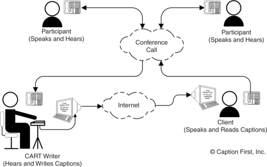
Figure 9-12 Schematic representation of a computer-assisted realtime (or remote) transcription (CART). (Courtesy Caption First, http://www.captionfirst.com/.)
Another example is computer-assisted notetaking (CAN) (Youdelman and Messerly, 1996). A fast typist enters text with a standard computer keyboard and with use of abbreviations (see Chapter 7) to maximize speed of data entry. As in the CART method, text is displayed on a screen. The rate of entry is too slow for the speech to be converted directly to text, so a summary is used. The accuracy of the summary is estimated to be in the 90% to 95% range. In an evaluation study, Youdelman and Messerly (1996) found that notetakers found this approach to be superior to pencil and paper methods because speed could be increased without sacrificing legibility, text could be easily edited, printed copies could be made available to students immediately, and emphasis of important points could be enhanced by bold, italic, or underline formats. The teachers felt that the CAN approach helped students obtain more information than they had with previous methods and that the printed method improved spelling skills. Because CAN was applied to uncaptioned videotapes and other media, it had an additional benefit. The teachers also noted a positive impact on the entire class, not just on the hearing-impaired students, because it helped the entire class focus on the material covered and helped them develop good note-taking skills. The hearing-impaired students stated that CAN helped them understand the material and keep up with the teacher. The children without hearing impairments observed that it was helpful to glance at the display as the teacher was talking to gain information missed orally. They also benefited from the printed notes.
Captioning by Automatic Speech Recognition.
Students who are deaf depend on oral lectures for information in the classroom in elementary, secondary, and postsecondary education, and there is an increase in auditory information on the Web. Given the cost of interpreters ($50 per hour or more) and stenographers for real-time captioning ($100-200 per hour), the cost of making an educational experience accessible for a deaf student is high for universities (Bain et al, 2005). All these factors add to the problems. One possible solution to access to information for people who are deaf is the use of automatic speech recognition (ASR) (see Chapter 7) in captioning systems (Bain et al, 2005). In an ideal system the auditory information would be translated into text and displayed for the deaf user. Current ASR systems are speaker dependent, requiring training of the software to recognize the speech patterns of the speaker. Thus, a general-purpose ASR captioning device that would recognize any speaker’s voice is not currently feasible.
As an intermediary step, IBM in conjunction with a number of universities has developed what they call the Liberated Learning Project (Bain et al, 2005). In this system the ASR system is trained by a professor at the beginning of a course, creating a personalized voice profile. The IBM software, called ViaScribe (www-306.ibm.com/able/solution_offerings/ViaScribe.html), is an ASR application that produces real-time closed-captioning of spontaneous speech. Because the final text is also printed, the system serves as a note-taking application as well. A proof of concept project using VisScribe was conducted in conjunction with St Mary’s University in Nova Scotia, Canada (Bain et al, 2005). This project successfully implanted the basic concept of real-time automatic closed-captioning with significant overall cost savings to the universities involved. ViaScribe allows the instructor to speak naturally without interjecting punctuation (e.g., saying “period” at the end of a sentence), as is required by most ASR systems. When the speaker pauses, the text display skips to the next line. If the ASR makes an error, ViaScribe presents errors written phonetically rather than presenting an incorrect word. The program automatically synchronizes captions with slides or videos. The instructor says commands such as “next slide” or “start presentation” and the captioning appears with the visual information. ViaScribe uses the synchronized multimedia integration language (see Chapter 8) to create a file that synchronizes various media with the text transcript used for captioning. Options include multiple screens or single screens with multiple windows and editing before printing. After a presentation, the multimedia lecture and presentation notes are made available by webcast over the Internet. The Liberated Learning Project evaluation substantiated the promise and feasibility of the concept of ASR to captioning as a viable technology for classroom use in universities (Bain et al, 2005). There needs to be continual improvements in the accuracy and reductions in the time for editing to ensure that this approach is both feasible and cost-effective in the long run.
Basic Principles of Computer Adaptations for Auditory Impairments
The basic characteristics of the graphical user interface are described in Chapter 8. Increasingly, there is auditory information that is included with programs or Web pages. For persons who are deaf, this information may be inaccessible. If an individual is hard of hearing, the system volume can generally be increased. It is also possible to use headphones and link more directly to the user’s auditory system. Computer interaction is bidirectional, and the ATP must understand how computer outputs can be adapted for persons with sensory impairments. Persons who are deaf or hard of hearing also may have difficulties in recognizing auditory computer outputs, such as sounds or speech.
Built-in Options to Increase Usability by Persons Who Are Deaf.
Adaptations that facilitate some of these functions and that are included in the accessibility options in Windows and Macintosh are shown in Table 9-1. ToggleKeys (Windows XP) generates a sound when the CAPS LOCK, NUM LOCK, or SCROLL LOCK keys are pressed. ShowSounds (Windows XP) displays captions for speech and sounds. SoundSentry (Windows XP) generates a visual warning when the system generates a sound. The Flash Screen feature (Mac OS X) provides a visual indication of alert sounds. When a sound is emitted, Flash Screen will also flash the screen once. In addition to the benefit to hearing-impaired students, non-hearing-impaired students my also appreciate the option of having visual rather than auditory alerts. A variety of screen flash options are available. Windows Vista uses Visual Notifications to replace system sounds with visual cues, such as a flash on the screen, so system alerts are announced with visual notifications instead of sounds. The way in which the warning from Sound Notifications is presented is also variable. Vista also allows the user to display text captions for spoken dialog in multimedia programs. By using this option, the user can also cause Windows to display text captions in place of sounds to indicate that an activity is happening (for example, when a document starts or finishes printing).
TABLE 9-1
Simple Adaptations for Auditory Impairment
| Need Addressed | Software Approach |
| User cannot hear speech and sounds produced by programs or Web pages | ShowSounds, Flash Screen, Visual Notifications* |
| User cannot hear sounds used to signal change of operation or error during program operation | SoundSentry |
(www.microsoft.com/enable/); Flash Screen: Macintosh, Apple Computer, Cupertino, Calif. (www.apple.com/education/accessibility/technology/); Visual Notifications: Windows Vista, Microsoft, Redmond, Wash.
Software modifications developed at the Trace Center, University of Wisconsin, Madison. These are included as before-market modifications in most personal computers.
Access to the Internet When Auditory Information Is Difficult for the User.
Because Web pages are a mixture of text, graphics, and sound, they can present challenges to individuals who are deaf or hard of hearing. As the amount of auditory Web content increases, people who are deaf are also prevented from accessing information. Chapter 8 describes general issues of access and how Web pages are developed, including the use of programming languages such as hypertext markup language. The World Wide Web Consortium (W3C) (see Chapter 8) recommendations include accessibility for deaf and hard of hearing users. By using the Microsoft Synchronized Accessible Media Interchange, authors of Web pages and multimedia software can add closed captioning for users who are deaf or hard of hearing. This standard simplifies captioning for developers, educators, and multimedia producers and designers and is available to the public as an open (no licensing fees) standard. This approach is similar to the use of closed captioning for television viewers. The W3C Web Accessibility Initiative synchronized multimedia integration language is designed to facilitate multimedia presentations in which an author can describe the behavior of a multimedia presentation, associate hyperlinks with media objects, and describe the layout of the presentation on a screen. These features allow integration of timing of multimedia presentations into hypertext markup language programs. The W3C Quick Tips shown in Box 8-2 include auditory adaptations.
Aids for Persons With Both Visual and Auditory Impairments
Individuals who are both deaf and blind must use tactile input to obtain information about the environment and to communicate. There are two basic methods used by this group of people. The Tadoma method (described earlier in this chapter) is used to understand speech; finger spelling, with the deaf-blind individual sensing the signs in his hand, is used when both persons in the conversation know signing or one person acts as an interpreter.
Devices for Face-to-Face Communication With Individuals Who Are Deaf and Blind.
A common approach to communication between a nondisabled person and individual who is both deaf and blind is to use a standard keyboard and visual display for the nondisabled person and a braille keyboard and display for the person who deaf/blind (for example, ITY, Intertype, Rochester, N.Y., www.interpretype.com/index.php; FSTTY and FSCommunicator, Freedom Scientific, St Petersburg, Fla., www.freedomscientific.com/fs_products/FlyerPDFs/FSTTYFlyer.pdf; Braille-TTY telephone, Krown, Ft Worth, Tex., www.krownmfg.com/html/products/vtouch_tty.html; Telle-touch, Perkins, Watertown, Mass., https://support.perkins.org/store_product.asp?key={F4F388C9-3A81-4157-A660-841A8B2E2232}; Braillephone, http://www.av-mart.com/Braillephone.htm). This configuration enables direct face-to-face communication with individuals who have no knowledge of sign language or braille to communicate with a person who is both deaf and blind. One approach uses a portable note-taking device (PACMate, Freedom Scientific) with built-in Braille keyboard and refreshable display (see Chapter 8) with PC-based TTY software. An early method (Telle-touch, https://support.perkins.org/store_product.asp?key={F4F388C9-3A81-4157-A660-841A8B2E2232}) uses a regular QWERTY keyboard and a single braille cell. As the hearing user types, the deaf-blind user feels the text one letter at a time. An expansion of that concept has a braille display, TTY, QWERTY keyboard and visible display all built into the same case (Braillephone; Braille-TTY telephone). The TTY function provides the capability for the deaf-blind person to talk to other people who have a TTY or, through a relay operator, anyone with a telephone. The keyboards (braille and QWERTY) and displays (braille and visual) allow face-to face communication. Finally, another approach uses two separate devices connected by cable or wireless transmission (ITY, Intertype). Both the hearing and deaf-blind user have a keyboard and display, which may be QWERTY or braille keyboard and visual or braille display. The advantage of this approach is that the two people communicating can have a more comfortable physical spacing as they communicate because they each have their own devices. The device can either be a stand-alone system designed for this purpose or a computer running special software.
Automated Hand for Finger Spelling.
One of the difficulties for deaf-blind individuals who depend on finger spelling is that the speaker must be able to finger spell or there must be an interpreter present. A further limitation is that the deaf-blind person gives up privacy when an interpreter is used. One approach, still under development, is the use of a mechanical hand connected to a keyboard (Gilden and Jaffe, 1987). The hand is fully articulated; that is, all joints of each finger are independently adjustable. The finger positions for each letter are stored in the computer and are generated when a letter is typed from the keyboard. The mechanical hand can also be connected to a TTY for telephone conversations and to a remote computer by a modem for bulletin boards. Because it is programmed to accept computer input from a keyboard, it can also accept alphabetical characters from a computer. This allows it to be connected to a text-scanning computer in place of the normal voice synthesizer. An evaluation of the second generation of this hand by a group of deaf-blind individuals showed that some could easily interpret the finger patterns, whereas others had great difficulty (Jaffe, Harwin, and Harkins, 1993). On the basis of these results, as well as advances in mechanical design, a third generation of this hand was developed (Jaffe, Harwin, and Harkins, 1993). This version is faster, smaller, and more portable. Finger positions are also more accurately portrayed. Because many deaf-blind individuals are born deaf and blindness develops over the course of the late teenage years, they learn to finger spell early but do not learn braille. Therefore, by the time they become blind they desire a system they can use easily, and the mechanical finger meets this need.
SUMMARY
Hearing aids provide assistance for persons whose hearing is inadequate for conversation. Recent trends in hearing aid design have focused on improved fidelity and digital speech processing. An individual who has damage to the cochlea may benefit from the use of cochlear implants. Emphasis on speech processing algorithms will continue to provide better understanding of how stimulation by cochlear implants can aid speech recognition.
Aids for persons who are deaf use either visual or tactile systems as alternatives. Speech-to-text (sound-to-visual display) devices are not as well developed as text-to-speech aids, and visual information is most commonly used for alarms rather than for communication. Exceptions to this are telephone communication using telephone devices for the deaf (TTYs).
Aids for persons who are both deaf and blind must use tactile substitution. The major approach is braille output with a text-based keyboard for communication between a sighted and a deaf-blind individual. A mechanical device that emulates finger spelling (commonly used by deaf-blind persons) and is driven by a computer with keyboard entry provides communication between a sighted person who does not know finger spelling and a deaf-blind person who does.
1. What are the two basic approaches to auditory sensory aids in terms of the sensory pathway used?
2. List the three basic parts of an auditory sensory aid and describe the function of each part.
3. Discuss the major differences between blindness and deafness in terms of the effect on the individual’s social, work or school, and private lives.
4. What are the major parts of a hearing aid, and what is the function of each?
5. What are the four types of hearing aids?
6. What is acoustic coupling, and how does it affect hearing aid performance?
7. How does a bone-anchored hearing aid function, and when is it used?
8. List the major functions that a cochlear implant must accomplish.
9. What are the major differences among analog, digitally controlled analog, and digital hearing aids?
10. What is meant by compression in hearing aids?
11. What is the difference between linear and curvilinear amplification in hearing aids?
12. How are data and power coupled to cochlear implants?
13. What is the relationship between the number of electrodes and the functional performance for a cochlear implant?
14. What are the major differences between a channel and an electrode in cochlear implants?
15. Describe the major approaches to signal processing used in cochlear implants. What are the advantages and disadvantages of each?
16. What is a TTY, and why is the Baudot code used?
17. What is CapTel and how does it work?
18. Compare a stand-alone TTY with a computer TTY modem using Baudot coding. What advantages does each offer to a deaf user?
19. Why can’t a standard computer modem be used to communicate with a TTY without special software?
20. What are the major limitations to the use of standard telephone lines for visual information transmission (such as for manual signing)?
21. What is computer-assisted realtime transmission and how does it apply to education, business, and personal use?
22. Explain how ViaScribe makes automatic speech recognition a viable captioning option. What are the constraints on this application?
23. What are “alerting devices”? For what purposes are they normally used?
24. What are FM transmission systems for group listening, and how are they typically used?
25. What are the three major assistive technology approaches used for deaf-blind individuals to obtain communication input? What are the relative advantages of each approach?
26. Discuss the major differences between blindness and deafness in terms of the effect on the individual’s social, work or school, and private lives?
References
Bain, K, et al. Accessibility, transcription, and access everywhere. IBM Syst J. 2005;44:589–603.
Balkany, TJ, et al. Cochlear implants in children—a review. Acta Otolaryngol. 2002;122:356–362.
Berger, KW, Hagberg, EN, Rane, RL. Prescription of hearing aids: rationale, procedures and results. Kent, Ohio: Herald, 1977.
Ching, TYC, et al. Management of children using cochlear implants and hearing aids. Volta Rev. 2001;103:39–57.
Crandell, CC, Smaldino, JJ. Classroom acoustics for children with normal hearing and with hearing impairment. Lang Speech Hearing Serv Schools. 2000;31:362–370.
Dillon, H, Compression in hearing aids. Sandlin, RE, eds. Handbook of hearing aid amplification, vol 1. Boston: Little, Brown, 1988.
Dillon, H. Hearing aids. New York: Thieme, 2001.
Feigenbaum, E. Cochlear implant devices for the profoundly hearing impaired. IEEE Eng Med Biol Mag. 1987;6:10–21.
Galuska, S, Foulds, R. A real-time visual telephone for the deaf. In: Proceedings of the 13th Annual RESNA Conference. Washington, DC: RESNA; 1990:267–268.
Galuska, S, Grove, T, Gray, J. A visual “talk” utility: Using sign language over a local area computer network. In: Proceedings of the 15th Annual RESNA Conference. Washington, DC: RESNA; 1992:134–135.
Gan, K. Interpretype—assistive technology for face-to-face communication, Proceedings of the CSUN Conference. http://www.csun.edu/cod/conf/2005/proceedings/2168.htm. [Accessed April 2007.].
Gilden, D, Jaffe, DL. Speaking in hands. SOMA. 1987;October:6–13.
Halliday, J. How can braille help people who are deaf. Hum Awareness Newsl. 1993. [Autumn,].
Harkins, J, Voice over, IP. Some accessibility issues. In: The Blue Book: 2005 TDI national directory and resource guide. Silver Spring, Md: TDI; 2004:21–23.
Harkins, JE, Wolff, AB, Korres, E. Intelligibility experiments with a feature extraction system designed to simulate a low-bandwidth video telephone for deaf people. In: Proceedings of the 14th Annual RESNA Conference. Washington, DC: RESNA; 1991:38–40.
Jaffe, DL, Harwin, WS, Harkins, JE. The development of a third generation finger spelling aid. In: Proceedings of the 16th Annual RESNA Conference. Washington, DC: RESNA; 1993:161–163.
Levitt, H. Digital hearing aids: Past, present and future. In: Practical hearing aid selection and fitting. Washington, DC: Department of Veterans Affairs; 1997:xi–xxiii.
Lieberman, P. Intonation, perception and language. Cambridge, Mass: MIT Press, 1967.
Loizou, P. Mimicking the human ear. IEEE Signal Processing Mag. 1998;15:101–130.
Loizou, P. Speech processing in vocoder-centric cochlear implants. Adv Otorhinolaryngol. 2006;64:109–143.
McFadden, GM. Aids for hearing impairments and deafness. In: Galvin JC, Scherer MJ, eds. Evaluating, selecting and using appropriate assistive technology. Rockville, MD: Aspen Publishers, 1996.
Miyazaki, S, Ishida, A. Traffic-alarm sound monitor for aurally handicapped drivers. Med Biol Eng Comput. 1987;25:68–74.
Olsen, W. Average speech levels and spectra in various speaking/listening conditions: a summary of the Pearson, Bennett and Fidell (1977) report. Am J Audiol. 1988;7:21–25.
Preves, DA, Principles of signal processing. Sandlin, RE, eds. Handbook of hearing aid amplification, vol 1. Boston: Little, Brown, 1988.
Ramsden, RT. Cochlear implants and brain stem implants. Br Med Bull. 2002;63:183–193.
Ross, M, Levitt, H. Classroom sound-field systems. Volta Voices. 2002;9-2:7–8.
Shallop, JK, Mecklenberg, DJ, Technical aspects of cochlear implants. Sandlin, RE, eds. Handbook of hearing aid amplification, vol 1. Boston: Little, Brown, 1988.
Snik, AFM, et al. Consensus statements on the BAHA system: where do we stand at present? Ann Otol Rhinol Laryngol. 2005;114(Suppl 195):1–12.
Stach, BA. Clinical audiology. San Diego: Singular Publishing Group, 1998.
Waltzman, S, et al. Long-term effects of cochlear implants in children. Otolaryngol Head Neck Surg. 2002;126:505–511.
White, RL. System design of a cochlear implant. IEEE Eng Med Biol Mag. 1987;6:10–21.
Williams NS, Jensema CJ, Harkins JE: ASCII-based TDD products: Features and compatibility. In Proceedings of the 14th Annual RESNA Conference, pp 41-43, Washington, DC, 1991, RESNA.
Williams, PS, Snope, T. Assistive listening devices: professional practices. Washington, DC: American Speech-Language and Hearing Association, 1985.
Wilson, BS, et al. Design and evaluation of a continuous interleaved sampling (CIS) processing strategy for multichannel cochlear implants. J Rehabil Res. 1993;30:110–116.
Youdelman, K, Messerly, C. Computer-assisted note taking for mainstreamed hearing-impaired students. Volta Rev. 1996;98:191–200.