Human/Assistive Technology Interface
ELEMENTS OF THE HUMAN/TECHNOLOGY INTERFACE
The Processor: Connecting the Human/Technology Interface to the Activity Output
Keyboard- and Mouse-Emulating Interfaces
Switch-Controlled Computer Keyboard and Mouse Emulation
Communication Devices as Alternative Computer Inputs
CHARACTERISTICS OF CONTROL INTERFACES
Activation and Deactivation Characteristics
Durability and Maintainability
Direct Selection Rate Enhancement
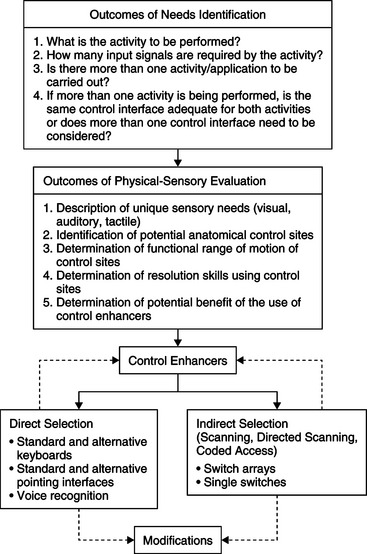
SELECTING CONTROL INTERFACES FOR THE USER
Applying the Outcomes of Needs Identification and Physical-Sensory Evaluations to Control Interface Selection
Control Enhancers: Interface Positioning, Arm Supports, Mouthsticks, Head Pointers, and Hand Pointers
CONTROL INTERFACES FOR DIRECT SELECTION
Built-in Software Adaptations to the Standard Keyboard
Automatic Speech Recognition as an Alternative Keyboard
Touch Screens and Touch Tablets
Access for Users with Cognitive Limitations
Standard and Alternative Electronic Pointing Interfaces
Comparison of Key-Pad and Head-Controlled Mouse Alternatives
Light Pointers and Light Sensors
Modifications to Keyboards and Pointing Interfaces
Keyguards, Shields, and Templates
Technologies for Reducing Accidental Entries
CONTROL INTERFACES FOR INDIRECT SELECTION
Selection Techniques for Scanning
Selection Formats for Scanning
Switch Arrays, Discrete Joysticks, and Chord Keyboards
INTERNET USE BY PERSONS WITH PHYSICAL DISABILITIES
OTHER CONSIDERATIONS IN CONTROL INTERFACE SELECTION
Multiple Versus Integrated Control Interfaces
Mounting the Control Interface for Use
DEVELOPMENT OF MOTOR SKILLS FOR USE OF CONTROL INTERFACES
On completing this chapter, you will be able to do the following:
1 Describe the elements of the human/technology interface and its role within the assistive technology component of the human activity assistive technology model
2 Describe the characteristics of control interfaces
3 Identify and define the basic selection methods
4 Describe the means by which the user’s physical control can be enhanced
5 Discuss a framework for control interface decision making
6 Identify technologies for direct selection
7 Identify technologies for indirect selection
8 Discuss the outcomes that can be achieved through implementation of a motor training program and how technology can be used to improve motor response
9 Describe the computer user interface
10 List the major components of a computer system and give the function of each component
11 Describe the major approaches to keyboard and mouse emulation
12 Describe the major approaches to electronic speech generation used in assistive technologies
The human/technology interface is a major part of the assistive technology component of the human activity assistive technology model. Bailey (1996, p. 173) defines an interface as “the boundary shared by interacting components in a system” in which “the essence of this interaction is communication or the exchange of information back and forth across the boundary.” The human/technology interface is the boundary between the human and the assistive technology across which information is exchanged. This exchange of information is bidirectional and includes both the interface from the person to the device used to control the assistive device and the interface that provides feedback regarding the device’s operation from the device to the person.
The exchange of information in the form of input to operate the device takes place by way of a control interface between the user and the device. It may vary from someone who needs an enlarged light switch to turn a light off and on to someone who needs to access a portable communication system with a single switch to someone who needs to control a power wheelchair with a joystick. The exchange of information from the device to the person takes place through a visual or auditory display. These displays, which have an important role in providing feedback to the user, are also considered a component of the human/technology interface. The role of displays in specific assistive technology applications is discussed in subsequent chapters. Alternative displays for people with visual or auditory impairments are discussed in Chapters 8 and 9, respectively.
In this chapter we discuss the various control interfaces, their characteristics, the control methods that provide the link between the person with a disability and the device being controlled, and the use of electronically generated speech as an output for assistive technologies. A framework for matching control interfaces, control methods, and enhancement techniques to the user’s needs and skills is also presented.
ELEMENTS OF THE HUMAN/TECHNOLOGY INTERFACE
The human/technology interface is more than just a piece of hardware with inputs into the device. There are actually three elements of the human/technology interface that contribute to the operation of a device: the control interface, the selection set, and the selection method. These three elements are interrelated, and careful attention must be given to each element to have an effective human/technology interface.
Control Interface
The control interface (e.g., keyboard, joystick) is the hardware by which the human in the assistive technology system operates or controls a device. It is sometimes also referred to as an input device. The control interface generates from one to an infinite number of independent inputs, or signals, defined as the input domain (Morasso et al, 1979). The input domain may be either discrete or continuous.
A control interface with discrete inputs is one in which each location has a fixed value representing a distinct result with no intermediate steps. For discrete interfaces, the size of the input domain is equal to the total number of targets available to the user. For example, a computer keyboard may have more than 100 keys, each representing a different letter or symbol, which is the signal that is sent to the processor. Although a single switch has only one signal in its input domain, a dual switch has two signals. With a continuous input interface the inputs are continuous, with an infinite number of values. Interfaces that are continuous either vary in quantity along a range, as with a volume control, or maintain an even quantity while providing a continuous input, such as driving straight ahead using a steering wheel to make small adjustments. A proportional joystick and a computer mouse both have a continuous input domain in which there can be an infinite number of possible input signals.
Selection Set
The selection set is the items available from which choices are made (Lee and Thomas, 1990). Selection sets can be represented by traditional orthography (e.g., written letters, words, and sentences), symbols used to represent ideas, computer icons, line drawings or pictures, or synthetic speech. The modalities in which the selection set is presented can be visual (e.g., letters on the keyboard), tactile (e.g., Braille), or auditory (e.g., spoken choices in auditory scanning).
The size, modality, and type of selection set chosen are based on the user’s needs and the desired activity output. Electronic aids to daily living (EADL) or a power wheelchair typically have fewer items in the selection set than an augmentative communication device. The size may also vary according to the user’s skills. For example, an individual who spells and has good physical control has the skills to use the selection set of a standard keyboard, which consists of all the letters and function keys. Another individual who is working on developing language and communication skills may have a selection set consisting of only two picture symbol choices displayed on a lap tray. Selection sets are discussed further in Chapter 11.
Selection Methods
There are two basic methods in which the user makes selections by use of the control interface: direct selection and indirect selection. We refer to these as selection methods. Currently used indirect selection methods include scanning, directed scanning, and coded access.
Direct Selection.
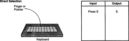
With direct selection the individual is able to use the control interface to randomly choose any of the items in the selection set. The consumer indicates his choice by using voice, finger, hand, eye, or other body movement. In this method of selection the user identifies a target and goes directly to it (Smith, 1991). At any one time, all the elements of the selection set are equally available for selecting; that is, they are not time dependent. Typing on a keyboard or even picking a flower from the garden is considered direct selection. Physically, direct selection requires refined, controlled movements and it is the more difficult of the two methods. Cognitively, there is an immediate, direct result from the selection made; therefore, direct selection is more intuitive and easier to use. Figure 7-1 shows the input that is made by using direct selection to obtain the letter S. The various types of control interfaces that allow the individual to use direct selection are described in the section on selecting a control interface for a user.
Indirect Selection.
With indirect selection, intermediate steps are involved in making a selection. The most common indirect selection method is scanning. With scanning, the selection set is presented on a display and is sequentially scanned by a cursor or light on the device. When the particular element that the individual wishes to select is presented, a signal is generated by the user. With an assistive device, the control interface used for scanning is a single switch or an array of two or more switches. Depending on the needs of the user, scanning can vary in the format used for the selection set and in the manner in which the control interface is used to make the selection. These various techniques are discussed later in this chapter.
Scanning and direct selection require different physical and cognitive skills. Scanning requires good visual tracking skills, a high degree of attention, and the ability to sequence. The advantage of scanning is that it requires very little motor control to make a selection. Ratcliff (1994) measured speed and accuracy in a four-level direction-following task carried out by children in grades 1 through 5 who were using scanning and direct selection. She found that subjects using direct selection made significantly more errors than those using scanning across all grade and difficulty levels. Overall error rates decreased with increasing grade level. Significant differences were also noted between second and third graders and between fourth and fifth graders at the second difficulty level. No other grade or difficulty level differences were statistically significant. Reasons cited for the differences in selection method error rates include the dependence on visual perceptual skills, memory, and the vigilance and attention (necessity to wait for the desired selection) in scanning. Scanning is also more complex cognitively than direct selection because there are additional steps imposed between the user’s action (e.g., hitting a switch or key) and the resulting input. Ratcliff concludes that scanning is a more difficult task than direct selection even for nondisabled children, which has implications for electronic assistive device application.
Because scanning is inherently slow, there have been a number of approaches used to make it more efficient and faster for the user. Some of these involve the location of letters, word completion and prediction, and other text-based approaches. These are discussed in Chapter 11. However, many of these approaches can actually slow down the scanning because they require a larger amount of concentration by the user. An alternative approach is to automatically adjust the scanning rate (reduce the delay between rows, columns, and entries) and maximize the rate for an individual user (Simpson and Koester, 1999). This approach uses a known text passage in which the user enters that passage at as fast a scan rate as possible. If the number of errors increases, the scan delay is increased (rate decreased) by use of a Bayesian probabilistic model. Simpson and Koseter found that, for non-disabled users, the automatic adaptation of scan rate had the potential to increase rate of text entry without the addition of task complexity that occurs in text-based methods.
Directed scanning is a hybrid approach in which the user activates the control interface to select the direction of the scan, vertical or horizontal. Then the device scans the selection set sequentially. When the desired choice is reached, the user sends a signal to the processor to make the selection. This signal is generated either by pausing at the choice, an acceptance time, or by activating another control interface to indicate the choice. In directed scanning, both the type of movement made and the point when the movement is made contribute to the selection (Vanderheiden, 1984). A joystick or an array of switches (two to eight switches) are the control interfaces used with directed scanning. Figure 7-2 gives an example of the input required to select the letter S using directed scanning with a four-position joystick.
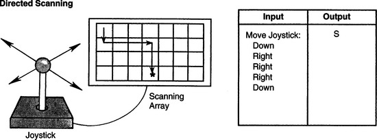
Figure 7-2 Directed scanning showing input required to select the letter S. The user selects the direction of the scan, and the items in the selection set are scanned sequentially by the device. When the desired item is reached, the user makes the selection. (From Smith RO: Technological approaches to performance enhancement. In Christiansen C, Baum C, editors: Occupational therapy: overcoming human performance deficits, Thorofare, NJ, 1991, Slack.)
SlackDirected scanning requires more steps than direct selection but fewer steps than single-switch scanning. The user needs to be able to activate and hold the control interface and to release it at the appropriate time. If the individual can produce the movements required to use this method, the outcome is faster entry of the desired selections into the device.
Another form of indirect selection is coded access. In coded access the individual uses a distinct sequence of movements to input a code for each item in the selection set. Like the other two methods of indirect selection, intermediate steps are required for making a selection. The control interface is a single switch or an array of switches configured to match the code. Morse code is one example of coded access, wherein the selection set is the alphabet but an intermediate step is necessary to obtain a letter. Morse code was developed to be very efficient by assigning the most frequently used letters the shortest codes. This efficiency can be useful in written or conversational communication. In addition, Morse code does not require that a selection set be displayed. The codes are usually memorized, although visual displays, diagrams, or charts can be used to aid in recalling the codes. Morse code and other coded access methods are described in greater detail later in this chapter.
Like scanning, coded access requires less physical skill than direct selection. The advantage of coded access over scanning, however, is that the timing of the input is under the control of the user and is not dependent on the device. The disadvantage is that it takes more cognitive skill, especially memory and sequencing, than direct selection does.
Most current devices can be accessed by more than one type of control interface and selection method. The selection set on most devices can also be varied to match the user’s needs. From a manufacturing perspective, versatility of a device allows it to be applicable to a wider population, which helps to contain the cost of the device and makes it possible to adapt to changing user needs and skills.
The Processor: Connecting the Human/Technology Interface to the Activity Output
When the user activates the control interface, information is sent via a signal to the processor. The processor interprets the information and generates two signals that are converted to (1) feedback to any display that is being used and (2) an activity output, depending on the functions of the assistive technology system. The set of device functions is referred to as the command domain (Morasso et al., 1979). For example, the command domain of a joystick on a power wheelchair is typically configured so that the signal for the UP input is transformed into forward movement of the wheelchair, DOWN into reverse movement, LEFT into movement to the left, and RIGHT into movement to the right. That same joystick can be used to control a television set in which the same input domain of UP, DOWN, LEFT, and RIGHT becomes a command domain of television volume up, volume down, channel up, channel down. In an electric feeder the command domain includes lifting up the spoon, rotating the plate, and putting the spoon back down. In a communication device the command domain is the meaning assigned to each input selection, including functions such as print and speak.
For every element in the command domain there must be a corresponding element in the selection set. The selection set is presented to the user by the selection method. For example, with direct selection each item in the selection set is labeled on the target itself. In direct selection the size of the input domain (number of independent signals) is equal to the size of the command domain. With indirect selection, the input domain has fewer signals than the number of elements in the command domain. With scanning, each item in the selection set is presented sequentially by the device. Thus we can see how the selection method connects the human/technology interface to the command domain of the processor.
Keyboard- and Mouse-Emulating Interfaces.
Many computer adaptations are mandated by the legislation described in Chapter 1 (e.g., Public Law 508). The best approach to adapting a computer for use by individuals with physical limitations is to begin with the simplest modifications designed for the most minimal of physical limitations on the part of the user. We can then progress to more complex adaptations designed to accommodate even the most severely limited potential user. Transparent access is essential for effective access. This term describes two fundamental concepts: (1) 100% of the functions of the computer must be adapted if the user who has a disability is to have full access and (2) all application software that runs on the unmodified computer must also run on the adapted computer. All the keyboard keys, including modifier (e.g., shift, control, alt) and special function keys, and all the mouse functions, such as point, click, and drag, must be available on the adapted input system. If a program (e.g., word processor) works with the standard computer, then it should work with the adaptations. The adaptations also have to be consistent with the operating system of the computer and the hardware configuration (e.g., Windows).
There must be a bridge between the control interface and the computer to use many of the alternatives to keyboard or mouse, such as an expanded keyboard or a single switch, to access a computer. Sometimes this bridge is built into the control interface and other times it is separate. Because the control interface itself is only a switch (or set of switches in a keyboard), pressing a switch or key does not generate any meaningful information for the computer or other assistive device. To make the information meaningful, a decoder must be used (Anson, 1997). In the 1980s and 1990s the Trace Center at the University of Wisconsin developed a standard for general input device–emulating interfaces, or GIDEIs. The GIDEI standard defines the characteristics of a special-purpose processor that translates (i.e., decodes) the signals from the control interface so they match the command domain requirements of the computer. For example, if the computer application requires the use of ESC or DEL keys, then the input device must provide a way for the control interface to generate these key commands. For older devices, the decoding was accomplished through software in the computer, or an additional hardware component (the GIDEI). With the development of the USB standard, particularly the human interface device (HID) component, nearly all of the functions previously developed requiring a special-purpose GIDEI can now be accomplished through the USB interface (Novak and Olsen, 2001). The decoding previously carried out by the GIDEI is built into the control interface (particularly keyboards) and supplied to the computer through the USB port. An additional advantage of the USB port is that it supplies power to the external device from the computer, which eliminates the necessity for an external power source for USB input devices and is especially valuable for assistive technology applications based on portable computers. Additional software may need to be loaded into the computer to allow customization of the control interface selection setup (discussed later in this chapter). There are, however, challenges involved in using the USB HID standard, and these can result in incompatibilities between assistive technology devices and between the device and the host computer (Vanderheiden and Zimmermann, 2002). The existing USB HID standard provides definitions for common human input devices such as keyboards, mouse pointers, joysticks, and game pads. However, it does not currently have a definition specifically for assistive technology input devices. So, assistive technology products must still emulate one of the defined devices (such as a keyboard or mouse) to provide the specialized input. There are no general standards defined to do this for assistive technology developers to follow, which has resulted in different manufacturers using the USB HID in different ways. This has resulted in incompatibilities between assistive technology products and confusion for the end users. The development of an assistive technology definition for the USB HID standard has been proposed to address the issue of incompatibility. There are no general standards for assistive technology applications, and different manufacturers implement the HID standard in different ways. The development of an assistive technology definition for the USB standard has been proposed to address the issue of incompatibility (Marsden, 2005).
Emulating interfaces have a general set of characteristics that allow the computer to be altered for a given application and for a specific person with a disability. Commercial products may be implemented with features that include some or all of these general characteristics, and specific commercial features can change rapidly. The characteristics of an emulating interface are customized through a setup, a concept that originated with the adaptive firmware card (AFC) for the Apple II series of computers (Schwejda and Vanderheiden, 1982). As shown in Box 7-1, a setup consists of three basic elements: (1) an input method, (2) overlays, and (3) a set of options. The features of the setup may be implemented in hardware (electronic circuits) or software (a program) or both. Storage of a setup may be in memory within the emulator hardware or resident in the computer memory. Setups are also usually stored on the computer hard disk drive or in the peripheral device (e.g., an alternative keyboard), which allows them to be loaded into the computer or the emulator as needed. As shown in Box 7-1, the setup is used with an application program.
Several examples of setups that may be used with different application programs are shown in Figure 7-3. The setup shown in Figure 7-3, A, is intended to be used for text entry in a business environment. The application software can be a word processor, a spreadsheet, or a database. The major function is the entry of text characters, and the setup includes several options to make this process more efficient. Autocapitalization automatically enters one space and latches the shift function after sentence-ending punctuation (i.e.,.?!). Abbreviations allow a few characters to be used as a code for a longer word or phrase. The user of the emulator stores both the sequence of characters and their corresponding abbreviation. When the abbreviation (code) is entered, the emulator automatically expands it into the whole stored word or phrase. For example, typing the two letters MN (for “my name”) followed by an abbreviation key would result in the user’s name and address being entered. Several methods of abbreviation expansion and other types of rate enhancement are discussed in Chapter 11. The setup also includes macros, which are codes similar to abbreviations. The macros differ, however, in that they are often used to control application program functions. For example, assume that the word processor requires that the following keys be pressed to set a margin (such as for typing an address on an envelope): SHIFT F8 (shifted function key number 8) 174 ENTER, a total of 6 keystrokes (if SHIFT and F8 are pressed in sequence). A macro for this key sequence could be defined as [ALT]E. This would save four keystrokes (if the ALT key and E were pressed in sequence), and it would also be easier to remember these two keys than the entire key sequence. It is also possible to store mouse functions and “replay” them with one command. Another way to save keystrokes is for the computer to anticipate the words on the basis of previous characters entered. For example, if a T is typed, then an H is very likely to follow. Likewise, it is possible to predict whole words rather than just letters. This method of input acceleration is called word prediction or word completion. In some cases the emulator software program keeps track of the words that the user inputs most frequently, and the choices presented is in the order of frequency of use for the specific person using the emulator. We discuss word prediction further later in this chapter. Many of these options are available for both the Windows (see www.microsoft.com/enable/default.aspx) and Macintosh (see http://www.apple.com/accessibility/) operating systems. Additional information is also available from the manufacturers’ Web sites listed here.
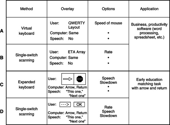
Figure 7-3 A GIDEI setup consists of three parts: input method, overlay, and options. A to D, Four examples of GIDEI setups for different consumers and different applications are shown.
This set of options can be used with any of the input methods shown in Box 7-1. The particular input method determines the overlays. The term on-screen keyboard refers to those keyboard emulation methods that use a video image of the keyboard on the video screen, together with a cursor. An example is shown in Figure 7-3, A. The display of the keyboard layout on the screen can contain key locations for use as macros and it can be arranged to make selections as fast as possible. For a single-switch user, the overlay on the screen may be a scanning array with special characters included, as shown in Figure 7-3, B.
A second setup, shown in Figure 7-3, C and D, is for a young child who is using any of a wide range of software programs that require selection of an answer by matching a cursor (pointer) location with the correct item (Figure 7-4). The task may be to match numbers, letters, shapes, words, or pictures. Often the software requires that one key (e.g., RIGHT ARROW) be used to move the cursor and another key (e.g., RETURN) to select the one that the student believes is correct. Two setups are shown in Figure 7-3 for this application. In this case the user and computer overlays are different, so a speech overlay is also included. Because the user is not likely to have learned to read yet, the speech overlay helps identify the choices to be made. Speech is used as a reinforcer when the choice is made, which is shown as a second speech overlay in Figure 7-3, C. This setup is for use with an expanded keyboard. In this case a visual overlay with symbols can be used. An example is shown in Figure 7-5. Another overlay, Figure 7-3, D, shows the use of scanning on the screen, which is restricted to text characters. For example, an arrow can be generated with two dashes and the greater than () sign. “OK” is used as the label for “this is the one I want” (the student’s choice). Both these setups use the speech, scanning rate, and program slowdown options. However, for the second setup (scanning), an option that allows us to place the scanning array on any line of the display monitor is also included. This option is important because the scan line can hide part of the program if it is in a fixed location.
Figure 7-4 A GIDEI overlay for cursor-controlling movement by using arrows. This is being used with an expanded keyboard and an educational software program.

Figure 7-5 A symbol-based GIDEI overlay for use with an expanded keyboard and an educational software program.
Many USB-based input devices allow other features, such as mouse emulation and the use of macro instructions and multitasking. Mouse emulation substitutes a set of keys, a scanning array, or Morse code characters for mouse functions (similar to MouseKeys, Table 7-1). Macros can be used to return the mouse cursor to a specific location on the basis of stored information. This feature can save time when scanning is the mode used for mouse emulation. All these features can be incorporated into a setup that can be loaded when it is necessary or desirable to use the mouse. Anson (1997) describes the characteristics of several GIDEIs for both Windows and Macintosh operating systems.
TABLE 7-1
Minimal Adaptations to the Standard Keyboard and Mouse*
| Need Addressed | Software Approach |
| Modifier key cannot be used at same time as another key | StickyKeys† |
| User cannot release key before it starts to repeat | FilterKeys† |
| User accidentally hits wrong keys | SlowKeys,† BounceKeys,† FilterKeys† |
| User cannot manipulate mouse | MouseKeys† |
| User wants to use augmentative communication device as input | SerialKeys† in Windows XP or an alternative (like AAC keys) |
| User cannot access keyboard (Windows Vista) | On-screen keyboard (Windows XP and Vista) Built-in ASR |
*Easy Access (part of universal access) in Macintosh operating system, Apple Computer, Cupertino, Calif.; accessibility options in Windows XP, Ease of Access in Windows Vista, Microsoft Corp., Seattle, Wash.
†Software modifications developed at the Trace Center, University of Wisconsin, Madison. These are included as before-market modifications to the Macintosh operating system or Windows in some personal computers and are available as after-market versions in others. The function of each program is as follows:StickyKeys: user can press modifier key, then press second key without holding both down simultaneously.SlowKeys: a delay can be added before the character selected by hitting a key is entered into the computer; this means that the user can release an incorrect key before it is entered.BounceKeys: prevents double characters from being entered if the user bounces on the key when pressing and releasing.FilterKeys: the combination of SlowKeys, BounceKeys, and RepeatKeys in Microsoft Windows.MouseKeys: substitutes arrow keys for mouse movements.SerialKeys: allows any serial input to replace mouse and keyboard; this function has largely been replaced by USB standard devices.
All currently available commercial devices use the USB standard for providing adapted input, and they are designed for either, or both, Windows-based and Macintosh computers. All adapted input devices have a hardware component, and some have software that may be used for operation or customization. All also have provisions for attachment of control interfaces (alternative keyboards, switches, etc.).
Many of the adapted inputs listed in Table 7-2 include keyboard or mouse emulation. Some of these systems may also require a software program to be loaded into the host computer. This software may be used as part of the emulation process, and it also supports specialized setups for the adapted input device to be used with specific software programs (e.g., the educational applications described in Chapter 15).
TABLE 7-2
Alternative Keyboards for Direct Selection
| Category | Description | Device Name/Manufacturer |
| Expanded keyboards | Generally membrane keyboards that have enlarged target areas, often programmable so that key size can be customized; useful for individuals with good range and poor resolution; also useful for individuals with limited cognitive/language skills or visual impairment. | IntelliKeys (IntelliTools); USB King Keyboard (TASH, Inc.); Expanded Keyboard (EKEG Electronics Company, LTD); Big Keys Plus (Inclusive Technologies); Touch and Go and Concept Keyboard (Traxsys Computer Products); Expanded Keyboard (Maltron) |
| Contracted keyboards | Miniature, full-function keyboards, typically with membrane overlay; useful for individuals with limited range of motion and good resolution. | USB Mini Keyboard (TASH, Inc.); Mini Keyboard (EKEG Electronics Co. Ltd.); The Magic Wand Keyboard (In Touch Systems) |
| Touch screens/touch tablets | Activated by either breaking a very thin light beam or by a capacitive array that detects the electrical charge on the finger; the electrode array used to detect where the finger or pointer is touching is transparent; touch screen can be placed over the face of a monitor. | Touch Window (RiverDeep); MagicTouch (Laureate Learning Systems, Inc.) |
| TongueTouch Keypad | Battery-operated, radio frequency–transmitting device with nine pressure-sensitive keys activated by tongue; universal controller processes information sent from keypad to receiver. | UCS 2000 with TongueTouch Keypad (newAbilities, Inc.) |
| Special-purpose keyboards | Keyboards on special-purpose devices, such as augmentative communication and environmental control devices; available keys may be much more limited in number or may be specific in function compared with standard keyboard. | See Chapter 11 |
Data from RiverDeep, San Francisco, Calif. (http://rivapprod2.riverdeep.net/); EKEG Electronics, Vancouver, Canada (http://www.ekegelectronics.com/ ); Laureate Learning Systems, Inc. Winooski, Vt. (www.laureatelearning.com); newAbilities, Inc., Palo Alto, Calif. (www.newabilities.com ); IntelliTools, Petaluma, Calif. (www.intellitools.com); Inclusive Technologies (http://www.inclusive.co.uk/catalogue/index.html); In Touch Systems, Spring Valley, N.Y. (www.magicwandkeyboard.com); Maltron-USA (http://www.maltron-usa.com/expanded.htm); Traxsys Computer Products (http://assistive.traxsys.com/staticProductListing.asp); TASH, Ajax, Ontario, Canada, or Richmond, Va. (www.tashinc.com).
General-Purpose Emulators.
The first general-purpose keyboard emulator to be widely available was the AFC. The original version of this device was intended for use in the Apple II+ computer (Schwejda and Vanderheiden, 1982). The features incorporated in the AFC are still fundamental to most current emulators. In a very real sense, virtually all the basic capabilities have their origins in the AFC. The major advances in emulator design have been the result of advances in the host computer rather than fundamental insights into the process of keyboard and mouse emulation.
Emulators also use built-in synthetic speech feedback in “talking setups” that allow the user to receive auditory and visual prompting and feedback. This feature is useful for young children who may not be able to read, for visually impaired individuals, and as an added input modality for persons with learning disabilities.
The Kenx was originally designed to provide alternative input to the Macintosh computer and was later ported to the Windows operating system as well. It was originally packaged as a combination of hardware and software that incorporated scanning, Morse code, alternative keyboard, and on-screen keyboard functions. The software became known as “Discover.” Today’s software, called DiscoverPro (Madentec, Ltd, Edmonton, Alberta, Canada; www.Madentec.com), works with a number of alternative input devices, including IntelliKeys (IntelliTools, Petaluma, Calif.; www.intellitools.com), IntelliSwitch (Madentec, Ltd), and head pointers such as TrackerPro (Madentec, Ltd), or HeadMouse (Origin Instruments, Grand Prairie, Tex.; www.orin.com). Discover can either be enabled at startup (when the power is turned on) or activated by clicking on the Discover icon once the computer has booted. Some of the most useful features of Discover are those that are specifically aimed at the graphical user interface (GUI). It is possible with Discover, for example, to set tabs on the screen where the mouse is to point and then store the tab as a code (or macro). When the code is entered (by use of any of the basic selection methods and control interfaces), the mouse carries out the movement stored. By saving a series of mouse movements, it is possible to move to a menu, open it, select a specific entry, and then double-click (to start execution), all with one command. This not only saves many mouse movements, but it also avoids errors during tedious and complex movements. If a particular target software application has keyboard-equivalent commands to perform its functions, those can also be issued directly by Discover. Discover also provides row-column scanning with visually enhanced scanning arrays and audible cues, making it useful for people with multiple disabilities (such as blindness and motor impairments). Other useful features include digitized speech, on-screen keyboards, “invisible” setups (for issuing commands without an on-screen keyboard appearing), and development and printing of keyboard overlays for use with expanded keyboards.
The DARCI TOO provides for alternative mouse, alternative keyboard, joystick, and switch input to Windows-based and Macintosh computers. Input to the computer is through the serial port and it conforms to the Trace standard for GIDEI design. Both a hardware component for attaching the external device to the computer and software to accept that input are included. Two versions of the DARCI TOO are available. One uses an external hardware box that connects to a serial port on the computer. Five operating modes are available with the DARCI TOO: scanning, Morse code, DARCI code matrix keyboard, and communication device. The DARCI USB supports Morse code alternative input through the USB port. No additional software is required, but the MouseKeys accessibility feature must be activated for use.
The process by which a computer can be adapted by use of a software program is described by Hortsman, Levine, and Jaros (1989). Programs in this category range from those implementing the basic features of Table 7-1 to the use of alternate control interfaces and selection methods (Gorgens, Bergler, and Gorgens, 1990). The programs described by these authors and others provide access to Windows and/or Macintosh operating systems. Anson (1997) describes these and other approaches.
On-Screen Selection Sets.
On-screen selection sets use mouse (point-and-click) approaches or scanning to make selections. The keyboard image, shown in Figure 7-6, B, is divided into “keys,” each of which is labeled with an alphanumerical character, special character, or function. All the possible keys on the computer keyboard being emulated are included in the on-screen keyboard display. The emulation software places the keyboard or scanning array image on the screen, detects the mouse or scanning cursor position, relates the position to the key label of the on-screen keyboard image, and inserts that character into the keyboard routine of the computer so that it is treated as a typed character. Windows also includes a basic on-screen keyboard in its accessibility options. To enter a character or select a function, the user of the on-screen keyboard positions the cursor inside the desired “key” on the screen. Movement of the cursor can be by mouse, trackball, joystick, switch array, or head-controlled mouse. Once the cursor is located inside the targeted key, the user makes the selection either by activating another switch or by holding the cursor on the choice until the device accepts it. Various types of on-screen keyboards allow changes in the keyboard arrangement, size of the on-screen keys, location of the keyboard on the screen, and methods by which this customization can be accomplished. Many of the on-screen keyboard systems also include other characteristics. One of the most common is a word prediction feature that displays frequently used words as the first few characters are typed. Each word may be in a key location or on a list presented in a window. This type of input acceleration is discussed in more detail in Chapter 11. Other features that can be used to optimize performance include horizontal and vertical cursor movement speed, keyboard layouts, and location of the keyboard image on the screen (e.g., top or bottom, depending on the type of application program that is running). Anson (1997) describes several commercial approaches to both hardware and software for on-screen keyboards.
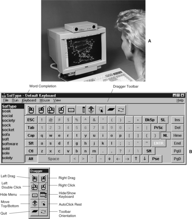
Figure 7-6 A, Head-controlled mouse. B, An example of an on-screen keyboard screen for Microsoft Windows. (Courtesy Origin Instruments Corporation, www.orin.com.)
Shein et al (1991) describe the challenges and the approaches that solve some of the problems in the development of emulators for Windows. They indicate that any visual keyboard in a GUI should have several features. First, selecting keys (e.g., with an on-screen keyboard and head pointer) from the visual keyboard should not transfer the internal computer keyboard routines to the new selection but should keep the computer looking for input from the visual keyboard. Typically, the most recently opened window is “on top” of the others. If the keyboard image is in a window, then it must stay on top even if selections from it open another window. Second, the visual keyboard array should send keystroke input information to the application that is active at any given time. Finally, Shein et al state that the visual keyboard should support a range of layouts. These authors have developed one software-based emulator for the Windows and OS/2 GUIs. Several other commercially available products for Windows are available. These products include a variety of input methods (on-screen keyboard with pointing device, scanning in several modes, Morse code), output options (voice synthesis, enlarged screen characters), and optional features (e.g., word prediction, communication device pop-up windows, environmental control interfaces to telephone and appliances).
The use of more than one switch can enable other functions (Shein et al, 2003). In addition to directed scanning described earlier, these additional functions include a cancel function when an incorrect entry is made, a faster scan to get to a region and then scan slowly through the region, reverse and forward scanning, and similar capabilities. Most on-screen keyboard or scanning arrays allow resizing of keys or selection elements, location of the on-screen display anywhere on the screen, word prediction, and abbreviation expansion.
Switch-Controlled Computer Keyboard and Mouse Emulation.
When scanning is used for computer access, the scanning array resembles an on-screen keyboard, and it may occupy up to half of the screen. The result is that the user has two windows open, one for the scanning array and one for the application program. Additional hardware is required to accept from one to five switches as input. The scanning hardware plugs into the computer through a parallel, a serial, or a USB port. One or more of the scanning approaches described earlier may be used. Once a scanning choice is made, the on-screen keyboard software sends the proper code for the element (alphanumerical or special character) to the computer as if it has been typed. There are several general approaches to single-switch scanning for emulation of mouse functions (Blackstein-Alder et al, 2004). With cartesian scanning, a line moves slowly down the screen when the user presses the scanning switch. As it scrolls down the screen, the line intersects various on-screen icons. If the switch is pressed a second time, a pointer or vertical line moves across the screen. When the pointer or vertical line is located over the desired screen icon, a third switch press selects that icon as though the mouse button had been pressed. This function is similar to matrix-type row-column scanning except that the scan is continuous rather than moving discretely between choices.
A second general approach to scanning mouse emulation is cartesian also, but with discrete scanning between screen elements. This method more closely approximates typical row-column scanning. A third approach is rotational scanning that involves two steps, pointing toward a target and then moving the mouse pointer toward the target. When the user activates the switch once, a scan line is drawn from the center to the right-hand side of the computer screen. This scan line rotates about the center at a continuous speed counterclockwise around the screen. When the line intersects an on-screen target, the user activates the switch a second time to stop the rotational scanning. This line remains visible, and a second perpendicular line begins scanning outward from the center. When this line intersects the desired target, the user hits the switch a third time to make the selection.
Commercial programs also allow the user to select what mouse button function (click to select, double-click to open and run the application, or drag to move) is activated with the third switch press. In some cases the selected function is implemented only after an acceptance time. If an additional switch press occurs before the acceptance time (less than a second, typically), the selection is cancelled, which allows for error correction before an entry is made.
Blackstein-Alder et al (2004) carried out a comparative study of mouse emulation scanning. They used the two types of cartesian scanning, rotational scanning, and a hybrid approach that scans quadrants of the screen and then scans within the quadrant (for example, ScanBuddy, Applied Human Factors, Helotes, Tex.; www.ahf-net.com). Their subjects were all individuals who had a physical disability with cerebral palsy or a related condition. The subjects were given an opportunity to practice with each of the four techniques before using them in a controlled exercise. The length of practice required varied widely among the subjects. Accuracy (number of correct target selected) was variable. About half the subjects had very similar results for all four methods. For the other half, there was more variability among the methods, with the hybrid approach generating the most errors. Three types of errors occurred: hitting too early (before the cursor reached the desired target), hitting too late, and double switch hits in quick succession (perseveration), which cancelled the entry. Selection times for the two cartesian and hybrid approaches were very similar. Selection times for the rotational approach were more than twice as long as for the other three methods. The majority of users favored the discrete cartesian approach. Cartesian continuous was chosen as the favorite by a second group. None chose rotational scanning as the preferred method. Although not directly applicable to clinical applications because of the use of a simplified scanning program for data collection, these results do point out the value of practice and the difficulties in using a rotational approach. Scan times, scanning line width, dwell time before rest or selection, and other characteristics are adjustable on most commercial products.
Another approach to mouse emulation is the creation of on screen “hot spots” in software applications (for example, ClickIT, Intellitools, Petaluma, Calif.; www.intellitools.com/)). These are scanned sequentially. This approach optimizes the scan to only those parts of the GUI screen that are active during an application. The hot spot locations are defined by the user (or more typically a supporter of the user) and stored for a particular application. A variety of approaches (e.g., automatic, inverse, and step) can be used to scan the hot spots with one or two switches. Several commercial products provide for mouse functions during scanning (Dragger, Origin Instruments, Grand Prairie, Tex., www.orin.com; ScanBuddy, Applied Human Factors, Helotes, Tex., www.ahf-net.com). An example is shown in Figure 7-6, A. In general, these programs allow the user to select the mouse function after the selection of a target by using any of the scanning or hot spot approaches described here. A more generic approach is one in which all interface objects in Windows are scanned as hot spots until the scan is stopped by switch activation (WIVIK, WiVik; also http://www.wivik.com/index.html). This action begins the next sequence (e.g., scanning down a list of choices in an opened menu).
The basic operating system allows the speed of mouse movement, the trail left by the mouse, and other features to be adjusted. For individuals with severe motor impairments, the built-in adjustment of mouse speed, cursor size, and so forth are not sufficient to allow use of the mouse or other pointing device. There are commercial products that extend the range of these adjustments and add other features such as wrapping the cursor around the screen when it reaches one side (i.e., when the cursor hits the right edge of the screen it appears again on the left side; for example, PointSmart, Infogrip, Ventura, Calif., www.inforgrip.com).
Single- or dual-switch computer users can also use coded access including Morse code and DARCI (WesTest Engineering, Farmington, Utah; www.westest.com) code. Because codes are typically memory based, they do not require a selection display (a set of characters on the screen), as is needed for an on-screen keyboard or scanning array. This method allows the entire screen to be used for the application software being run. When Samuel Morse invented his code in the late 1880s, there were no computers, and therefore basic Morse code does not include ESC or RETURN keys on the computer or characters such as punctuation or V@#$%. Even more important, Morse saw no need for a SPACE character. He just told his key operators to wait a little longer between dots and dashes (a dot [.] is a short sound and a dash [-] is a longer sound). Unfortunately, the computer requires that a specific ASCII character be sent for SPACE. The absence of standardized codes for anything other than alphanumerical characters (see Figure 7-25) presents a problem with using Morse code for computer access. Examples of codes developed for computer use by several different manufacturers are listed in Table 7-3. Note that in some cases the codes for the same characters are different for the three systems and in other cases they are the same. This variation makes it difficult for the consumer to change from one communication device or adapted input device to another. Once the set of codes is learned and the motor patterns developed, it is very difficult to change to a new set of codes. Computer access with either scanning or Morse code can be accomplished by software programs, hardware adaptations, or combinations of both.
TABLE 7-3
Nonstandardized Morse Codes Used for Computer Access
| Character | Kenx* | Darci Too† |
| ESC | - - -. | ..-.. |
| ENTER | .-.- | .-.- |
| DELETE | ..- -.. | -..-. |
| TAB | -.-..- | -.- -. |
| . | .-.-.- | .-.-.- |
| ! | .-..- | .-..- - |
| $ | .-.-. | -…-. |
| SPACE | ..- - | ..- - |
| , | - -..- - | - -..- - |
| “. | -.- - | - -.- - |
| ( | ..- -. | …- -. |
| ) | ..-.- | -.. - -. |
| UP ARROW | - -.- - | -..--. |
| DOWN ARROW | --..- | |
| LEFT ARROW | - - .. - | ----- |
| RIGHT ARROW | ..-..- | --.-.-. |
| SHIFT | ...-. | ..-.- |
Note: Standard alphanumerical Morse code characters are shown in Figure 7-25.
*Kenx, Madentec, Edmonton, Alberta, Canada.
†Darci Too for Windows-based computers, WesTest Engineering, Bountiful, Utah.
Communication Devices as Alternative Computer Inputs.
Many augmentative communication devices (see Chapter 11) can also function as alternative keyboards for computer access. The communication device is connected to the computer through a serial or USB interface. This connection allows the communication device to send characters to the computer as if they were typed from the computer keyboard. Using the communication device has the advantage that the user has access to the same control interface and selection technique for computer access as he or she uses for communication. This strategy reduces training and skill development time (e.g., no need to learn two keyboard layouts) and allows the user to concentrate on learning how to operate the computer. Another advantage is that any vocabulary (e.g., words or phrases or complete computer commands) stored in the communication device can be sent from the communication device to the computer as a whole by using a serial port. In many currently available communication devices, computer control is a built-in feature. In others it must be added as an option. Accessibility options (Windows) and universal access (Macintosh) provide for input from the communication device with serial keys (see Table 7-1). A standard has been developed to allow all keyboard characters to be sent to the computer, even if the communication device does not have that character. For example, computer keys such as DEL may not be on the communication device, but the user can send a sequence of characters that the computer interprets as the DEL key. Selection of a special-purpose keyboard for a consumer also requires careful consideration of the items presented in Box 7-2.
There are, however, some disadvantages to this approach. One of these is that in many cases the communication device needs to be physically connected to the computer; that is, a cable must be physically plugged in to the computer. An alternative approach is to use wireless links to replace the cable. Most wireless systems use infrared (IR) links, which are similar to the IR environmental control links described in Chapter 14.
A second potential problem is that most communication devices are not able to generate all the possible ASCII codes needed for general-purpose computer access. For this reason, a special standard has been developed for establishing interaction between the computer and the communication device. Table 7-4 lists examples of the character strings used in this standard. All these codes begin with the ESC (escape) code and end with a period (.), and they are intended to be transmitted over a cable to the computer serial port. Unfortunately, not all currently available communication devices support this standard, and it may be necessary for the assistive technology practitioner (ATP) to program the communication device manually to allow use of the computer. For example, one square on a communication device may have the sequence of characters “[ESC]ret.” stored; when this square is selected, the computer responds as though the RETURN key has been pressed. These characters must be programmed into the communication device, together with the other sequences in Table 7-4.
TABLE 7-4
Trace Standard for Computer Input by Augmentative Communication Systems and Other GIDEIs
| Key Designation | ESC Sequence | Computer |
| DEL | [ESC]del. | A |
| DELETE | [ESC]delete. | I, M |
| CONTROL | [ESC]control. | All |
| DOWN ARROW | [ESC]down. | All |
| LEFT ARROW | [ESC]left. | All |
| ENTER | [ESC]enter. | M, I |
| RETURN | [ESC]ret. | A, M |
| TAB | [ESC]tab. | All |
| BACKSPACE | [ESC]backspace. | I, M |
| SHIFT | [ESC]shift. | A, I, M* |
| ALTERNATE | [ESC]alt. | I* |
| CONTROL | [ESC]ctrl. | A, I,* M* |
| ESCAPE | [ESC]esc. | All |
| RESET | [ESC]reset. | A |
| FUNCTION + # | [ESC]f# | I† |
| INSERT | [ESC]insert. | I |
| HOME | [ESC]home. | I |
| END | [ESC]end. | I |
| PAGE UP | [ESC]pageup. | I, M |
| PAGE DOWN | [ESC]pagedown. | I, M |
| KEYPAD | [ESC]keypad. | I, M‡ |
| SCROLL | [ESC]scroll. | I, M |
| PRINT SCREEN | [ESC]print. | I |
| OPTION | [ESC]option. | A, M |
A, Apple II series; M, Apple Macintosh; I, Windows PC.
*Some computers have both left and right shift, control, or alternate keys; use left or right key. For example, LEFT SHIFT = [ESC]lshift., RIGHT ALT = [ESC]ralt., LEFT CONTROL = [ESC]rctrl.
†This sequence is used for each function key, with the key number substituted for the # sign; for example, function key 1 = [ESC]f1.
‡On Macintosh and Windows PCs, the keypad keys are all preceded by kp; for example, 7 on keypad = [ESC]kp7.
According to Table 7-4, to cause a TAB key to be entered, an input device that adheres to the Trace standard looks for the five-character string [ESC]TAB., and when it is received, the program running on the computer reacts as if the TAB key has been pressed by itself from the keyboard. For example, pressing the TAB key in a word processing program moves the cursor five spaces to the right. Another example from Table 7-4 is the entry of a function key. The Trace standard uses the four characters [ESC]F1. as the character string for function key number 1. When this string is sent from the communication device, the computer acts as if the key F1 has been pressed from the keyboard. In many programs, entering this key results in a help menu, and the character string has the same effect as pressing the F1 key.
CHARACTERISTICS OF CONTROL INTERFACES
Before the specific types of control interfaces and the selection of a control interface for the user is discussed, it is necessary to have an understanding of their characteristics. Controls differ according to their spatial, sensory, and activation characteristics (Barker and Cook, 1981). When a control interface is selected for an individual, these characteristics should be taken into consideration. The placement and size of the control interface (spatial characteristics), how it is activated (activation characteristics), and what feedback is obtained as a result of its activation (sensory characteristics) should be considered.
Spatial Characteristics
The spatial characteristics of a control interface are (1) its overall physical size (dimensions), shape, and weight, (2) the number of available targets contained within the control interface, (3) the size of each target, and (4) the spacing between targets. Control interfaces can be grouped into broad categories on the basis of their spatial characteristics. For example, a single switch has one target, and the target size is the dimension (height and width) of the switch. Typically, a single switch can accommodate an individual who has limitations in range and only gross resolution for activation. Switch arrays (including joysticks) have two to five switches, each representing a different target. The user’s range required to access a switch array needs to be larger than for a single switch but still be relatively small, depending on the spacing between the switches. The user’s resolution needs to be more refined than that required for a single switch and less refined than that for a keyboard. A contracted keyboard has keys (targets) of small size in close proximity to each other. Its overall size is also small. The keys on these keyboards range in size from 0.5 to 1.5 cm, and they require relatively fine resolution from the user. The requirement for the user’s range is moderate (less than 15 cm in both horizontal and vertical directions). Standard or commonly used keyboards require moderate range and relatively fine resolution of the user. Finally, expanded keyboards have large overall size and enlarged target size, requiring relatively large range and fine resolution. Switch arrays and keyboards can have from two to more than 100 targets.
Activation and Deactivation Characteristics
Many characteristics are related to the activation of the control interface. The activation characteristics of a control interface consist of the method of activation, effort, displacement, flexibility, and durability and maintainability. Deactivation, or the release, of a control interface is another characteristic that needs to be considered.
Method of Activation.
The method of activation is the way in which a signal sent by the user is detected by the control interface and activates the processor. Table 7-5 shows the methods of activation. The first column identifies the three ways the user can send a signal to the control interface: movement, respiration, and phonation; the middle column shows how each of these signals is detected by the control interface; and the column on the far right provides examples of each type of control interface.
TABLE 7-5
| Signal Sent, User Action (What the Body Does) | Signal Detected | Examples |
| 1. Movement (eye, head, tongue, arms, legs) | 1a. Mechanical control interface: activation by the application of a force | 1a. Joystick, keyboard, tread switch |
| 1b. Electromagnetic control interface: activation by the receipt of electromagnetic energy such as light or radio waves | 1b. Light pointer, light detector, remote radio transmitter | |
| 1c. Electrical control interface: activation by detection of electrical signals from the surface of the body | 1c. EMG, EOG, capacitive, or contact switch | |
| 1d. Proximity control interface: activation by a movement close to the detector but without contact | 1d. Heat-sensitive switches | |
| 2. Respiration (inhalation-expiration) | 2. Pneumatic control interface: activation by detection of respiratory airflow or pressure | 2. Puff and sip |
| 3. Phonation | 3. Sound or voice control interface: activation by the detection of articulated sounds or speech | 3. Sound switch, whistle switch, speech recognition |
Movements by the user can be detected by the control interface in three basic ways. The movement may generate a force, external to the body, that is detected by the control interface. These are mechanical control interfaces, and they represent the largest category of control interfaces. Most switches, keyboard keys, joysticks, and other controls that require movement or force for activation (e.g., mouse, trackball) fall into this category. Force is always required to activate a mechanical control interface; however, mechanical displacement may or may not occur. For example, force-controlled joysticks and membrane keyboards have very little displacement when activated. Electromagnetic control interfaces do not require contact from the user’s body for activation. They detect movement at a distance through either light or radio frequency energy. Examples include head-mounted light sources or detectors and transmitters used with EADLs for remote control (similar to garage door openers). Another example of an electromagnetic control interface is the use of a light beam in a manner similar to the system in many retail stores in which a customer interrupts a light beam when entering or leaving the store. Electrical control interfaces are sensitive to electrical currents generated by the body. One type, called a capacitive switch, detects static electricity on the surface of the body. This is similar to the game children play when they attempt to shock someone with static electricity. A common example of this type of interface is seen in some elevator buttons. The switches require no force, and they are therefore useful to individuals who have muscle weakness. Other electrical control interfaces use electrodes attached to the skin to detect underlying muscle electrical activity. The electromyographic (EMG) signal associated with muscle contraction is the most commonly used signal. Electrodes placed near the eyes can measure eye movements and generate an electro-oculographic (EOG) signal based on eye movements. Proximity control interfaces, the last type of interface that detects movement, are also active at a distance, but they detect heat or other signals without coming into contact with the body. Although infrequently used, body heat sensors have been successful as control interfaces when force cannot be generated. In summary, mechanical and electrical switches both require contact with the body, and mechanical types also require the generation of force. Electromagnetic and proximity switches do not require contact with the body.
The second type of body-generated signal shown in Table 7-5 is respiration. The signal detected is either air flow or air pressure. The use of this type of control interface, generally called a sip-and-puff switch, requires that the user be able to place and maintain the lips around a tube and produce good control of air flow. When sound or speech is produced by the air flow, we call it phonation (see Chapter 3). This is a method of activation that has developed rapidly over the last few years with speech recognition interfaces. Individuals who have physical involvement that makes other means of activating a control interface difficult may be able to produce sounds, letters, or words consistently enough to activate a control interface.
Effort.
The effort required by the user to generate the signal from the control interface is the next activation characteristic to consider. Activation effort varies from zero upward to a relatively large amount. For a mechanical interface, this is the force required to cause switch activation. For an electromagnetic interface, the effort is the minimal distance of movement sufficient to cause activation of the sensors. For example, an individual using a light pointer to choose from an array of different items must have sufficient head movement (the effort) to move the light beam from one element (represented by a sensor) to another element (which has a different sensor) and enough stability to hold the light beam on that element. Electrical interfaces require a range of effort from zero (for a capacitive switch) to relatively high for muscle force activation of an EMG. The EMG is measured by electrodes placed on the surface of the skin. The magnitude of the electrical signal is proportional to the amount of force generated by the muscle (the effort). Depending on the muscle and the sensitivity of the measurement system, the effort can vary from a small force to a large force. The level of effort for proximity switches is the distance of movement required for activation. An example is waving a hand close to a heat-sensitive switch. The activation effort of pneumatic control interfaces is the amount of exhalation or inhalation required for activation, which can be either how hard (pressure) or how fast (flow) air is exhaled or inhaled. For example, some power wheelchair processors use a system in which a hard puff (large effort and high pressure generated) is forward, a soft puff (small effort and low pressure generated) is a right turn, a hard sip is reverse, and a soft sip is a left turn. The difference in these control signals is based primarily on effort generated. Phonation signals also have a level of effort related (at the simplest control interface level) to volume or loudness. Noise-activated or sound-activated switches are similar to those found on some toys. For speech recognition control interfaces, the effort also includes proper pronunciation because the detection is based on identification of a particular word (see the section on speech recognition later in this chapter).
Displacement.
Another characteristic that needs to be considered apart from effort is displacement. Displacement, which is defined as how far a control interface travels from its original position to its activated position, is unique to mechanical control interfaces. Some mechanical interfaces, such as a force-activated joystick, respond to force and require no displacement (Spaeth and Cooper, 1999). In this case the amount of force that the user exerts determines the output of the joystick. If more force is exerted, the output is greater. Because force is detected, rather than amount of travel or displacement of the joystick, the demands placed on the user change. For individuals who can exert a force over a small distance, this type of joystick is ideal. It also provides more tactile feedback to the user. Many mechanical control interfaces require movement and force for activation. The displacement of these control interfaces provides kinesthetic (movement) feedback as well as tactile and proprioceptive feedback (see Chapter 3). This increased amount of sensory feedback is often of benefit to the user. For example, membrane keyboards have very smaller displacement, and the forces to activate them are often smaller than for switches, which have greater displacement. Without the sensory feedback provided by the displacement, however, users frequently press harder than necessary, thinking that more force is needed to activate the keys.
Deactivation.
Although we have focused on the activation of control interfaces, we need to keep in mind that there is also a force required to release, or deactivate, some control interfaces. Muscle contraction is necessary to remove, or release, the body part from the interface. Weiss (1990) measured both activation and deactivation forces for several mechanical interfaces and found that force was required to release the control interface in all cases but that the deactivation force was approximately one third to one half that required for activation.
Flexibility.
The flexibility of the control interface, or the number of ways in which it can be operated by a control site, also needs to be considered. There are many types of keyboards, joysticks, and switches and just as many ways in which the user can activate them. Among individuals with physical disabilities, wide differences in motor performance exist. Depending on the nature of the disability, an individual may or may not have deficits in strength, range of motion, muscle tone, sensation, or coordination. For example, the quality of movement may be smooth or uncoordinated, reflex patterns may dominate movement or be absent, sensory deficits may or may not be present, muscle tone may be normal or increased or decreased, or there may be limitations in range of motion at any joint. Thus one person may push a key with a finger, another may use a thumb, and a third a head pointer. Control interfaces that allow for various ways of activation are considered to be flexible. In general, control interfaces that are activated by movement can typically be activated by several body sites and are considered to be flexible in comparison to control interfaces that are limited to activation by respiration and phonation. Within the category of movement-activated controls, the flexibility varies, for example, from a lever switch, which is most commonly activated by head movement, to a tread switch, which is routinely used for activation by the foot, knee, hand, head, or chin. Some control interfaces, such as the touch switch, have an adjustment for the amount of effort required to activate them. This type of control can be useful for evaluation or for an individual who has fluctuating endurance or a degenerative condition.
The ways in which the control interface can be mounted or positioned for use also contribute to its flexibility. Mounting a control interface at the optimal position in the individual’s workspace facilitates activation. Some control interfaces, such as a computer mouse, are not intended for mounting and need to be used on a table or other flat surface, whereas other control interfaces, such as a joystick, can usually be mounted in a variety of locations and can therefore be activated by the chin, hand, or foot. Mounting systems are discussed later in this chapter.
Durability and Maintainability.
The durability of the control interface is a characteristic that needs consideration as well. Gathering information during the assessment regarding how often the interface is to be used and the amount of force that is to be generated on the interface by the user assists the ATP in making recommendations that correspond to the durability of the control interface. If the control interface is to be used by someone who exerts a great deal of pressure on it because of uncontrolled movements, it must be constructed so it can withstand this type of use. Switches and keyboards made out of plastic, for example, may not hold up well under these circumstances. In the long run it may be cost-effective to buy a more expensive interface made out of metal that will last longer.
A final consideration is the maintainability of the control interface. It is important to consider whether the interface can be easily cleaned and how it should be cleaned so as not to damage any components. Other considerations are whether any of its components need to be replaced periodically and, if so, how difficult a procedure it is. For example, certain switches require a battery to operate, and when the battery dies, it must be replaced. It also helps to know who will be able to repair the control interface if it breaks down and, if it is in need of repair, whether there is a loaner available for the consumer to use in the interim.
Sensory Characteristics
The auditory, somatosensory, and visual feedback produced during the activation of the control interface comprise its sensory characteristics. Some control interfaces provide auditory feedback in the form of a click when activated. For example, keyboards that use mechanical switches for each key usually click when pressed, thus providing auditory feedback. Other keyboards have a smooth membrane surface that does not provide any auditory feedback. Somatosensory feedback is the tactile, kinesthetic, or proprioceptive response sensed on activation of the control interface. For example, the texture or “feel” of the activation surface provides tactile data. The position in space of the control site when the user activates the switch provides proprioceptive data. The data generated as a result of movement provide kinesthetic feedback to the user. When the interface is within the consumer’s visual field, visual data are obtained through observation of the placement and the movement of the control interface. For some individuals the type of visual data will mean the difference between successful and unsuccessful use of a control interface. For example, someone who has difficulty attending to objects in the environment may be more attentive to a switch that is large and bright red or yellow.
There is usually a direct relationship between the sensory data provided by the control interface and the amount of effort required to activate it. A contact switch that is activated by an electrical charge from the body (i.e., requiring only touch) does not provide the user with any somatosensory feedback. There is no force required and therefore little proprioceptive or visual feedback is provided. The contact switch is also silent, so auditory feedback is absent as well. In some instances we can alter the feedback generated by a control interface. For example, adding a beep to a contact switch provides auditory data or placing a distinguishing texture over the surface of a membrane keyboard provides feedback through the tactile system. Other switches, such as the tread, wobble, and rocker, provide abundant feedback in terms of having a certain feel to them (tactile), an observable movement of the mechanism (visual), and an audible click (auditory).
Generally, interfaces that provide rich sensory feedback facilitate performance. On occasion, sensory feedback may be detrimental to the user’s performance. For example, a control interface with an audible click may trigger a startle reflex in the user that interferes with motor movement. The user may eventually adjust to the sound and ignore it, but the ATP may want to consider an alternate control interface. The interrelationship of spatial, sensory, and activation characteristics of control interfaces plays an important role in the design of an assistive technology system. Each of these characteristics must be carefully considered to make effective selections that meet the needs of the consumer.
Rate Enhancement
Rate enhancement refers to all approaches that result in the number of characters generated being greater than the number of selections the individual makes. For example using “ASAP[space]” for “As soon as possible.[space]” saves 16 keystrokes. Because an increased level of efficiency is obtained, the user has to make fewer entries and the overall rate is increased. Rate enhancement goals and approaches differ for direct selection and scanning. In direct selection the goal is to reduce the number of keystrokes while increasing the amount of information selected with each keystroke. In scanning the goal is to optimize the scanning array to reduce the time required to make a desired selection. Specific approaches are discussed later in this section. Rate enhancement is used for many electronic assistive technology applications, including augmentative communication (Chapter 11), computer access (this chapter), cell phone access, and electronic aids to daily living (Chapter 14). Many mainstream software applications use some form of rate enhancement, also called input acceleration. Effective rate enhancement requires that the motor task become automatic (Blackstone, 1990). Motor patterns become more automatic as they are practiced. As the skills improve, motor and cognitive tasks become more automatic and the user becomes an “expert.” As Blackstone points out, once these motor patterns are established, even small changes in the task may result in dramatic decreases in rate.
Direct Selection Rate Enhancement.
Rate enhancement techniques for direct selection fall into two broad categories: (1) encoding techniques and (2) prediction techniques. Vanderheiden and Lloyd (1986) distinguish three basic types of codes: memory based, chart based, and display based. These are compared in Table 7-6. A memory-based technique requires that both the user and his or her partner know the codes by memory or that the user has the codes memorized for entry into the device. Chart-based techniques have an index of the codes and their corresponding vocabulary items. This can be a simple paper list attached to an electronic device or a chart on the wall (e.g., two eye blinks equals “call nurse,” three eye blinks equals “please turn me,” eyes up equals “yes,” eyes down equals “no”). Figure 7-7 illustrates both a chart-based and a display-based approach for Morse code (Vanderheiden and Lloyd, 1986). In each device, two switches are used. The right switch produces dots and the left one produces dashes.
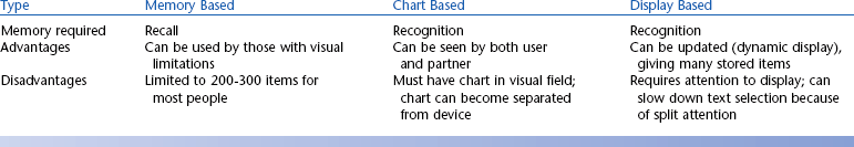
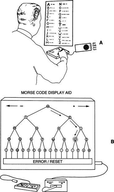
Figure 7-7 Encoding systems may be either (A) chart based or (B) display based. (From Blackstone S:Augmentative communication, Rockville, MD, 1986, American Speech Language Hearing Association.)
American Speech Language Hearing AssociationAbbreviation expansion is a technique in which a shortened form of a word or phrase (the abbreviation) stands for the entire word or phrase (the expansion). The abbreviations are automatically expanded by the device into the desired word or phrase. Beukelman and Yorkston (1984) evaluated five different coding strategies for abbreviations: (1) random number, (2) alphabetical numerical, (3) numerical groupings with alphabetical codes, (4) alphabetical with alphabetical word groupings, and (5) menu-based (similar to number 4, but provides prompting to the user after the category is entered). The third and fourth approaches included both a category (e.g., food) and an item in that category (e.g., banana). These coding strategies were found to be more effective (measured by accurate selections/minute) than either the numerical (worst performance) or alphabetical codes alone. The menu approach yielded midrange performance.
Word prediction or word completion approaches use a window on the screen that displays an ordered list of the most likely words on the basis of the letters entered. In word completion, the user selects the desired word, if any, by entering its code (e.g., a number listed next to the word) or continuing to enter letters if the desired word is not displayed (Figure 7-8) (see Case Study: Word Prediction Vocabularies). Word prediction devices offer a menu of words on the basis of previous words entered. (e.g., “computer” leads to list of “software,” “system,” “program,” “keyboard”). The most important advantage of this approach is the elimination of the need for memorizing codes. Word prediction (or completion) approaches require that the user redirect the gaze from the input (keyboard keys or scanning array) to a list of words after each entry to check for the presence of the desired word, which can reduce the item selection rate compared with letter-by-letter typing. This reduction in selection rate is due to “cognitive or perceptual load” that can offset the benefits achieved in keystroke savings and result in an overall decrease in text generation rate (Hortsman and Levine, 1996).
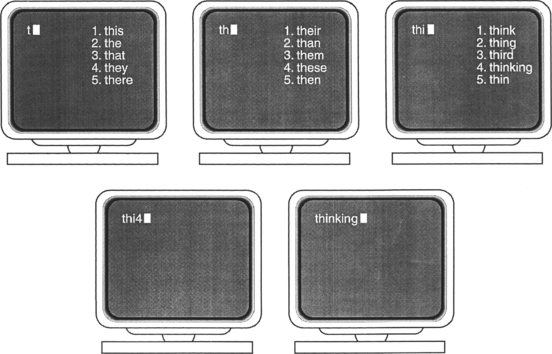
If the word lists are placed on the screen at the point in the document where the typed letters appear, then the user does not need to redirect his gaze to check the word list while typing. This approach can result in significantly fewer switch activations in scanning. One application of this approach, called Smart Lists (Applied Human Factors Helotes, Tex, www.ahf-net.com), can be used with either keyboard or scanning entry. Smart Keys (Applied Human Factors) is similar to the Minspeak icon prediction. After each entry only the keys that contain a prediction on the basis of that entry are left on the on-screen keyboard, which can make scanning significantly faster because only the relevant keys need to be scanned.
Predictive approaches may be fixed or adaptive. Fixed types have a stored word list that is based on frequency of use that never changes. This method is predictable and consistent for the user and can help in the development of motor and cognitive patterns for retrieval. Adaptive vocabularies change the ordering of words in the dictionary list by keeping track of the words used by the person. The words are always listed in frequency-of-use order. This approach is more directly matched to the user’s needs and recent usage.
Current technologies may include combinations of abbreviation expansion and word prediction. Abbreviations are more direct because the user can merely enter the code and immediately get the desired word, and this method allows complete phrases and sentences. Predictions are easier to use because they do not require memorization of codes. These two techniques are actually very similar for fixed predictive systems. For example, in Figure 7-8, the entry for “thinking” is the sequence thi4. This could be entered without having to look at the screen, and it would be equivalent to an abbreviation. These two approaches are compared in Table 7-7.

Scanning Rate Enhancement.
Several rate enhancement approaches are possible in scanning (Lesher, Moulton, and Higginbotham, 1998). Optimization of the row-column matrix is based on placement of the most frequently used characters near the beginning so that they are scanned first. The matrix layout can also be rearranged by using predictive scanning in which word completion or prediction word lists are presented on the basis of previous scanning input. A computer simulation compared switch count (summation of the number of switch hits and the scan times) for seven text samples using each of the 14 techniques relative to a fixed array with the most frequently used characters at the beginning (baseline configuration) (Lesher, Moulton, and Higginbotham, 1998). In a fixed format matrix, placement of symbols (e.g., shift, backspace, and comma) rather than letters is the major factor contributing to switch savings. Changing the matrix with each input using a dynamic matrix rearrangement yielded the greatest average switch savings when the prediction was based on the previous four entries rather than fewer (e.g., two or three) previous entries (Lesher, Moulton, and Higginbotham, 1998). The greatest savings when using word and character lists in the scanning matrix was obtained when the list was presented first and then the matrix was scanned. All these results were based on computer modeling, and issues of motor and cognitive skills for persons who rely on AAC can dramatically affect these results (Horstman and Levine, 1996).
SELECTING CONTROL INTERFACES FOR THE USER
Selecting a control interface for an individual can be a complex process. Understanding the characteristics of control interfaces as described above and following a systematic process to determine the user’s skills and evaluate the effectiveness of control interfaces can make this process easier. Figure 7-9 outlines a framework to guide the ATP through the decision-making process, ultimately leading to the selection of a human/technology interface that matches the user’s needs and skills. On the basis of information acquired from the needs identification and physical-sensory components of the evaluation process described in Chapter 4, the ATP makes a decision to pursue further evaluation on one of two paths: (1) interfaces for direct selection or (2) interfaces for indirect selection. In general, control interfaces for direct selection typically have greater numbers of targets and require more refined resolution skills. Control interfaces for indirect selection have eight or fewer targets and are more suitable for individuals with gross motor control. To make an informed decision regarding the most appropriate control interface for a user, the ATP needs to understand the alternatives that are available and evaluate and compare the consumer’s ability to operate them. The following sections describe specific control interfaces for both direct and indirect selection and factors that influence the selection of one particular interface over another.