Extraoral Imaging
After completion of this chapter, the student will be able to do the following:
• Define the key terms associated with extraoral imaging
• Describe the purpose and uses of extraoral imaging
• Describe the equipment used in extraoral imaging
• Detail the equipment and patient preparations necessary before exposing an extraoral projection
• Identify the specific purpose of each of the extraoral projections
• Describe the head position, the receptor placement, and the beam alignment for each of the following: lateral jaw projection–body of the mandible, lateral jaw projection–ramus of the mandible, lateral cephalometric projection, posteroanterior projection, Waters projection, submentovertex projection, reverse Towne projection, and transcranial projection.
As discussed in Chapter 22, it is not always possible to obtain adequate diagnostic information from a series of intraoral images. Jaw fractures, impacted teeth, and large lesions cannot always be seen well enough on intraoral projections. In such cases, extraoral images can be used to view large areas of teeth and bone. The extraoral image allows the dental professional to view a large area of the jaws and the skull as a single image.
The purpose of this chapter is to present the basic concepts of extraoral imaging and describe the necessary patient and equipment preparations. In addition, this chapter introduces a number of extraoral projection techniques and describes receptor placement, patient positioning, and beam alignment for such projections.
Basic Concepts
As the term extraoral suggests, an extraoral image is one that is placed outside the mouth during x-ray exposure. Extraoral imaging is used to view large areas of the skull or the jaws. Many types of extraoral projections exist and are primarily used in orthodontics and oral surgery. The most common extraoral image is the panoramic projection (see Chapter 22).
Purpose and Use
The extraoral image shows an overall view of the skull and jaws. The extraoral projection is typically used for the following purposes:
• To evaluate large areas of the skull and jaws
• To evaluate growth and development
• To detect diseases, lesions, and conditions of the jaws
In some cases, an extraoral projection is indicated because the patient has swelling or discomfort and is unable to tolerate the placement of intraoral receptors. Extraoral projections may be used alone or in conjunction with intraoral projections. As in the case of panoramic projections, extraoral images are not as defined or sharp as are intraoral projections.
Equipment
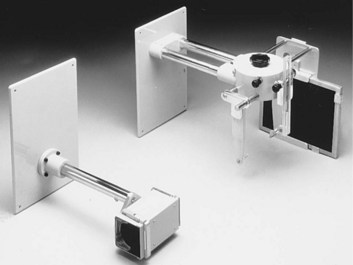
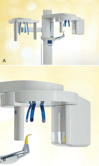
A standard intraoral x-ray machine (see Chapter 6) may be used for a variety of extraoral images (e.g., transcranial and lateral jaw projections). To aid in patient positioning and alignment of the x-ray beam, special head-positioning and beam alignment devices can be added to the intraoral x-ray machine (Figure 23-1). Some panoramic x-ray units (see Chapter 22) may also be used for obtaining extraoral projections. In such cases, the panoramic x-ray tubehead is used in conjunction with a special extension arm and a device known as a cephalostat, or craniostat (Figure 23-2). The cephalostat includes a receptor holder and head positioner, which allow the dental radiographer to position both the receptor and the patient easily.
Film
When a film is used for extraoral exposures, a screen film is placed in a cassette with intensifying screens. The screen film is sensitive to the light emitted from intensifying screens (see Chapter 7). The use of a screen film and intensifying screens minimizes the x-ray exposure necessary to produce a diagnostic image. As discussed in Chapters 7 and 22, some screen films are sensitive to green light (Kodak T-Mat G, T-Mat L, Ortho G, and Ortho L), whereas others are sensitive to blue light (Kodak X-Omat RP and Ektamat G). Blue-sensitive film must be paired with screens that produce blue light, and green-sensitive film must be paired with screens that produce green light. Extraoral film sizes vary; the sizes most often used are 5 × 7 inch and 8 × 10 inch.
An occlusal receptor (size 4) may be used for some extraoral images (e.g., lateral jaw or transcranial projection). The occlusal film is a nonscreen film and does not require the use of screens for exposure. As discussed in Chapter 7, a nonscreen film requires more exposure time than does a screen film. As a result, the occlusal receptor used extraorally requires more radiation exposure than does a screen film. In addition, the occlusal film used extraorally does not cover as large an area as does a screen film.
Intensifying Screens
An intensifying screen is a device that converts x-ray energy into visible light; the light, in turn, exposes the screen film. As discussed in Chapters 7 and 22 , calcium tungstate screens emit blue light, and rare earth screens emit green light. The screen film must be compatible with the light emitted from the screen; blue-sensitive film must be paired with screens that emit blue light, and green-sensitive film must be paired with screens that emit green light. Rare earth screens require less exposure than calcium tungstate screens. To minimize patient exposure, the fastest film and screen combination that provides a diagnostic image should be used.
Cassette
The purpose of the cassette is to hold the receptor in tight contact with the intensifying screen and to protect the receptor from exposure to light (see Chapter 7). Extraoral cassettes, with the exception of some panoramic cassettes, are rigid and are constructed of metal and plastic.
The cassette must be labeled before exposure to orient the finished image; a metallic “R” or “L” can be used to identify the patient’s right or left side. These metallic letters must always be placed on the front of the cassette. The front side of the cassette is typically constructed of plastic and permits the passage of the x-ray beam, whereas the back side is made of metal to reduce scatter radiation. The front side is also known as the “tube side,” or the side that faces the x-ray beam. The front side of the cassette must always face the patient during exposure.
Grid
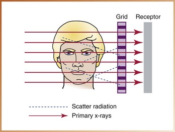
A grid is a device used to reduce the amount of scatter radiation that reaches an extraoral film during exposure. Scatter radiation causes film fog and reduces contrast. A grid can be used to decrease film fog and increase the contrast of the image.
A grid is composed of a series of thin lead strips embedded in a material (e.g., plastic) that permits the passage of the x-ray beam. The grid is placed between the patient’s head and the film. During exposure, the grid permits the passage of the x-ray beam between the lead strips. When some of the x-rays interact with the patient’s tissues, scatter radiation is produced; this scatter radiation is then directed at the grid and the film at an angle. As a result, scatter radiation is absorbed by the lead strips and does not reach the surface of the film to cause film fog (Figure 23-3). To compensate for the lead strips found in the grid, exposure time must be increased. Because of this increase in exposure time, a grid should be used only when improved image quality and high contrast are necessary.
Step-by-Step Procedures
Step-by-step procedures for the exposure of an extraoral projection include equipment preparation, patient preparation, and patient positioning. Before exposing an extraoral projection, infection control procedures (as described in Chapter 15) must be completed. If an extraoral x-ray unit with cephalostat is used, the ear rods must be wiped with a disinfectant between patients.
Equipment Preparation
The dental radiographer must prepare the equipment before preparing a patient for the exposure of an extraoral projection (Procedure 23-1).
Patient Preparation
After preparing the equipment, the dental radiographer must prepare the patient (Procedure 23-2).
Extraoral Projection Techniques
A variety of projection techniques are used in extraoral imaging (Table 23-1). The purpose, receptor placement, head position, beam alignment, and exposure factors differ for each projection used in lateral jaw imaging, skull imaging, and temporomandibular joint imaging.
TABLE 23-1
Extraoral Projection Techniques
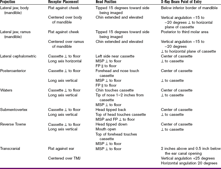
FP, Frankfort plane; MSP, midsagittal plane; TMJ, temporomandibular joint; ⊥, perpendicular;  , parallel.
Lateral Jaw Imaging
Lateral jaw imaging is used to examine the posterior region of the mandible and is valuable for use in children, in patients with limited jaw opening due to a fracture or swelling, and in patients who have difficulty stabilizing or tolerating intraoral receptor placement. Although lateral jaw imaging is useful, it is important to note that because more diagnostic information is obtained from a panoramic image, it is preferred to the lateral jaw image.
As the term lateral jaw imaging indicates, the receptor in this extraoral projection is positioned lateral to the jaw during exposure. Lateral jaw imaging does not require the use of a special x-ray unit; a standard intraoral x-ray machine can be used. The following two techniques are used with lateral jaw projection:
Body of Mandible
Purpose: The purpose of the lateral jaw projection–body of mandible is to evaluate impacted teeth, fractures, and lesions located in the body of the mandible. This projection demonstrates the mandibular premolar and molar regions as well as the inferior border of the mandible (Figure 23-4).
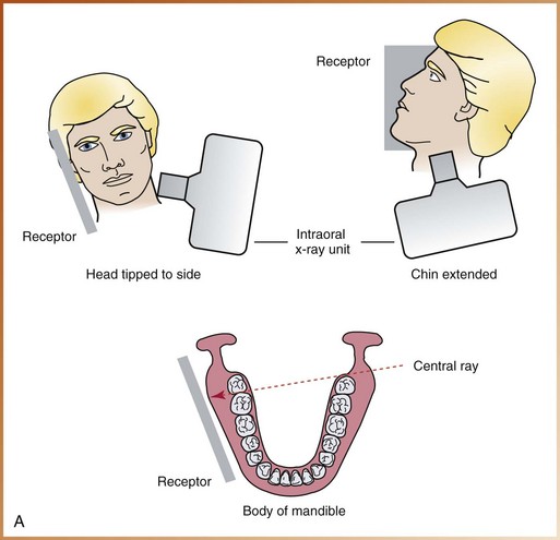
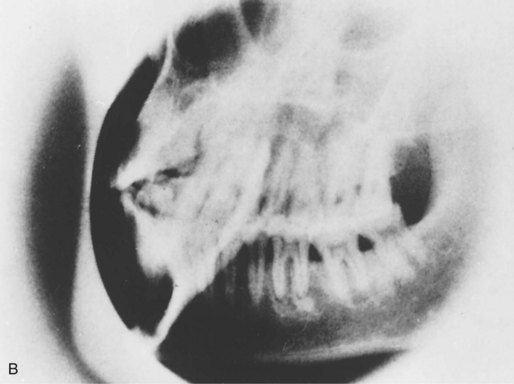
FIGURE 23-4 A, For the lateral jaw projection of the body of the mandible, proper patient positioning and receptor positioning are shown as viewed from the front and side of the patient. B, Example of lateral jaw image–body of mandible. (A and B, Courtesy of Dr. Robert M. Jaynes, Assistant Professor, Oral Radiology Group, The Ohio State University College of Dentistry.)
Receptor Placement: The cassette is placed flat against the patient’s cheek and is centered over the body of the mandible. The cassette must also be positioned parallel with the body of the mandible. The patient must hold the cassette in position, with the thumb placed under the edge of the cassette and the palm against the outer surface of the cassette.
Head Position: The head is tipped approximately 15 degrees toward the side being imaged. The chin is extended and elevated slightly.
Beam Alignment: The central ray is directed to a point just below the inferior border of the mandible on the side opposite the cassette. The beam is directed upward (−15 to −20 degrees) and centered on the body of the mandible. The beam must be directed perpendicular to the horizontal plane of the receptor.
Ramus of Mandible
Purpose: The purpose of the lateral jaw projection–ramus of mandible is to evaluate impacted third molars, large lesions, and fractures that extend into the ramus of the mandible. This projection demonstrates a view of the ramus from the angle of the mandible to the condyle (Figure 23-5).
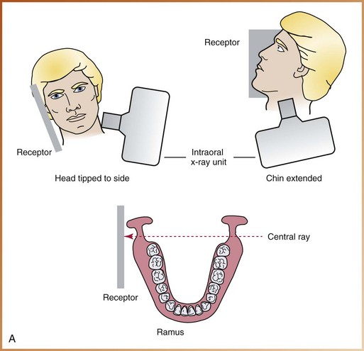
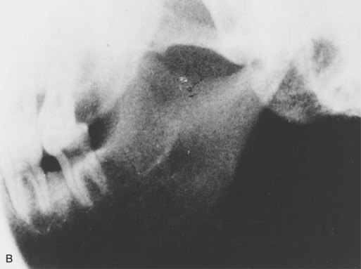
FIGURE 23-5 A, For the lateral jaw projection of the ramus of the mandible, proper patient positioning and receptor positioning are shown as viewed from the front and side of the patient. B, Example of lateral jaw image–ramus of mandible. (A and B, Courtesy of Dr. Robert M. Jaynes, Assistant Professor, Oral Radiology Group, The Ohio State University College of Dentistry.)
Receptor Placement: The cassette is placed flat against the patient’s cheek and is centered over the ramus of the mandible. The cassette is also positioned parallel with the ramus of the mandible. The patient must hold the cassette in position, with the thumb placed under the edge of the cassette and the palm placed against the outer surface of the cassette.
Head Position: The head is tipped approximately 15 degrees toward the side being imaged. The chin is extended and elevated slightly.
Skull Imaging
Skull imaging is used to examine the bones of the face and skull and is most often used in oral surgery and orthodontics. Although some skull projections can be exposed using a standard intraoral x-ray machine, most require the use of an extraoral unit and a cephalostat.
Images of the skull may be difficult to interpret because of the numerous anatomic structures that exist in a very small area; these structures often appear superimposed over each other. In many cases, multiple exposures may be necessary to obtain a clear view of the area in question. The most common skull images used in dentistry include the following:
Lateral Cephalometric Projection
Purpose: The purpose of the lateral cephalometric projection is to evaluate facial growth and development, trauma, and disease and developmental abnormalities. This projection demonstrates the bones of the face and skull as well as the soft tissue profile of the face (Figure 23-6).
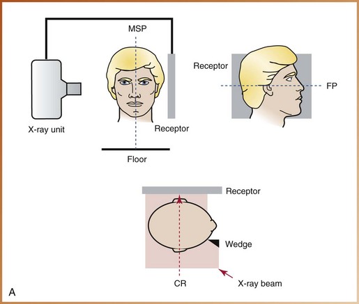
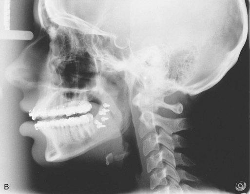
FIGURE 23-6 A, For the lateral cephalometric projection, proper patient positioning and receptor positioning are shown as viewed from the front, side, and top of the patient. MSP, Midsagittal plane; FP, Frankfort plane; CR, central ray. B, Example of lateral cephalometric image. (A and B, Courtesy of Dr. Robert M. Jaynes, Assistant Professor, Oral Radiology Group, The Ohio State University College of Dentistry.)
The soft tissue outline of the face is more readily seen on the resulting image when a filter is used. A filter is placed at the x-ray source or between the patient and the receptor and serves to remove some of the x-rays that pass through the soft tissue of the face, thus enhancing the image of the soft tissue profile of the face.
Receptor Placement: The cassette is placed perpendicular to the floor in a cassette-holding device. The long axis of the cassette is positioned horizontally.
Head Position: The left side of the patient’s head is positioned adjacent to the cassette. The midsagittal plane (an imaginary line that divides the face in half) must be aligned perpendicular to the floor and parallel to the cassette. The Frankfort plane (a line extending from the top of the ear canal to the bottom of the eye socket) is aligned parallel to the floor. The head is centered over the cassette.
Posteroanterior Projection
Purpose: The purpose of the posteroanterior projection is to evaluate facial growth and development, trauma, and disease and developmental abnormalities. This projection also demonstrates the frontal and ethmoid sinuses, the orbits, and the nasal cavity (Figure 23-7).
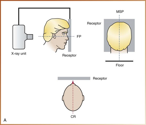
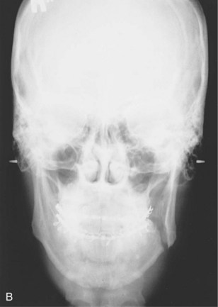
FIGURE 23-7 A, For the posteroanterior skull projection, proper patient positioning and receptor positioning are shown as viewed from the side, back, and top of the patient. MSP, Midsagittal plane; FP, Frankfort plane; CR, central ray. B, Example of a posteroanterior skull image. (A and B, Courtesy of Dr. Robert M. Jaynes, Assistant Professor, Oral Radiology Group, The Ohio State University College of Dentistry.)
Receptor Placement: The cassette is positioned perpendicular to the floor in a cassette-holding device. The long axis of the cassette is positioned vertically.
Head Position: The patient faces the cassette; the forehead and nose both touch the cassette. The midsagittal plane is aligned perpendicular to the floor, and the Frankfort plane is aligned parallel to the floor. The head is centered over the cassette.
Waters Projection
Purpose: The purpose of the Waters projection is to evaluate the maxillary sinus area. This projection also demonstrates the frontal and ethmoid sinuses, the orbits, and the nasal cavity (Figure 23-8).
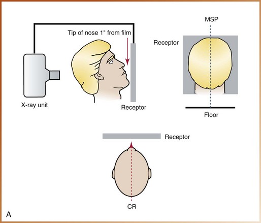

FIGURE 23-8 A, For the Waters projection, proper patient positioning and receptor positioning are shown as viewed from the side, back, and top of the patient. MSP, Midsagittal plane; CR, central ray. B, This case of chronic maxillary sinusitis secondary to an oroantral fistula shows thickening of the lining membrane (arrow) (Waters view). (A, Courtesy of Dr. Robert M. Jaynes, Assistant Professor, Oral Radiology Group, The Ohio State University College of Dentistry; B, from Pedersen GW: Oral surgery, Philadelphia, 1988, Saunders.)
Receptor Placement: The cassette is positioned perpendicular to the floor in a cassette-holding device. The long axis of the cassette is positioned vertically.
Head Position: The patient faces the cassette and elevates the chin; the chin touches the cassette, and the tip of the nose is positioned  to 1 inch away from the cassette. The midsagittal plane must be aligned perpendicular to the floor, and the head is centered over the cassette.
Submentovertex Projection
Purpose: The purpose of the submentovertex projection is to identify the position of the condyles, demonstrate the base of the skull, and evaluate fractures of the zygomatic arch. This projection also demonstrates the sphenoid and ethmoid sinuses and the lateral wall of the maxillary sinus (Figure 23-9).
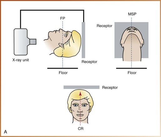
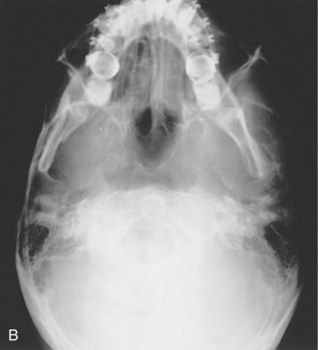
FIGURE 23-9 A, For the submentovertex projection, proper patient positioning and receptor positioning are shown as viewed from the side, front, and top of the patient. MSP, Midsagittal plane; FP, Frankfort plane; CR, central ray. B, Example of a submentovertex image. (A and B, Courtesy of Dr. Robert M. Jaynes, Assistant Professor, Oral Radiology Group, The Ohio State University College of Dentistry.)
Receptor Placement: The cassette is positioned perpendicular to the floor in a cassette-holding device. The long axis of the cassette is positioned vertically.
Head Position: The patient’s head and neck are tipped back as far as possible; the vertex (top) of the skull touches the cassette. Both the midsagittal plane and the Frankfort plane are aligned perpendicular to the floor. The head is centered on the cassette.
Reverse Towne Projection
Purpose: The purpose of the reverse Towne projection is to identify fractures of the condylar neck and ramus area (Figure 23-10).
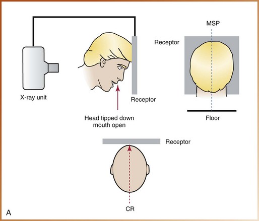
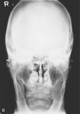
FIGURE 23-10 A, For the reverse Towne projection, proper patient positioning and receptor positioning are shown as viewed from the side, back, and top of the patient. MSP, midsagittal plane; CR, central ray. B, Example of a reverse Towne image. (A and B, Courtesy of Dr. Robert M. Jaynes, Assistant Professor, Oral Radiology Group, The Ohio State University College of Dentistry.)
Receptor Placement: The cassette is positioned perpendicular to the floor in a cassette-holding device. The long axis of the cassette is positioned vertically.
Head Position: The patient faces the cassette, with the head tipped down and the mouth open as wide as possible; the chin rests on the chest, and the top of the forehead touches the cassette. The midsagittal plane must be aligned perpendicular to the floor, and the head is centered on the cassette.
Temporomandibular Joint Imaging
The temporomandibular joint (TMJ) is the jaw joint. As the term temporomandibular indicates, this joint includes the temporal bone and the mandible. The glenoid fossa and the articular eminence of the temporal bone, the condyle of the mandible, and the articular disc between the bones make up the TMJ area. This area can be very difficult to examine on an image because of multiple adjacent bony structures.
Imaging cannot be used to examine the articular disc and other soft tissue areas of the TMJ; instead, specialized imaging techniques (e.g., arthrography and magnetic resonance imaging [MRI]) must be used. Imaging, however, can be used to show bone and the relationship of the joint components. For example, changes in bone (e.g., erosions, bony deposits) can be seen on TMJ images. The following two techniques are used in TMJ imaging:
Transcranial Projection (Lindblom Technique)
Purpose: The purpose of the transcranial projection is to evaluate the superior surface of the condyle and the articular eminence (Figure 23-11). This projection can also be used to evaluate movement of the condyle when the mouth is opened and to compare the joint spaces (right versus left).
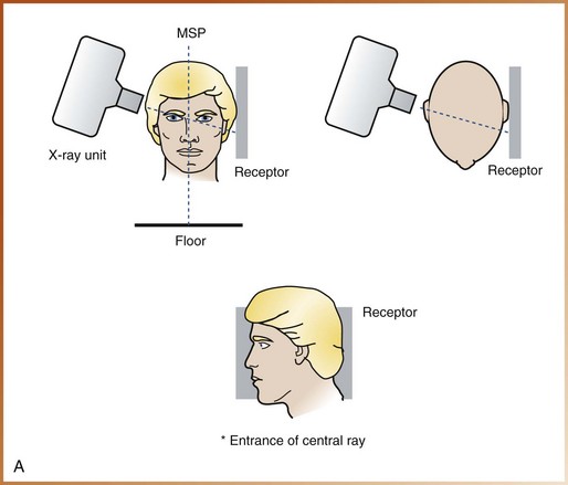
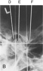
FIGURE 23-11 A, For the transcranial projection, proper patient positioning and receptor positioning are shown as viewed from the front, top, and side of the patient. MSP, midsagittal plane. B, Transcranial view of temporomandibular joint in the rest position. D, Glenoid fossa; E, head of mandibular condyle; F, articular eminence. (A, Courtesy of Dr. Robert M. Jaynes, Assistant Professor, Oral Radiology Group, The Ohio State University College of Dentistry; B, from Kasle MJ: An atlas of dental radiographic anatomy, ed 4, Philadelphia, 1994, Saunders.)
Receptor Placement: The cassette is placed flat against the patient’s ear and is centered over the TMJ.
Head Position: The midsagittal plane must be aligned perpendicular to the floor and parallel to the cassette.
Beam Alignment: The central ray is directed toward a point 2 inches above and 0.5 inch behind the opening of the ear canal. The beam is directed downward (+25 degrees) and forward (20 degrees) and is centered on the TMJ that is being imaged.
Exposure Factors: Exposure factors for the transcranial projection vary with the receptor, intensifying screens, and equipment used.
The intraoral x-ray unit can be used in the exposure of a transcranial projection. Special positioning devices can be used to coordinate the alignment of the receptor, the patient’s head, and the beam to obtain an accurate transcranial image. Such devices are also used to reproduce the same patient positioning in subsequent exposures, thereby permitting comparison of images.
Temporomandibular Joint Tomography
The technique of temporomandibular joint tomography is used to examine the TMJ. Tomography, as defined in Chapter 22, is a technique used to show structures located within a selected plane of tissue while blurring structures outside the selected plane. In TMJ tomography, this is accomplished by moving the receptor and x-ray tubehead in opposite directions around a fixed rotation point. The location of this rotation point determines what plane of the head will be imaged (Figure 23-12).
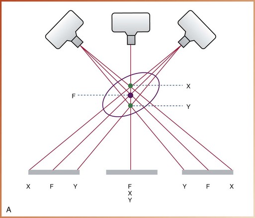
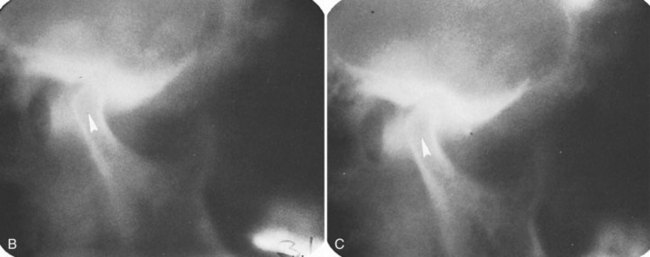
FIGURE 23-12 A, As the tubehead and the receptor move in opposite directions around the patient, objects in the image layer (F) appear sharp on the image. Objects on either side of the image layer (X, Y) are blurred. B and C, Corrected axis tomograms showing decreased joint space and posterior positioning of the left condyle (arrowheads) caused by the anteriorly placed meniscus. (A, Courtesy of Dr. Robert M. Jaynes, Assistant Professor, Oral Radiology Group, The Ohio State University College of Dentistry; B and C, From Kasle MJ: An atlas of dental radiographic anatomy, ed 4, Philadelphia, 1994, Saunders.)
TMJ tomography provides the most definitive imaging of the bony components of the TMJ. As a result, the condyle, the articular eminence, and the glenoid fossa can all be examined on an image known as the tomogram. In addition, the tomogram can be used to estimate joint space and evaluate the extent of movement of the condyle when the mouth is open.
A special tomographic x-ray unit is required for TMJ tomography. Most dental practitioners do not purchase such specialized equipment because of the prohibitive cost. Therefore, dental patients who require TMJ tomography are usually referred to a specialized imaging facility. Further discussion about the specifics of TMJ tomography is beyond the scope of this text.
Summary
• The extraoral receptor is placed outside the mouth during x-ray exposure.
• Uses of extraoral projections include (1) evaluation of large areas of skull and jaws; (2) evaluation of growth and development; (3) evaluation of impacted teeth; (4) detection of diseases, lesions, and conditions of the jaws; (5) examination of the extent of large lesions; (6) evaluation of trauma; and (7) evaluation of the TMJ area.
• Special equipment, including the x-ray unit, receptors, screen film, intensifying screens, grid, and cassette, is necessary for extraoral imaging.
• Before preparing the patient for exposure of an extraoral projection, the cassette must be prepared, infection control procedures completed, and exposure factors selected.
• After preparing the equipment, the dental radiographer must explain the imaging procedures to the patient, place the lead apron, and have the patient remove all radiodense objects from the head-and-neck region.
• A variety of projection techniques are used in extraoral imaging; the choice depends on what information is needed.
Danforth, RA, Dus, I, Mah, J. 3-D volume imaging for dentistry: a new dimension. J Calif Dent Assoc. 2003;31(11):817–823.
Frommer, HH, Savage-Stabulas, JJ, Extraoral techniques. Radiology for the dental professional, ed 9, St. Louis, Mosby, 2011.
Johnson, ON, McNally, MA, Essay, CE, Extraoral radiography. Essentials of dental radiography for dental assistants and hygienists, ed 8, Upper Saddle River, NJ, Pearson Education, Inc, 2007.
Miles, DA, Van Dis, ML, Jensen, CW, Williamson, GF, Extraoral radiography. Radiographic imaging for dental auxiliaries, ed 4, St. Louis, Saunders, 2009.
Miles, DA, Van Dis, ML, Razmus, TF. Plain film extraoral radiographic techniques. In: Basic principles of oral and maxillofacial radiology. Philadelphia: Saunders; 1992.
Olson, SS. Auxiliary radiographic techniques. In: Dental radiography laboratory manual. Philadelphia: Saunders; 1995.
White, SC, Pharoah, MJ, Advanced imaging. Oral radiology: principles of interpretation, ed 6, St. Louis, Mosby, 2009.
White, SC, Pharoah, MJ, Extraoral radiographic examinations. Oral radiology: principles of interpretation, ed 6, St. Louis, Mosby, 2009.
Essay
Describe the head position, receptor placement, and beam alignment for each of the following extraoral images:
Multiple Choice
________ 9. Which of the following projections is best for the examination of the maxillary sinus?
________ 10. Which of the following projections is best for the examination of fractures of the zygomatic arch?
________ 11. Which of the following projections is best for examination of fractures of the condylar neck?
________ 12. Which of the following projections is best for the examination of the soft tissue profile of the face?
________ 13. Which of the following projections is best for the examination of the condyle and articular eminence?
________ 14. Which of the following projections is best for the examination of fractures of the mandibular body?
________ 15. Which of the following projections is best for the examination of a large lesion in the ramus?