Panoramic Imaging
After completion of this chapter, the student will be able to do the following:
• Define the key terms associated with panoramic imaging
• Describe the purpose and uses of panoramic imaging
• Describe the fundamentals of panoramic imaging
• Describe the equipment used in panoramic imaging
• Describe patient preparation, equipment preparation, and patient-positioning procedures needed before exposing a panoramic projection
• Identify the patient-preparation and patient-positioning errors seen on panoramic images
• Discuss the causes of patient-preparation and patient-positioning errors and the necessary measures needed to correct such errors
• Discuss the advantages and disadvantages of panoramic imaging
It is often difficult, if not impossible, to obtain adequate diagnostic information from a series of intraoral images alone. Impacted third molar teeth, jaw fractures, and large lesions in the posterior mandible cannot always be seen well enough on intraoral projections; in such cases, the panoramic image is preferred. The panoramic image allows the dental professional to view a large area of the maxilla and the mandible on a single projection.
The purpose of this chapter is to present basic concepts of panoramic imaging and to describe the patient preparation, equipment preparation, and patient positioning procedures needed to perform this procedure. In addition, this chapter describes the advantages and disadvantages of panoramic imaging and reviews helpful hints.
Basic Concepts
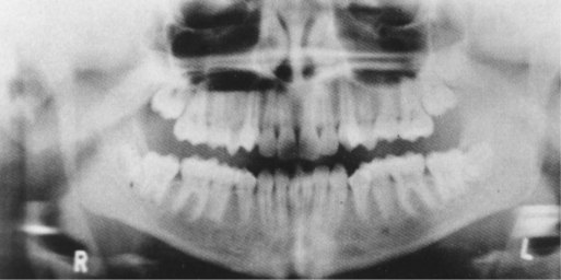
As the term panoramic suggests, a panoramic image shows a wide view of the maxilla and the mandible (Figure 22-1). Panoramic imaging is an extraoral technique that is used to examine the maxilla and the mandible on a single projection. As described in Chapter 6, an extraoral receptor is positioned outside the mouth during x-ray exposure. In panoramic imaging (also known as rotational panoramic imaging), both the receptor and the tubehead rotate around the patient, producing a series of individual images. When such images are combined, an overall view of the maxilla and the mandible is created.

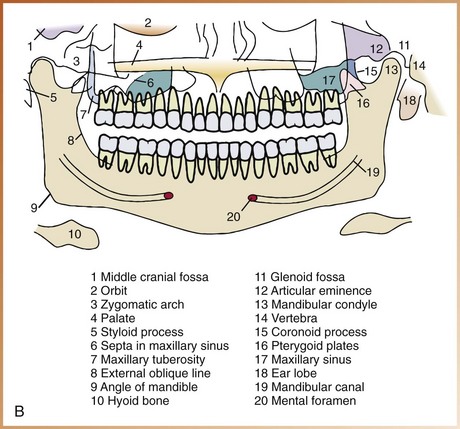
FIGURE 22-1 A, Panoramic image. B, Panoramic anatomy. (A from Miles DA, Van Dis ML, Jensen CW, et al: Radiographic imaging for dental auxiliaries, ed 2, Philadelphia, 1993, Saunders; B from Olson SS: Dental radiography laboratory manual, Philadelphia, 1995, Saunders.)
Purpose and Use
The panoramic image provides the dental radiographer with an overall view of the maxilla and the mandible and is often used to supplement bite-wing and periapical images. The panoramic image is typically used for the following purposes:
• To evaluate eruption patterns, growth, and development
• To detect diseases, lesions, and conditions of the jaws
The images on a panoramic projection are not as defined or sharp as the images seen on intraoral projections. Consequently, a panoramic image should not be used to evaluate and diagnose caries (Chapter 33), periodontal disease (Chapter 34), or periapical lesions (Chapter 35). The panoramic image should not be used as a substitute for intraoral projections.
Fundamentals
When intraoral images (e.g., periapical and bite-wing images) are exposed, the receptor and the x-ray tubehead remain stationary. In panoramic imaging, the receptor and the x-ray tubehead move around the patient. The x-ray tube rotates around the patient’s head in one direction, while the receptor rotates in the opposite direction (Figure 22-2). The patient may stand or sit in a stationary position, depending on the type of panoramic x-ray machine that is used. The movement of the receptor and the tubehead produces an image through the process known as tomography. Tomo- means section; tomography is an imaging technique that allows the imaging of one layer, or section, of the body while blurring the images of structures in other planes. In panoramic imaging, this image conforms to the shape of the dental arches.
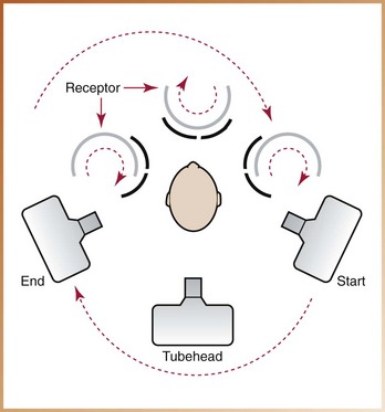
FIGURE 22-2 In panoramic imaging, the receptor and the x-ray tubehead move around the patient in opposite directions. (Courtesy of Dr. Robert M. Jaynes, Assistant Professor, Oral Radiology Group, The Ohio State University College of Dentistry.)
Rotation Center
In panoramic imaging, the receptor and the x-ray tubehead are connected and rotate simultaneously around a patient during exposure. The pivotal point, or axis, around which the receptor and the x-ray tubehead rotate is termed the rotation center. Depending on the manufacturer, the number and location of the rotational centers differ. One of three basic rotation centers is used in panoramic x-ray machines (Figure 22-3), as follows:
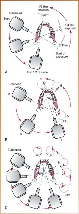
FIGURE 22-3 Types of panoramic x-ray machines. A, Double-center rotation machines have two rotational centers, one for the right and one for the left side of the jaws. B, Triple-center rotation machines have three centers of rotation and create an uninterrupted radiographic image of the jaws. C, Moving-center rotation machines rotate around a continuously moving center that is similar to the arches, creating an uninterrupted image of the jaws. (Redrawn from Olson SS: Dental radiography laboratory manual, Philadelphia, 1995, Saunders.)
In all cases, the center of rotation changes as the receptor and the tubehead rotate around the patient. This rotational change allows the image layer to conform to the elliptical shape of the dental arches. The location and number of rotational centers influence the size and shape of the focal trough.
Focal Trough
In panoramic imaging, the focal trough is a theoretical concept used to determine where the dental arches must be positioned to obtain the clearest image (Figure 22-4). The focal trough (also known as the image layer) can be defined as a three-dimensional curved zone in which structures are clearly demonstrated on a panoramic image. The structures located within the focal trough appear reasonably well defined on the resulting panoramic image. The structures positioned inside or outside of the focal trough appear blurred or indistinct and are not readily visible on the panoramic image.
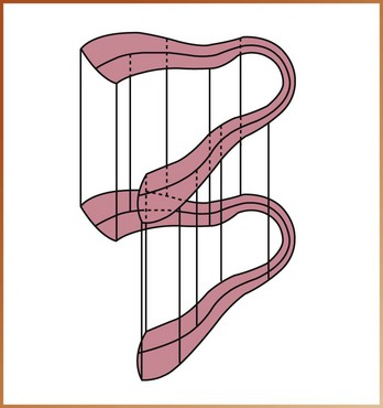
FIGURE 22-4 Example of an “image layer” or “focal trough.” (Courtesy of Carestream Health, Inc. Rochester, NY.)
The size and shape of the focal trough vary, depending on the manufacturer of the panoramic x-ray unit. The closer the rotation center is to teeth, the narrower is the focal trough. In most panoramic x-ray machines, the focal trough is narrow in the anterior region and wide in the posterior region.
Each panoramic x-ray unit has a focal trough that is designed to accommodate the average jaw. Each manufacturer provides specific instructions about patient positioning to ensure that the teeth are positioned within the focal trough. The quality of the resulting panoramic image depends on the positioning of the patient’s teeth within the focal trough and how closely the patient’s maxilla and mandible conform to the focal trough designed for the average jaw.
Equipment
The use of special equipment, including the panoramic x-ray unit, the receptor, and—when using film—screen film, intensifying screens, and cassette, is necessary in panoramic imaging.
Panoramic X-Ray Units
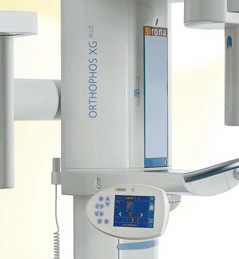
A number of different panoramic x-ray units are available, including the Orthophos XG Plus (Sirona USA) and the Orthoralix 8500 (Gendex Dental Systems) (Figure 22-5). Panoramic units may differ with regard to the number of the rotation centers, the size and shape of the focal trough, and the type of receptor transport mechanism used. Although each manufacturer’s panoramic unit is slightly different, all panoramic machines have similar components. The main components of the panoramic unit include the following (Figure 22-6):
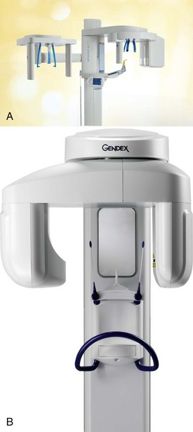
FIGURE 22-5 A, Orthophos XG Plus extraoral x-ray machine. B, Orthoralix 8500 extraoral x-ray machine. (A, Courtesy of Sirona USA, Charlotte, NC; B, courtesy of Gendex Dental Systems, Des Plaines, IL.)
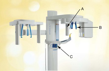
FIGURE 22-6 Main components of the Orthophos XG Plus: A, X-ray tubehead; B, head positioner; C, exposure controls. (Courtesy of Sirona USA, Charlotte, NC.)
The panoramic x-ray tubehead is similar to an intraoral x-ray tubehead; each has a filament used to produce electrons and a target used to produce x-rays. The collimator used in the panoramic x-ray tubehead, however, differs from the collimator used in the intraoral x-ray tubehead. As described in Chapter 5, the collimator used in the intraoral x-ray machine is a lead plate with a small round or rectangular opening in the middle. The function of the collimator is to restrict the size and shape of the x-ray beam. The collimator used in the panoramic x-ray machine is a lead plate with an opening in the shape of a narrow vertical slit (Figure 22-7).
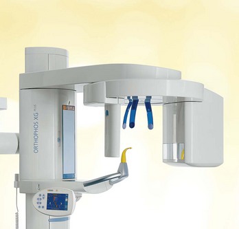
FIGURE 22-7 The collimater on the Orthophos XG Plus has a narrow slit opening. (Courtesy of Sirona USA, Charlotte, NC.)
The x-ray beam emerges from the panoramic tubehead through the collimator as a narrow band. The beam passes through the patient and then exposes the receptor through another vertical slit in the cassette carrier (the metal holder that supports the cassette). The narrow x-ray beam that emerges from the collimator minimizes patient exposure to x-radiation.
The vertical angulation of the panoramic tubehead does not vary as in the case of the intraoral tubehead. The tubehead of the panoramic unit is fixed in position so that the x-ray beam is directed slightly upward. In addition, the tubehead of the panoramic unit always rotates behind the patient’s head, while the receptor rotates in front of the patient.
Each panoramic unit has a head positioner, which is used to align the patient’s teeth as accurately as possible in the focal trough. The typical head positioner consists of a chin rest, notched bite-block, forehead rest, and lateral head supports or guides (Figure 22-8). Each panoramic unit is different, and the operator must follow the manufacturer’s instructions on how to position the patient’s head in the focal trough.
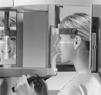
FIGURE 22-8 The head positioner (notched bite-block, forehead rest, and lateral head supports) is used to align the patient’s teeth to the focal trough. (Courtesy of Sirona USA, Charlotte, NC.)
Each panoramic unit has exposure factors that are determined by the manufacturer, who provides suggested exposure factors (milliamperage and kilovoltage) in the instruction manual for the x-ray machine. The milliamperage and kilovoltage settings are adjustable and can be varied to accommodate patients of different sizes (Figure 22-9). The exposure time, however, is fixed and cannot be changed.
Film
Screen film is used in panoramic imaging; this film is sensitive to the light emitted from intensifying screens (see Chapter 7). A screen film is placed between two intensifying screens in a cassette holder. When the cassette holder is exposed to x-rays, the screens convert the x-ray energy into light, which, in turn, exposes the screen film. Some screen films are sensitive to green light (Kodak T-Mat G and Ortho G film), whereas others are sensitive to blue light (Kodak X-Omat RP and Ektamat G films). Blue-sensitive film must be paired with screens that produce blue light, and green-sensitive film must be paired with screens that produce green light. The film used in panoramic imaging is available in two sizes: 5 × 12 inch and 6 × 12 inch.
Intensifying Screens
Two basic types of intensifying screens are used: calcium tungstate and rare earth (see Chapter 7). Calcium tungstate screens emit blue light, and the rare earth screens emit green light. Rare earth screens require less x-ray exposure than do calcium tungstate screens and are considered “faster.” Consequently, rare earth screens are recommended in panoramic imaging because of less exposure of the patient to radiation.
Cassette
The cassette is a device that is used to hold the extraoral film and intensifying screens (see Chapter 7). The cassette may be rigid or flexible, curved or straight, depending on the panoramic x-ray unit (Figure 22-10). All cassettes must be “light-tight” to protect the film from exposure. One intensifying screen is placed on each side of the film and held in place when the cassette is closed.
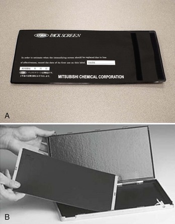
FIGURE 22-10 A, A flexible panoramic cassette has an opening at one end for the receptor. B, A rigid panoramic cassette. (A, Courtesy of Instrumentarium Dental Inc.; B, Courtesy of Gendex Dental Systems, Des Plaines, IL.)
The cassette must be marked to orient the finished image. Before exposure, a metal letter “R” can be attached to the front of the cassette to indicate the patient’s right side; the letter “L” is used to identify the patient’s left side (Figure 22-11). Special labeling may also be attached to indicate the patient’s name, the dentist’s name, and the date. If the cassette is not labeled before exposure, the film must be labeled immediately after processing. A marking pen or adhesive label can be used to label the image.
Step-by-Step Procedures
Step-by-step procedures for the exposure of a panoramic receptor include equipment preparation, patient preparation, and patient positioning. Before exposing a panoramic receptor, infection control procedures (as described in Chapter 15) must be completed.
Equipment Preparation
The dental radiographer must complete equipment preparations before preparing the patient for the exposure of a panoramic receptor (Procedure 22-1).
Patient Preparation
After preparing the panoramic equipment, the dental radiographer must prepare the patient for the procedure (Procedure 22-2).
PROCEDURE 22-2 Patient Preparation for Panoramic Imaging
1. Explain to the patient the imaging procedure about to be performed.
2. Place a lead apron, without a thyroid collar, on the patient, and secure it. A double-sided lead apron (one that protects the front and back of the patient) is recommended (Figure 22-12). The lead apron must be placed low around the neck so that it does not block the x-ray beam. A thyroid collar is not recommended for panoramic imaging because it blocks part of the beam and obscures important diagnostic information.
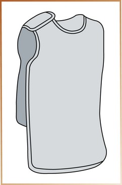
FIGURE 22-12 A double-sided lead apron is recommended for use during exposure of a panoramic receptor.
3. Have the patient remove all objects from the head-and-neck area that may interfere with the procedure. The patient must remove eyeglasses, earrings, necklaces, napkin chains, hearing aids, hairpins, and complete or partial dentures.
Patient Positioning
The dental radiographer must be familiar with the manufacturer’s specific directions for patient positioning that are included in the instruction manual. Although each manufacturer’s positioning and exposure procedures are slightly different, the patient positioning steps listed here are common to all panoramic machines (Procedure 22-3).
PROCEDURE 22-3 Patient Positioning for Panoramic Imaging
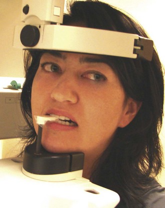
1. Instruct the patient to sit or stand “as tall as possible” with the back erect. The vertebral column must be perfectly straight. The spinal column is very dense; if the spine is not straight, a white shadow appears over the middle of the image and obscures diagnostic information.
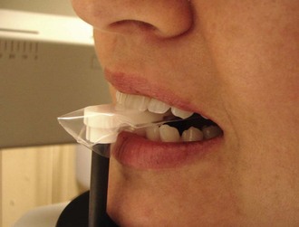
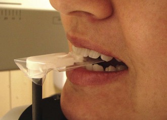
2. Instruct the patient to bite on the plastic bite-block. Maxillary and mandibular anterior teeth must be in an end-to-end position in the groove (notch) on the bite-block (Figure 22-13). This groove is used to align the teeth to the focal trough. (In an edentulous patient, the radiographer must align the patient’s maxillary and mandibular ridges over the notched area on the bite-block. Cotton rolls can be placed on each side of the bite-block to provide stabilization for the patient.)
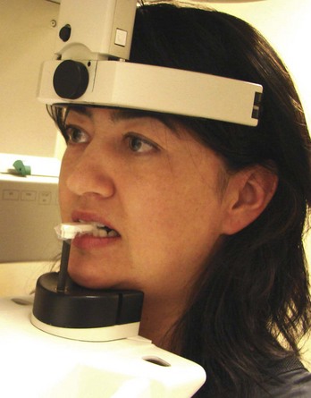
3. Position the midsagittal plane (an imaginary line that divides the patient’s face into right and left sides) perpendicular to the floor (Figure 22-14). The patient’s head must not be tipped or tilted; if the midsagittal plane is not positioned perpendicular to the floor, a distorted image results.
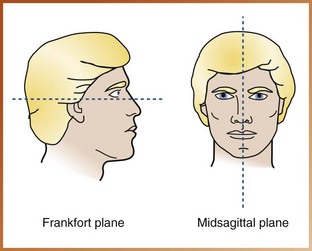
FIGURE 22-14 Frankfort and midsagittal planes. The Frankfort plane passes through the floor of the orbit and the external auditory meatus. The midsagittal plane divides the body in half into right and left sides. (From Olson SS: Dental radiography laboratory manual, Philadelphia, 1995, Saunders.)
4. Position the Frankfort plane (an imaginary plane that passes through the top of the ear canal and the bottom of the eye socket) parallel to the floor (Figure 22-15). When the Frankfort plane is parallel to the floor, the occlusal plane is positioned at the correct angle.
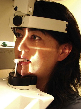
FIGURE 22-15 The patient’s head must be positioned such that the Frankfort plane is parallel to the floor.
5. Instruct the patient to place the tongue on the roof of the mouth. You may suggest that the patient “swallow and feel the tongue rise up to the roof of the mouth” and then instruct the patient to keep the tongue in that position during the procedure. Also, instruct the patient to close the lips around the bite-block.
6. After the patient has been positioned, instruct the patient to remain still while the machine is rotating during exposure.
7. Expose the receptor and if using film, proceed with film processing as described in Chapter 9.
Common Errors
To produce a diagnostic panoramic image and minimize patient exposure, mistakes must be avoided. The dental radiographer must be able to recognize common patient-preparation and patient-positioning errors and understand the necessary steps to correct these errors.
Patient-Preparation Errors
Proper patient preparation is critical in obtaining a diagnostic panoramic image. Two common patient preparation errors are (1) ghost images and (2) the lead apron artifact.
Ghost Images
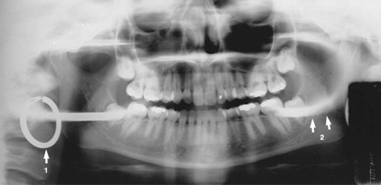
Problem: If all metallic or radiodense objects (e.g., eyeglasses, earrings, necklaces, hairpins, removable partial dentures, complete dentures, orthodontic retainers, hearing aids, napkin chains) are not removed before the exposure of a panoramic receptor, it results in a ghost image that obscures diagnostic information.
A ghost image, which is a radiopaque artifact seen on a panoramic image, is produced when a radiodense object is penetrated twice by the x-ray beam. A ghost image resembles its real counterpart and is found on the opposite side of the image; it appears indistinct, larger, and higher than its actual counterpart. For example, a ghost image of a hoop earring appears on the opposite side of the image as a radiopacity that is larger and higher than the real hoop earring. In addition, the ghost image of the hoop earring appears blurred in both horizontal and vertical directions (Figure 22-16).
Lead Apron Artifact
Problem: If the lead apron is incorrectly placed on the patient, or if a lead apron with a thyroid collar is used during the exposure of a panoramic projection, it results in a radiopaque cone-shaped artifact that obscures diagnostic information (Figure 22-17).
Patient-Positioning Errors
Patient positioning is of critical importance during exposure of a panoramic projection. Because the panoramic image does not show the fine anatomic details seen on intraoral radiographs, even the smallest positioning error can create a distorted image.
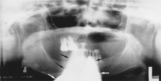
Positioning of Lips and Tongue
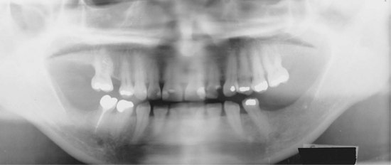
Problem: If the patient’s lips are not closed on the bite-block during the exposure of a panoramic projection, it results in a dark radiolucent shadow that obscures anterior teeth. If the tongue is not in contact with the palate during the exposure of a panoramic projection, it results in a dark radiolucent shadow that obscures the apices of the maxillary teeth (Figure 22-18).
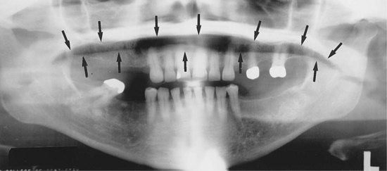
FIGURE 22-18 If the patient does not place his or her tongue on the roof of the mouth and hold it there throughout the imaging procedure, a radiolucent shadow will be superimposed over the image of the apices of maxillary teeth. (From Haring JI, Lind LJ: Radiographic interpretation for the dental hygienist, Philadelphia, 1993, Saunders.)
Solution: To prevent such errors, the dental radiographer must instruct the patient to close the lips around the bite-block. The patient must then be instructed to swallow once; after this, the patient must be asked to raise the tongue up to the palate and hold it against the hard palate during the exposure of the projection.
Positioning of Frankfort Plane Upward
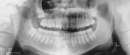
Problem: If the patient is positioned such that the chin is too high or is tipped up (Figure 22-19), the Frankfort plane is angled upward, and the following results:

1. The hard palate and floor of the nasal cavity appear superimposed over the roots of maxillary teeth.
2. A loss of detail in the maxillary incisor region occurs.
3. The maxillary incisors appear blurred and magnified.
4. A “reverse smile line” (curved downward) is seen on the image (Figure 22-20).
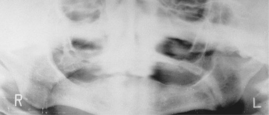
Positioning of Frankfort Plane Downward
Problem: If the patient is positioned such that the chin is too low or is tipped down (Figure 22-21), the Frankfort plane is angled downward, and the following results:
1. The mandibular incisors appear blurred.
2. A loss of detail in the anterior apical region occurs.
3. The mandibular condyles may not be visible.
4. An “exaggerated smile line” (curved upward) is seen on the image (Figure 22-22).
Aligning Teeth Anterior to the Focal Trough
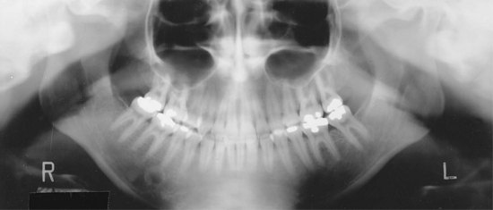
Problem: If the patient is positioned such that the anterior teeth are not aligned to the focal trough, as indicated by the groove in the bite-block, teeth appear blurred. If the patient’s teeth are too far forward on the bite-block or anterior to the focal trough (Figure 22-23), anterior teeth appear “skinny” and out of focus on the image (Figure 22-24).
Solution: To prevent such an error, the dental radiographer must position the patient such that the anterior teeth are in an end-to-end position in the groove on the bite-block. The forehead support must then be adjusted to stabilize the patient’s head position and prevent the patient from sliding forward on the bite-block.
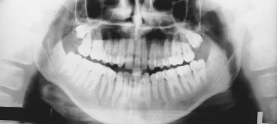
Aligning Teeth Posterior to the Focal Trough
Problem: If the patient’s anterior teeth are not aligned to the focal trough, as indicated by the groove in the bite-block, the teeth appear blurred. If the patient’s anterior teeth are aligned too far back on the bite-block or posterior to the focal trough (Figure 22-25), the teeth appear “fat” and out of focus on the image (Figure 22-26).
Aligning the Midsagittal Plane
Problem: If the patient’s head is not centered (Figure 22-27), the ramus and posterior teeth appear unequally magnified on the panoramic image. The side farthest from the receptor appears magnified, and the side closest to the receptor appears smaller (Figure 22-28).
Solution: To prevent such an error, the dental radiographer must position the patient’s head such that the midsagittal plane is perpendicular to the floor while the midline is centered on the bite-stick. The lateral head supports must then be adjusted to stabilize the position of the patient’s head.
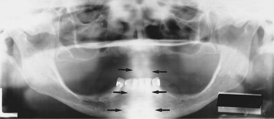
Aligning the Spine
Problem: If the patient is not standing or sitting with the spine straight, the cervical spine appears as a radiopacity in the center of the image and obscures diagnostic information (Figure 22-29).
Advantages and Disadvantages
As with all radiographic techniques, panoramic imaging has both advantages and disadvantages.
Advantages of Panoramic Imaging
1. Field size. The panoramic image covers the entire maxilla and mandible. More anatomic structures can be viewed on a panoramic image than with a complete mouth radiographic series (CMRS). In addition, lesions and conditions of the jaws that may not be seen on intraoral images can be detected on a panoramic image.
2. Simplicity. Exposure of a panoramic receptor is relatively simple and requires minimal amounts of time and training for the dental radiographer.
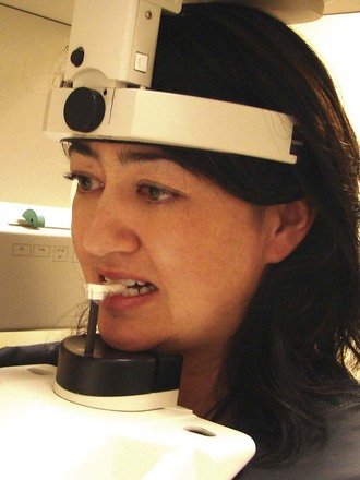
3. Patient cooperation. The exposure of a panoramic image is more acceptable to the patient because no discomfort is involved. For example, children who may not be able to tolerate intraoral projections may find it easier to sit still during the exposure of a panoramic image (Figure 22-30).
4. Minimal exposure. A panoramic image involves only minimal radiation exposure of the patient.
Disadvantages of Panoramic Imaging
1. Image quality. The images seen on a panoramic image are not as sharp as intraoral projections because of the intensifying screens. As a result, the panoramic image cannot be used to evaluate dental caries, periodontal disease, or periapical lesions.
2. Focal trough limitations. Objects of interest that are located outside the focal trough cannot be seen.
3. Distortion. Certain amounts of magnification, distortion, and overlapping are present on a panoramic image, even when proper technique is used.
4. Equipment cost. The cost of a panoramic x-ray unit is relatively high compared with the cost of an intraoral x-ray unit.
Helpful Hints
For exposing panoramic radiographs:
 DO cover the bite-block with a disposable plastic cover slip before positioning the patient.
DO choose the exposure factors (kilovoltage, milliamperage) according to the manufacturer’s recommendations before positioning the patient.
DO briefly explain to the patient the imaging procedure that is about to be performed.
DO place a lead apron without a thyroid collar on the patient, and secure it.
DO ask the patient to remove all radiodense objects from the head-and-neck area before positioning the patient.
DO instruct the patient to stand or sit “as straight and tall as possible.”
DO instruct the patient to place his or her front teeth in the deep groove on the bite-block in an end-to-end position.
DO position the midsagittal plane of the patient perpendicular to the floor.
DO position the Frankfort plane of the patient parallel with the floor.
DO instruct the patient to close the lips on the bite-block and to swallow once; then ask the patient to place the tongue against the roof of the mouth and to maintain that position during the exposure.
DO instruct the patient to remain still during the exposure.
Summary
• The panoramic image allows the dental professional to view a large area of the maxilla and the mandible on a single projection.
• Uses of the panoramic image include (1) evaluation of impacted teeth; (2) evaluation of eruption patterns and growth and development; (3) detection of diseases, lesions, and conditions of the jaws; (4) examination of extent of large lesions; and (5) evaluation of trauma.
• The panoramic image is typically used to supplement bite-wing and periapical images and is not a substitute for intraoral projections. The panoramic image should not be used to evaluate caries, periodontal disease, or periapical lesions.
• In panoramic imaging, both the receptor and the tubehead are connected and rotate simultaneously around the patient during exposure. Rotational centers allow the image layer to conform to the elliptical shape of the dental arches. The number and locations of rotational centers influence the size and shape of the focal trough.
• The focal trough is a three-dimensional curved zone in which structures are clearly demonstrated on a panoramic image. Structures within the focal trough appear reasonably well defined, whereas structures outside the focal trough appear blurred.
• Special equipment, including the panoramic x-ray unit, the receptor, and—when using film—screen film, intensifying screens, and cassette, is necessary for the panoramic imaging procedure.
• Before preparing the patient for exposure of a panoramic projection, the following tasks must be completed: preparation of the cassette, infection control procedures, selection of the exposure factors, adjustment of the panoramic x-ray machine according to patient height and proper alignment of movable parts, and loading of the cassette into the cassette carrier.
• After preparing the equipment, the dental radiographer must prepare the patient by explaining the imaging procedure, placing the lead apron on the patient, and having the patient remove all radiodense objects from the head-and-neck region.
• The patient must then be positioned according to the manufacturer’s recommendations for the alignment of the spine, teeth, the midsagittal plane, the Frankfort plane, lips, and the tongue.
• The dental radiographer must be able to identify patient-preparation and patient-positioning errors and know the necessary steps to correct such errors.
• Advantages of panoramic imaging include field size, simplicity of use, patient cooperation, and minimal patient exposure to x-radiation.
• Disadvantages of panoramic imaging include image quality, limitations imposed by the focal trough, image distortion, and the high cost of equipment.
Frommer, HH, Savage-Stabulas, JJ, Panoramic radiography. Radiology for the dental professional, ed 9, St. Louis, Mosby, 2011.
Johnson, ON, McNally, MA, Essay, CE, Panoramic radiography. Essentials of dental radiography for dental assistants and hygienists, ed 6, Norwalk, CT, Appleton & Lange, 1999.
Miles, DA, Van Dis, ML, Jensen, CW, Williamson, GF, Panoramic imaging. Radiographic imaging for the dental team, ed 4, Philadelphia, Saunders, 2009.
Miles, DA, Van Dis, ML, Razmus, TF. Plain film extraoral radiographic techniques. In: Basic principles of oral and maxillofacial radiology. Philadelphia: Saunders; 1992.
Olson, SS. Auxiliary radiographic techniques. In: Dental radiography laboratory manual. Philadelphia: Saunders; 1995.
White, SC, Pharoah, MJ, Panoramic imaging. Oral radiology: principles of interpretation, ed 6, St. Louis, Mosby, 2009.
Multiple Choice
________ 1. Which of the following describes a use of a panoramic image?
________ 2. The zone in which structures are clearly demonstrated on a panoramic image is termed:
________ 3. Rare earth intensifying screens are recommended in panoramic imaging because:
a. rare earth screens emit a blue light
b. rare earth screens provide a more diagnostic image
c. rare earth screens require less x-ray exposure for the patient
________ 4. A thyroid collar is not recommended in panoramic imaging because:
a. it blocks the x-ray beam and obscures information
b. there is a relatively low dose of radiation to the thyroid gland in panoramic imaging
________ 5. The imaginary line that passes from the bottom of the eye socket through the top of the ear canal is termed:
Matching
For questions 6 to 20, match the following types of procedures with the statements given below.
________ 6. The receptor and the tubehead rotate around the patient.
________ 7. This type of image is used to examine the extent of large lesions.
________ 8. The dental arches must be aligned to the focal trough.
________ 9. The tubehead contains a filament used to produce electrons and a target used to produce x-rays.
________ 10. The collimator is a lead plate with an opening in the shape of a narrow vertical slit.
________ 11. The collimator is a lead plate with a small, round or rectangular opening.
________ 12. The vertical angulation of the tubehead is variable.
________ 13. A head positioner is used to position the patient’s head.
________ 14. A screen film is used.
________ 15. A cassette holder with two intensifying screens is used.
________ 16. The x-ray film must be loaded into a cassette in a darkroom under safelight conditions.
________ 17. A lead apron with a thyroid collar must be placed on the patient.
________ 18. All jewelry (earrings and necklaces) must be removed before exposure.
________ 19. The midsagittal plane must be positioned perpendicular to the floor.
________ 20. The vertebral column must be perfectly straight.
Essay
21. Discuss the equipment preparations necessary before exposure of a panoramic projection.
22. Discuss the patient preparations necessary before exposure of a panoramic projection.
23. Discuss the patient positioning steps necessary before exposure of a panoramic projection.
24. Give examples of Frankfort plane positioning errors, and discuss what steps can be taken to correct such errors.
25. Discuss the advantages and disadvantages of panoramic imaging.
Identification
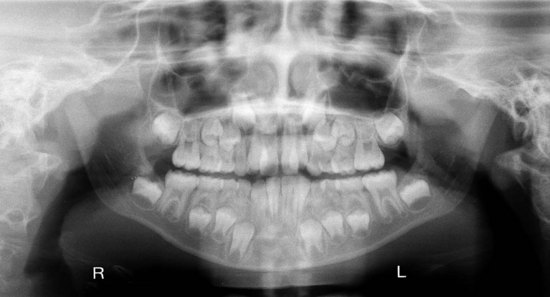
26. Identify the approximate age of the patient in Figure 22-31.
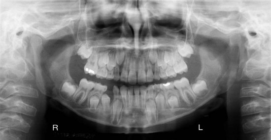
FIGURE 22-31
27. Identify the approximate age of the patient in Figure 22-32.
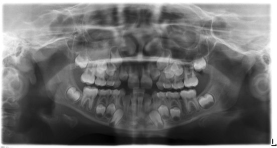
FIGURE 22-32 (Courtesy of Cary Pediatric Dentistry, Cary, NC.)
28. Identify the approximate age of the patient in Figure 22-33.
FIGURE 22-33 (Courtesy of Cary Pediatric Dentistry, Cary, NC.)