Chapter 12 The motor principle
Chapter contents
12.1 Aim 71
12.2 Introduction and definition of the motor principle 71
12.3 Direction and magnitude of the force on the conductor 72
12.4 Convention for the direction of the force 72
12.5 Interaction of two electromagnetic fields 73
12.6 The DC electric motor 74
12.7 The AC induction motor 74
12.8 Magnetic deflection of an electron beam 75
12.9 The motor principle in radiography 76
Further reading 76
12.1 Aim
The aim of this chapter is to consider the motor principle. The application of this principle to the direct current (DC) motor and the alternating current (AC) induction motor will be considered, as will the magnetic deflection of electrons. Finally, the relevance of these to radiography will be discussed.
12.2 Introduction and definition of the motor principle
In Chapter 9, we considered the topic of electromagnetism where a magnetic field was produced by an electric current. This chapter considers what happens when an electromagnetic field is created in the presence of another magnetic field. If we consider two bar magnets lying in close proximity to one another, then (depending on their orientation) a force of repulsion or attraction will exist between them (see Ch. 8). If one of the bar magnets is now replaced by a solenoid (see Sect. 9.6), we would expect a force between the solenoid and the bar magnet when an electric current is passed through the solenoid, since it behaves like a bar magnet under these circumstances. This force will cause the solenoid to move if it is free to do so. When the current is switched off, the magnetic field due to the solenoid disappears and so does the force between it and the magnet. This interaction between electromagnetism and another magnetic field is known as the motor principle (or motor effect) and may be formally defined:
The principle of the electric motor is that it converts electrical energy into kinetic energy (mechanical energy) through the interaction of the two magnetic fields.
12.3 Direction and magnitude of the force on the conductor
Consider a length L of straight wire which is carrying an electric current I, the whole wire being placed in a uniform magnetic flux density B, as shown in Figure 12.1. In this diagram, it is assumed that the direction of B and of the wire are both in the plane of the paper. Experimentally, the following results are observed:
• The direction of the force on the wire is always into or out of the paper, i.e. at right angles to the direction of B and I.
• The direction of the force on the wire is reversed if the current is reversed.
• The magnitude of the force is proportional to:
 the sine of the angle between the direction of B and I, i.e. sin θ in Figure 12.1. Thus, the force on the wire is at its maximum when the wire is at right angles to the field (sin 90°=1) and zero when the wire is parallel to the field (sin 0°=0).
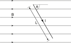
Figure 12.1 The interaction of the permanent magnetic field, B, with the magnetic field caused by the current, I, flowing through the wire causes a force to act on the wire – the motor principle.
Combining the factors in the last bullet point above, we have:

where the force, F, is in newtons, B in tesla, I in amperes and L in metres.
The findings discussed above may be used to define the tesla as follows:
A magnetic flux density of 1 tesla (T) exists if the force on a straight wire of length 1 metre is 1 newton when the wire carries a current of 1 ampere and is placed at right angles to the direction of magnetic flux.
The direction of the force on the current-carrying conductor may be obtained using the appropriate rule or convention. As we saw before, in Chapter 10, Fleming’s right- and left-hand rules were produced to deal with ‘conventional current’ and not electron flow. To avoid confusion, a different convention will be presented to calculate the direction of the force on the current-carrying conductor.
12.4 Convention for the direction of the force
Consider the situation shown in Figure 12.2A. Here a wire is carrying an electric current such that the electrons are flowing away from the eye of the observer into the paper. The magnetic field, H, produced by this current is in an anticlockwise direction, as shown. If an external magnetic field, B, is applied to the wire as shown, it is found that the wire experiences a force, F, which pushes it to the right. Figure 12.2B shows the convention which will be used to determine the direction of the force – this is similar in many ways to the convention used in Section 10.6 to determine the direction of the induced current. The direction of the force can be determined as follows:
1. Mark the position of the wire, and draw the direction of electron flow and the magnetic field around it. In Figure 12.2B, this is an anticlockwise magnetic field as the electrons are flowing away from us.
2. Align one of the lines of force from the external magnetic field (B) so that it touches the field around the wire at the point where both fields are in the same direction. This occurs at point A in Figure 12.2B
3. Now draw a line from this point through the wire (AF). The direction in which you draw this line indicates the direction of the force acting on the wire. This line is drawn from left to right in this case, agreeing with the previous findings.
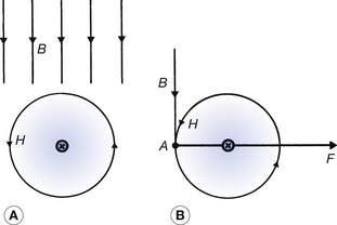
Figure 12.2 Convention for establishing the force acting on a current-carrying conductor placed in a magnetic field. For an explanation of how to use the convention, see the text.
This procedure can be applied to any direction of current and any orientation of the wire and the magnetic field. In some cases, however, the applied magnetic field is not exactly perpendicular to the wire and so cannot be made to line up to the field produced by it, as described so far. In this situation, the applied magnetic field may be split into two components: one parallel to the wire (which produces no force on the wire) and one perpendicular to the wire (which will produce a force on the wire according to the above convention). The following examples should help to clarify the above points.
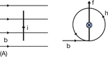
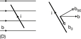
a. The situation of the wire and the external magnetic field is shown in the left-hand diagram below. In the right-hand diagram, the observer is looking along the wire (as if looking from the bottom of the page). The convention described previously can now be applied, giving an upward direction of force.
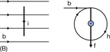
b. In this case, when we draw the right-hand diagram, the electrons will be flowing towards the observer and so the magnetic field around the wire will be in a clockwise direction. By applying the convention, it can be found that the force is downwards into the paper (the opposite of the previous situation).
c. In diagram C, the wire and the lines of flux are parallel and so no force will be experienced by the wire when current flows through it.

d. In the situation shown in diagram D, the wire is not at 90° to the lines of flux and so these must be split into two components, B0, which is parallel to the wire and B90, which is at right angles to it. This is shown in the right-hand diagram. As described in the previous example, the field, which is parallel to the wire (B0), will have no effect on it and so can be ignored. Application of the convention now shows that the force acting on the wire will be in an upwards direction, as in the first example.
12.5 Interaction of two electromagnetic fields
So far in this chapter we have seen that a force exists on a current-carrying conductor when it is in the presence of a magnetic field and that this is known as the motor principle. It is immaterial whether the magnetic field interacting with the conductor is from a permanent magnet or whether it is produced electromagnetically. In this way, if two current-carrying solenoids are held close together, they behave in the same way as two bar magnets with a north pole at one end of the solenoid and a south pole at the other. Thus, the solenoids will attract or repel each other depending on the orientation in which they are placed: like poles repel and unlike poles attract.
12.5.1 Two parallel wires of infinite length
This rather improbable situation is used in the International System of Units (SI) system to define the ampere and so will be considered here.
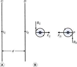
Figure 12.3 (see page 74) shows two parallel wires C and D carrying currents IC and ID respectively. Figure 12.3A shows the plan view of the wires while Figure 12.3B is the view obtained by looking along the wires towards C and D where the electron flow is into the paper for both wires. The magnetic field around each wire will consist of a series of concentric circles with the field being in an anticlockwise direction. We will now consider how the magnetic field of one wire will interact with the magnetic field of the other. The magnetic field from wire C (BC) is ‘upwards’ at wire D while the field from wire D (BD) is ‘downwards’ at wire C. If we now apply our convention to this situation, we can see that we get forces FC and FD, as shown in Figure 12.3B. Thus, there is a mutual force of attraction between the wires. This situation is used as the basis of the definition of the ampere in the SI system:
12.6 The DC electric motor
The electric motor is, of course, the prime example of the motor principle in that it converts electrical energy into mechanical energy. To understand the workings of the electric motor we need to understand the motor principle and also electromagnetic induction (see Ch. 10). A simplified DC electric motor is shown in Figure 12.4, where a battery is connected to a coil of wire KLMN via brushes B at a commutator C. The coil of wire is in the magnetic field of a permanent magnet, the direction of whose field is from left to right in the figure.
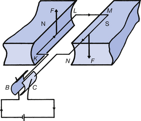
When the current is switched on, the electron flow is in the direction indicated in the diagram, and the coil is affected by a clockwise force due to the motor principle (i.e. an upward force on KL and a downward force on MN, as may be verified using the convention in Sect. 12.4). The commutator C turns with the coil KLMN so that the current always flows in the same direction relative to the permanent magnet. Hence, the coil always experiences a clockwise force and keeps turning. Without the commutator, KLMN would eventually stop at right angles to the permanent magnetic field.
Since a clockwise force is being continuously applied to the coil, it would seem logical to assume that the speed of rotation would continuously increase. This does not, in fact, happen. The speed of rotation increases up to a certain rate and then remains constant. To understand why this happens, we need to look at electromagnetic induction. We have a conductor KLMN which is moving relative to a magnetic field, i.e. undergoing a change of magnetic flux, so an electromotive force (EMF) and current must be induced according to Faraday’s and Lenz’s laws (see Sects 10.4 and 10.5). The faster the coil rotates, the greater is the induced EMF and current because the rate of change of flux linkage increases (Faraday’s second law). The direction of the induced EMF is in the opposite direction to the applied EMF so this opposes the motion of electrons along KLMN. Thus, the faster the coil rotates, the smaller is the net current that flows. Thus, for a free-moving, frictionless motor the rotational speed becomes such that no current at all flows because the forward- and back-EMFs cancel each other out. It is for this reason that an electric motor does not rotate more and more quickly; it achieves a steady speed of rotation due to the back-EMF induced in the windings.
When the motor is under load – performing mechanical work – then the rotational speed reduces so that a net current may flow and electrical energy may be transformed into mechanical and other types of energy.
12.7 The AC induction motor
The type of motor commonly used in an AC circuit is an AC induction motor, so called because it works on the principle of electromagnetic induction (particularly Lenz’s law). The principle of such a motor may be understood by considering the simple experiment depicted in Figure 12.5A where a bar magnet is moved around the rim of a supported copper disc. It is found that the disc follows the movement of the magnet. The sequence of events is as follows:
• A moving magnetic flux from the magnet is linked with the conductor – the copper disc.
• From Faraday’s laws we know that an EMF will be induced in the disc. From Lenz’s law we can deduce that a current will be induced in the disc in such a way as to oppose the change producing it.
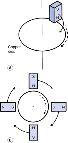
Figure 12.5 An elementary explanation of the induction motor. Rotating the magnets in (A) and (B) will cause the disc to rotate in the same direction because of eddy current formation in the copper.
The disc thus moves in the same direction as the magnet in order to reduce the relative motion between them, so opposing the change producing the current, as required by Lenz’s law. In a frictionless system, the disc would eventually move at the same speed as the magnet so that there would be no relative motion and no induced currents.
A more efficient system is shown in Figure 12.5B where more magnets are used and so a higher magnetic flux linkage is obtained. The copper disc follows the direction of rotation of the magnets for the reasons outlined above. It is not necessary to use permanent magnets since current-carrying solenoids will act as magnets.
The arrangement of the coils for such a motor is shown in Figure 12.6. The current through AB will be 90° out of phase with the current through CD. This produces a magnetic field which appears to rotate at the same frequency as the AC mains supply (50 Hz) and so the disc will also rotate at the same speed (50 revs per second (r.p.s.)=3000 revs per minute (r.p.m.).
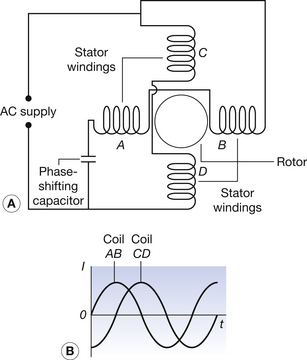
Figure 12.6 (A) Cross-section showing the typical arrangement of stator coils and rotor in an induction motor; (B) current waveform produced by the two pairs of coils because of the influence of the phase-shifting capacitor. Note that the current from one pair of coils is at its maximum when the current from the other pair is at zero.
An AC induction motor is used to cause the rotation of the anode in the rotating anode X-ray tube. The anode assembly is attached to a rotor and these devices are contained within the glass envelope. The stator coils (which produce the rotating magnetic field) are fixed around the outside of this envelope, but the magnetic fields can penetrate the glass and cause the anode to rotate. This will be discussed further in Chapter 30.
12.8 Magnetic deflection of an electron beam
There are a number of situations in radiography where we wish to deflect a beam of electrons, e.g. a beam of electrons is made to scan the face of a television monitor to produce an image or in the bending magnet of a linear accelerator.
Figure 12.7 shows an electron beam travelling in a vacuum and passing through such a magnetic field. It can be seen that the path taken by the electron beam when it passes through the magnetic field is circular since the direction of the deflecting force is always at right angles to the direction of travel. Thus, the electrons are deflected when they pass through the magnetic field. After leaving the magnetic field, the beam again travels in a straight line.
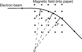
Figure 12.7 The deflection of an electron beam due to a magnetic field. The electrons enter the magnetic field from the left and are deflected on a circular path with 0 as the centre of the circle. The electrons continue on a straight path when they leave the influence of the magnetic field.
The angle of deflection increases as the magnetic flux density increases, so that the direction of the beam can be controlled by varying the magnetic flux density. Thus, by placing magnetic deflection coils on either side of a television monitor we can scan the electron beam in a pattern (known as a raster) across the face of the monitor.
12.9 The motor principle in radiography
The motor principle is relevant to radiography whenever electrical energy is transformed into mechanical energy via magnetic energy. Obvious examples of this include the use of electric motors to drive mobile X-ray machines and the use of motors to tilt or elevate X-ray tables. The motor principle is also utilized in rotating the anode of the rotating anode X-ray tube. Finally, the motor principle is applied to allow scanning of the electron beam in television cameras and monitors.
In this chapter, you should have learnt the following:
• The definition of the motor principle (see Sect. 12.2).
• The factors affecting the direction and magnitude of the force acting on a current-carrying conductor in a magnetic field (see Sect. 12.3).
• A convention to establish the direction of the force on a current-carrying conductor in a magnetic field (see Sect. 12.4).
• The interaction between two electromagnetic fields and how this is applied to two parallel wires (see Sect. 12.5).
• The operation of the DC motor (see Sect. 12.6).
• The operation of the AC induction motor (see Sect. 12.7).
• The factors influencing the magnetic deflection of an electron beam (see Sect. 12.8).
• The applications of the motor principle in radiography (see Sect. 12.9).
Further reading
Ball J.L., Moore A.D., Turner S. Ball and Moore’s Essential Physics for Radiographers, fourth ed. London: Blackwell Scientific, 2008. (Chapter 8)
Ohanian H.C. Principles of Physics. London: W W Norton, 1994. (Chapter 21)
Thompson M.A., Hattaway R.T., Hall J.D., Dowd S.B. Principles of Imaging Science and Protection. London: W B Saunders, 1994. (Chapter 5)