Chapter 29 Exposure and timing circuits
Chapter contents
29.1 Aim
The aim of this chapter is to examine the principles involved in switching the X-ray exposure on and off. It will also consider the physics involved in timing the X-ray exposure.
29.2 Preparation for exposure
Before the X-ray tube can deliver an exposure for a predetermined time interval, it must first be prepared for exposure. This is done during the ‘prep’ stage of the exposure sequence and during this time two major things happen:
1. The appropriate filament of the X-ray tube is raised to its working temperature so that it emits the required number of electrons by thermionic emission (see Sect. 30.7.1) to allow the correct tube current (mA) to flow during the exposure.
2. The anode is made to rotate at the required speed prior to the exposure being made.
If an exposure is made before these processes are completed, there is a risk that the incorrect mA will be delivered or that the target of the anode may be subjected to localized overheating, resulting in damage to the anode. In Sections 13.5 and 13.6, it was shown that selection of a suitable resistance would determine the time taken to charge or discharge a capacitor. This principle is used to provide a delay function prior to the X-ray exposure.
Initiating the prepare sequence causes a switch to open, ‘shorting’ the capacitor to remove any residual charge present. Current flows in the stator circuits and the anode commences to rotate. The switch then closes, which permits a direct current (DC) supply to charge the capacitor through the resistor. When the capacitor is charged, it operates an electronic switch in the exposure circuits, permitting the exposure to commence.
There are two circuit sections responsible for the actual exposure:
29.3 The switching section
The function of the switching section is to connect the high voltage (kVp) to the X-ray tube during the exposure and to disconnect this supply from the tube at the end of the exposure. Such switching commonly occurs between the autotransformer and the high-tension transformer, where it is known as primary switching, or between the high-tension transformer and the X-ray tube, where it is known as secondary switching.
29.3.1 Primary switching
All modem X-ray units make use of solid-state switching. This type of switching has the advantage that there are no moving parts, overcoming the problems experienced with earlier mechanical systems. A simple circuit containing a solid-state switching system is shown in Figure 29.1. Silicon-controlled rectifiers (SCRs), a type of thyristor, are used for this purpose. Two thyristors (connected in inverse parallel) are required to switch an alternating current (AC) as each conducts the half-cycle when that SCR is forward biased. At the end of each half-cycle, each SCR will cease to conduct as the potential difference across it drops to zero and so a voltage pulse must be applied to its gate if it is required to conduct during the next half-cycle.
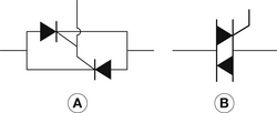
Figure 29.1 Simplified diagram of primary switching using (A) two silicon-controlled rectifiers and (B) a triac.
As an alternative to the SCR, a triac may be used. This device acts as two SCRs connected in inverse parallel and, if pulsed with an alternating supply, will conduct in both phases of the AC cycle. Like the SCR, the device will only conduct when the voltage is not at zero volts and the device has been pulsed.
During the exposure, the timer is simply required to apply a sequence of synchronized pulses to the gate of the device at a time slightly later than the mains zero to switch them back on and ensure their continued conduction. At the end of the exposure, these pulses stop and conduction through the device stops at the end of the next half-cycle. The system allows accuracy of one voltage pulse (i.e. an exposure time of 0.01 second in the case of a two-pulse unit, or 0.002 seconds in the case of a medium-frequency unit; see Ch. 28).
29.3.2 Secondary switching
Solid-state devices such as SCRs cannot withstand the very high voltages present in the high-tension circuit, therefore high-tension valves must be used. In the past, special triode valves were used; modern generators make use of a grid-controlled X-ray tube.
As will be seen in Chapter 30, X-rays are produced when electrons flow from the cathode to the anode of the X-ray tube. These electrons are normally focused onto the target of the tube by a focusing cup, which is at a negative potential approximately equal to that of the filament. If a separate additional negative bias is applied to the focusing cup, then it is possible to make it more negative than the filament. X-ray tubes offering this facility are known as grid-controlled tubes.
If the focusing cup is made about 3 kV more negative than the filament, it will produce a sufficiently large electrostatic field to prevent any electrons from crossing the X-ray tube; this additional negative potential is termed grid bias. At the start of the exposure, this bias is removed, electrons may cross from the cathode to the anode and X-radiation is produced. At the end of the exposure, the high negative bias is re-established on the focusing cup, stopping electron flow. The grid-controlled tube acts as an electronic exposure switch as well as a producer of X-rays.
Secondary switching is also used in capacitor discharge units to control the passage of the charge from the capacitor through the X-ray tube during the exposure time. It was also used in cineradiography and pulsed fluoroscopy, where the system is capable of giving up to 500 exposures per second. In such cases, the switch shown in Figure 29.1 does not exist as the X-ray tube will act as the high-tension switch.
A similar form of grid-controlled switching is used in a number of dental units. In such units, the current through the tube is switched off when the voltage falls below a certain percentage of the peak kV. The principles of the process are shown in Figure 29.2.
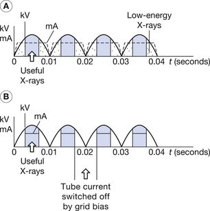
Figure 29.2 The use of a grid-controlled X-ray tube to limit patient dose. (A) Low-energy X-rays are produced which contribute to patient dose but do not contribute to the image. (B) By applying the necessary bias to the cathode, current is prevented from flowing when the tube voltage is below a predetermined limit, preventing production of much of the low-energy radiation.
As we can see from Figure 29.2A, in a conventional X-ray unit, X-rays are produced during each of the voltage pulses but only the X-rays produced at the centre of each voltage pulse (near the peak kV) are of diagnostic value. X-rays produced when the tube voltage is significantly lower than the peak kV have very low photon energies and so will be absorbed by the patient and contribute nothing to the diagnostic image. Preventing production of these low-energy X-rays, we can limit the patient radiation dose and also help to prolong the life of the X-ray tube. This is achieved by applying a strong negative bias to the focusing cup if the tube voltage is below a certain value: no current will flow through the tube and no X-rays are produced. This is shown in Figure 29.2B.
29.4 The timing section
The function of the timing section is to ensure that the appropriate signals are passed to the switching section to allow X-ray production to be switched on and off at the appropriate times. As we can see from Figure 29.3, the resistance is variable; thus, the time taken to charge to a predetermined potential across its plates is determined by the value of the resistance. When this trigger voltage is achieved, a signal is sent to the switching system which terminates the X-ray exposure by stopping current flow through the X-ray tube. If we consider the situation for thyristor switching (see Sect. 29.3.1), then it can be seen that the exposure can be terminated by simply removing the triggering voltage pulses from the gates of the thyristors. Thus, at the end of the next half-cycle, the thyristors will cease to conduct and the exposure will terminate.
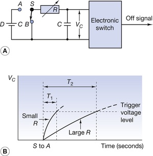
Figure 29.3 Simplified circuit diagram (A) and output graph (B) for a capacitor-controlled timer. Note that when the switch (S) is in position A, the timer is switched off and the capacitor is ‘shorted’, ensuring it cannot retain any electrical charge. To switch on, the switch should be moved to position B. This will allow the capacitor (C) to receive charge through the variable resistor (R).
29.4.1 Time-based timers
If the circuit is arranged in such a way that the capacitor receives charge from a fixed single source (e.g. a rectified supply from the autotransformer), then the time it takes to charge the capacitor will be influenced only by the value of resistance selected by the operator. This is the basis of a time-based timer, i.e. a timer where the operator manually selects the exposure time (along with the kVp and the mA). The X-ray output at a given value of kVp is a function of the tube current (mA) and the exposure time (see Ch. 22). As the time-based timer only controls the exposure time, it cannot compensate for any fluctuations in the tube current that would influence the X-ray output from the tube. This problem is overcome by the mAs timer, which will be discussed in the next section.
29.4.2 The mAs timer
A simplified diagram to show the operating principles of an mAs timer is shown in Figure 29.4. Note that on this occasion the capacitor is charged from two sources, V1 and V2. V1 is a stable source of voltage (e.g. a rectified supply from the autotransformer). The amount of charge which the capacitor receives from V1 is controlled by the variable resistor, R. This supply is connected to the capacitor (C) when the switch moves from position B to position A at the start of the exposure. V2 is a rectified supply from the midpoint of the high-tension transformer, so that the amount of charge from this source is directly related to the amount of charge passing through the X-ray tube (the mAs). This supply is again switched on with the exposure.
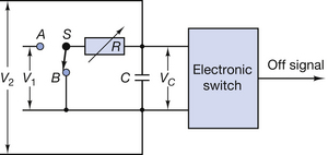
Figure 29.4 Simplified diagram showing the operating principles of an mAs timer. When the timer is switched on, the capacitor (C) receives charge from V1 and V2. For further explanation of the operating principles, see text.
The time taken to charge the capacitor is related to the tube current. A high tube current will result in a short charging time and a low current a longer charging time. When the capacitor is fully charged, an electronic switch terminates the pulses to the exposure switching circuit. The X-ray exposure is then terminated.
These timers can be used on all generators including those where the mAs changes during the exposure such as capacitor discharge and falling load generators.
The mAs timer is manually controlled, with the fundamental problem that the exposure selected depends on the skill and judgement of the operator, who needs to estimate the amount of radiation that will be absorbed by the patient. Ideally the exposure should only deliver sufficient radiation to produce an acceptable image on the image receptor, with the minimum radiation dose to the patient. The principles of this process are shown in Figure 29.5. If R units of radiation leave the X-ray tube and A units are absorbed by the patient, then (R−A) units will strike the imaging device. Thus, ensuring the correct exposure to the film depends on the operator’s skill in judging how much radiation the patient will absorb and selecting the duration of the exposure accordingly.
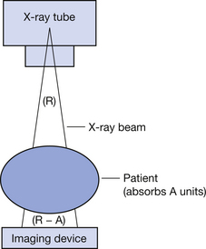
Figure 29.5 Diagram showing the X-ray absorption involved in image production. If R units of radiation leave the X-ray tube and the patient absorbs A units, then (R−A) units of radiation will reach the imaging device.
We will now consider automatic timers, which measure the amount of radiation to a small sample of the recording device and terminate the exposure when this radiation has reached a predetermined value. The operator has control of the kV selected, but has no direct control over the duration of the exposure.
29.4.3 Automatic timers
There are two basic types of automatic timer. The first, the ionization timer, controls the duration of the exposure but permits the operator to select the kV used.
29.4.3.1 Ionization timers
The ionization timer makes use of the fact that X radiation will cause ionization in air. A radiolucent chamber is placed between the patient and the image recording device and as radiation passes though this chamber it ionizes the air within it. The ionized air molecules are attracted to the electrodes in the chamber by a potential difference between them, and as a result, a small electrical current directly proportional to the amount of X radiation flows between the electrodes. This small current is then amplified and used to charge the capacitor (Fig. 29.6). The amount of charge which the capacitor receives from V1 is controlled by the variable resistor, R. V2 is an amplified supply from an ionization chamber (or photocell) which can measure the amount of radiation that has passed through the patient. Assuming that the amount of charge from V1 is determined by the position of the variable resistor, then the remainder of the charge required to raise the potential of the capacitor to the trigger voltage of the switching device must be from the source V2. As this is directly related to the amount of radiation passing through the patient to the imaging device, this will be constant irrespective of the amount of radiation absorbed by the patient. The timer, in this case, terminates the exposure when the correct amount of radiation has passed through the ionization chamber. If the ionization chamber or photocell is positioned under the correct part of the patient, the radiograph will always receive the correct exposure. The resistance of the variable resistor controls the amount of charge required from V2, allowing imaging receptors of differing sensitivities (speeds) to be used.

Figure 29.6 Simplified diagram to show the operating principles of an autotimer. When the timer is switched on, the switch (S) is in position B and so the capacitor (C) receives charge from two sources – V1, a stable voltage supply, and V2, from an ionization chamber.
With the ionization timer, although the timer controls the duration of the exposure, the operator has control over the selection of the exposure variables such as the kV, focus used, the image recording medium and, with some units, the mA used.
29.4.3.2 Anatomically programmed timers
With anatomically programmed timers, the operator selects the exposure by body part and projection from a number of preinstalled options. These options will determine the kV, mA, type of image recording medium, focus to film distance and the ionization chamber to be used to detect the radiation that has passed through the patient.
This range of exposures, which is stored in the memory of a microprocessor, is programmed into the X-ray unit by the manufacturer of the X-ray generator. On installation of the unit, a senior operator programs the final selection of exposure factors for each permitted exposure in the range into the computer memory, which is then ‘locked’ to prevent unauthorized access. A simplified diagram of this type of timer is shown in Figure 29.7. Full details of its operation are beyond the scope of this text.
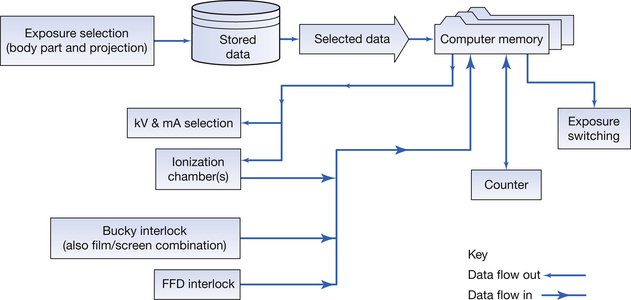
Figure 29.7 Simplified diagram showing the principles of an anatomically programmed timer. FFD, focus to film distance.
On exposure, interlocks are used to check that the X-ray tube is at the correct focus to film distance and the recording medium is in place. The radiation detection device is then selected and exposure commences. When sufficient radiation has passed through the detector, the microprocessor terminates the exposure through the exposure switching circuit.
Since the radiation dose received by the patient and the amount of scattered radiation produced are dependent on the quality and amount of radiation delivered during the exposure, this type of timer ensures that the optimum quantity of radiation delivered and kV are used for each exposure, minimizing both the dose to the patient and the amount of scattered radiation produced.
Autotimers are usually used in conjunction with a guard timer. This is a preset time-based timer (see Sect. 29.4.1) which will terminate the X-ray exposure of the autotimer and isolate the generator from the mains supply. The guard timer must be reset by a service engineer before the generator can be reused.
In this chapter, you should have learnt the following:
• The role of the circuits which prepare the X-ray unit for exposure (see Sect. 29.2).
• The role of the switching section in the X-ray generator (see Sect. 29.3).
• The function and operation of primary exposure switching (see Sect. 29.3.1).
• The function and operation of secondary exposure switching using a grid-controlled X-ray tube (see Sect. 29.3.2).
• The principles of the timing section of the X-ray generator (see Sect. 29.4).
• The principles and mode of operation of time-based timers (see Sect. 29.4.1).
• The principles and mode of operation of the mAs-based timer (see Sect. 29.4.2).
• The principles and mode of operation of autotimers utilizing ionization chambers (see Sect. 29.4.3.1).
• The principles and an outline of the operation of the anatomically programmed timer (see Sect. 29.4.3.2).
Further reading
Carter P.H. Chesney’s Equipment for Student Operators, fourth ed. London: Blackwell, 1994. (Chapter 4)
Curry T.S.III, Downey J.E., Murry R.C.Jr. Christensen’s Physics of Diagnostic Radiography, fourth ed. London: Lee & Febiger, 1990. (Chapter 2)
Webb S., editor. The Physics of Medical Imaging, second ed, Bristol: Institute of Physics, 2000.