Chapter 13 Capacitors
Chapter contents
13.1 Aim 77
13.2 Introduction 77
13.3 Electrical capacity (capacitance) 77
13.4 Capacitance of a parallel-plate capacitor 78
13.5 Charging a capacitor through a resistor from a DC supply 80
13.6 Discharging a capacitor through a resistor 80
13.7 The time-constant for a capacitor resistor circuit 80
13.8 Capacitors and alternating current 81
13.9 Capacitors in radiography 81
Further reading 82
13.1 Aim
The aim of this chapter is to introduce the subject of capacitors and capacitance. It then considers the factors that influence the performance of a capacitor, how capacitors can be linked to other components and how capacitors are used in radiography.
13.2 Introduction
In Chapter 11, we considered the influence of a capacitor on the current and voltage in an alternating current (AC) circuit. We were able to do this without an understanding of the construction or the operation of a capacitor. There are circumstances where capacitors are used and where we need to understand either the construction and/or the operation of the capacitor to understand its function within the piece of equipment. This chapter deals with the physics of the capacitor, which is a device for storing electrical charge. It has many applications in radiography as it can be charged and discharged quickly unlike a battery.
13.3 Electrical capacity (capacitance)
We have previously shown in Chapter 6 that when a body has a net positive or negative charge it also possesses an electrical potential, because work must be done in moving a unit positive charge from infinity to the body. This potential is positive if the charge on the body is positive and negative if the charge on the body is negative.
The electrical capacity or capacitance of the body is the relationship between the charge put on the body and its potential:
13.3.1 Definitions and unit of capacitance (farad)
The definition of capacitance varies slightly depending on the type of body holding the charge. When a body consists of one surface only (e.g. a sphere) the following definition applies:
If the body consists of two surfaces close together, we must consider the potential differences between the surfaces rather than the potential on each. This leads to the following alternative definition of capacitance:
The capacitance of a body is the ratio of the total charge of one sign on the body to the potential difference between its surfaces.
It is important to remember that capacitance involves both charge and potential and so it is not correct to think of capacitance as the ‘amount of charge a body can hold’ unless we add the phrase ‘per unit potential difference’. The International System of Units (SI) unit of capacitance is the farad and may be defined as:
An electrical system has a capacitance of 1 farad if a charge of 1 coulomb held by the body results in a potential (or potential difference) of 1 volt.
Thus, Equation 13.1 may be expressed as:
An alternative definition of capacitance, and one that is often more useful in radiography, is to consider capacitance in terms of the change of charge divided by the corresponding change in potential.
If a capacitor starts with a charge Q and a potential difference, then by definition:

If an extra charge, ΔQ is added to the plates and an extra potential difference ΔV, results, then:

i.e. capacitance is the total charge divided by the total potential difference.
By cross-multiplying the above equation, we get:

However, we can say from Equation A that:

Thus, Equation B can be rewritten:

This gives the alternative definition of capacitance, which can be used in radiography for calculations involving capacitor discharge circuits, etc.
For practical purposes, the farad (F) is rather a large unit in which to measure capacitance and so it is more commonly expressed in units of microfarads (μF) or picofarads (pF), where:


13.4 Capacitance of a parallel-plate capacitor
Figure 13.1 (see page 79) shows a parallel-plate capacitor with two plates of equal area, separated by a distance, d. The plates are made of electrical conductors so that charge may flow in and out of each plate. If the capacitor is charged– e.g. by connecting it across a battery as shown – then a charge of +Q will exist on one plate and a charge of −Q on the other. If the battery is disconnected, the charge will continue to be stored on the plates of the capacitor as the positive charge on one plate attracts the negative charge on the other. This is why a capacitor is often described as a device for storing charge. (A large capacitor will retain this charge for a long period of time after it has been disconnected from the source of electromotive force (EMF). For this reason, it should be treated with extreme care as severe electric shock may result from touching the plates or the electrical connections to the capacitor.)
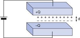
When the capacitor is fully charged, a potential difference equal to that of the battery exists across the plates. Thus, the capacitance of the parallel-plate capacitor is given by the equation C=Q/V where Q is the charge of one sign on one of the plates and V is the potential difference between the plates.
Certain characteristics of the capacitor will affect its capacitance and these will now be considered.
13.4.1 Area of the plates
If the area of the plates (A) is increased, then more charge will be able to flow onto the plates from the battery until the charge per unit area is the same as before. It can be seen that if the area of the plates is doubled then the amount of charge which they will hold, to give the same charge per unit area, will also be doubled. In this situation, V remains unaltered, as it is the same as the potential difference from the battery and Q∝A. Since C=Q/V, we can say that:

Note: If the plates are not directly opposite each other, then the area taken for this calculation of capacitance is the effective area, i.e. the area of the plates which are in direct opposition to each other.
13.4.2 Separation of the plates
If the rest of the capacitor remains unaltered but the plates are brought closer together, then the charges on opposite plates will experience a greater force of attraction so that the battery will be able to ‘push’ more charge onto the plates. Once again, V is constant, but Q∝ l/d. Since C=Q/V we can then say that:

13.4.3 Dielectric constant of material between the plates
A material with a high dielectric constant is an insulator where it is relatively easy to induce a charge on its surface (see Sect. 6.7.2). The effect of placing such a material between the plates of a charged capacitor is shown in Figure 13.2. The close proximity of the charges on the plates and on the dielectric results in some ‘cancellation’ of charges (as shown ringed in Figure 13.2B). If this capacitor is now reconnected to the battery, it will be seen that more charge will flow onto the capacitor. Thus, once again, V is the same value but Q has increased and so the capacitance of the capacitor increases with the dielectric constant (K), so we can say:
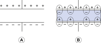
Figure 13.2 (A) Parallel-plate capacitor with no dielectric between the plates. (B) Capacitor after a dielectric has been introduced between the plates. The induction of charge in the dielectric ‘cancels’ some of the charges stored on the plates (shown as ringed charges). This means that the battery can now place more charge on the plates of the capacitor.

This leads to the definition of the dielectric constant.
The dielectric constant of a material is the ratio of the capacitance of the capacitor with the dielectric to the capacitance without the dielectric (i.e. with a vacuum between the plates of the capacitor).
From this, it can be seen that the dielectric constant of a vacuum is unity (1). If we take the above three components together we get:

By the addition of a constant of proportionality (ε0), this now becomes:

13.5 Charging a capacitor through a resistor from a DC supply
Consider the situation illustrated in Figure 13.3A. Here a battery is connected across a resistor R and a capacitor C in series. When the switch S1 is closed, electrons will flow onto one of the plates of the capacitor and away from the other plate, as shown in the illustration. The potential difference across the capacitor, VC, therefore increases due to the charge on the plates. However, it does not increase indefinitely, but settles to a value that is the same as (but of opposite polarity) to that of the battery. To understand why this is the case, consider the forces acting on an electron at the point P. When the switch S1 is initially closed, a complete circuit is made and, due to the EMF from the battery, a force is exerted on the electron, pushing it towards the capacitor. However, as soon as the plate starts to build up electric charge, it in turn exerts a force on the electron at P in the opposite direction, which slows down the rate of flow of charge onto the plate. Eventually the two opposing forces on the electron will become equal and there is no further flow of electrons through the circuit. At this stage, the potential across the capacitor is equal and opposite to the potential across the battery. This situation is shown in Figure 13.3B where there is an initial rapid rise in potential (VC) when S1 is closed, but this slows down and approaches VB relatively slowly.
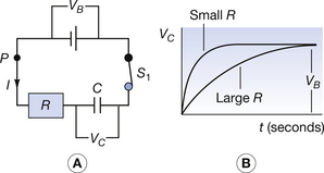
Figure 13.3 Charging a capacitor. (A) The circuit for charging a capacitor (C) though a resistor (R). (B) Graph showing the effect of using different resistors on the rate of charge.
The effect of the resistance R is to limit the electron flow rate so that VB is approached more slowly for large values of R than for small values of R, as shown in Figure 13.3B.
From this, it can be seen that a capacitor does not pass direct current (DC), for, after the short time required to charge the capacitor, all further electron movement (flow of current) ceases.
13.6 Discharging a capacitor through a resistor
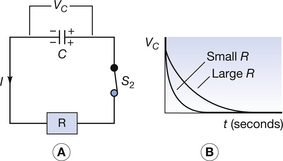
InFigure 13.4A, a charged capacitor with a potential VC across its plates is allowed to discharge through the resistor R when the switch S2 is closed. When this happens, electrons travel from the negative plate of the capacitor, through the resistor R and onto the positive plate and the charge on the plates and the potential between them (VC) is reduced. The reduction in VC means that there will be less ‘push’ on the electrons in the next time interval (see Sect. 13.7) resulting in a smaller drop in VC. This situation continues, as shown in Figure 13.4B, until the capacitor is discharged and the potential difference is zero. Again, the effect of R is to slow down the current and so the rate of fall of VC.
13.7 The time-constant for a capacitor resistor circuit
This is an example of the exponential law (see Ch. 20) and this can be seen by comparing the graphs in Figures 13.3 and 13.4 with those in Chapter 20. The potential difference between the plates of a discharging capacitor can be calculated from the equation:

where V0 is the potential difference between the plates before discharging the capacitor, t is the time of the discharge (in seconds), R is the resistance in ohms and C is the capacitance in farads. The quantity RC is called the time-constant. After a discharge time of 1 time-constant, the potential difference across a discharging capacitor has dropped to 1/e of its initial value, i.e. 0.37 of its initial value. If the original potential difference is 6 V, the value after 1 time-constant is 0.37×6=2.2 V. After 2 time-constants, the value will be reduced to a further 0.37, i.e. 0.37×2.2=0.8 V. Note that this is very similar to the concept of half-life discussed in Chapter 20 since both are examples of exponential decay.
If we consider a capacitor being charged, then the equation for the potential across it is:
V0 is the charging source EMF. Again, RC is the time-constant. After 1 time-constant the potential across the capacitor will be 1−1/e, which is 0.63. Thus, for a charging capacitor, after 1 time-constant the potential across its plates will be 0.63 of its final value (the final value will be the same as the charging source EMF).
13.8 Capacitors and alternating current
We have already shown in this chapter that a capacitor will eventually possess the same potential difference as the electrical supply connected across it. If the potential difference of supply is changed, a new equilibrium will become established where, once again, the two values of potential difference are equal. Thus, if an alternating supply is connected across the capacitor, the potential of the capacitor ‘follows’ the potential of the supply. Thus, it can be said that a capacitor passes AC since the potential difference (PD) on the capacitor changes continually, in sympathy with the PD of the supply.
As we have already seen in Chapter 11, when a capacitor is introduced to an AC circuit, the PD across the plates lags 90° behind the current. The effect of this phase difference must be taken into account for many of the uses of capacitors in AC circuits.
13.9 Capacitors in radiography
The ability to store electrical charge on the plates of a capacitor has important practical consequences in radiography. Some of the practical uses of capacitors in radiography are the following:
There is insufficient space in this text to describe all these uses in detail and so only a brief overview of each will be given. The applications of capacitors in electronic timers will be studied in more detail in Chapter 29.
13.9.1 Capacitor discharge mobile units
Figure 13.5 shows the basic principles of such a circuit. When an exposure is made on a mains-dependent mobile unit, a large current (around 30 A) is drawn from the mains during the exposure. This large current can cause large power losses in the mains cables (remember, P=I2R). The capacitor discharge mobile works on the principle that a small current is drawn from the mains to charge a capacitor before the X-ray exposure, and this capacitor is allowed to discharge through the X-ray tube during the exposure. Since the electrical energy to the tube comes from the capacitor, no significant stress is applied to the mains supply during the exposure.
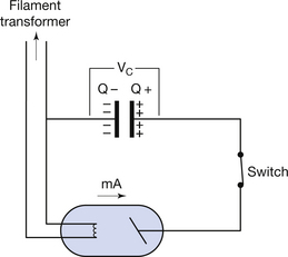
Figure 13.5 shows the basic principles of such a circuit. With the switch open, the capacitor is initially charged until the required potential (VC is the same value as the kV which will be applied to the tube) is established across its plates. On closing the switch, electrons flow from the negative plate of the capacitor to the positive plate via the X-ray tube. This means that a potential difference (kV) is applied across the tube and charge (mAs) flows through it, comprising a radiographic exposure. At the end of the exposure, the switch is opened.
As a result of the exposure, the capacitor loses some of the charge on its plates and so the potential difference at the end of the exposure is less than the initial potential difference. However, when long exposures are made, there is a significant drop in the energy of the X-ray beam during the exposure as the energy stored in the capacitor falls. This must be taken into account when selecting exposure factors on such a unit.
13.9.2 Voltage smoothing
When an alternating voltage is full-wave rectified (see Ch. 28) and applied to a component, the voltage waveform will be as shown in Figure 13.6A. Thus, during each half-cycle a potential difference ranging from the peak voltage to 0 V is applied across the component. This difference between the peak and the trough in the voltage is known as the voltage ripple. In this case, the ripple is 100%. There are some situations where it is beneficial to reduce this ripple. This is done by connecting a capacitor (or sometimes two capacitors) in parallel with the component so that the voltage supply is smoothed by the capacitor before it is applied to the component. The result of capacitor smoothing of the voltage is shown in Figure 13.6B. The broken line shows the voltage waveform from the rectification circuit. Initially the capacitor charges so that the potential between its plates is the same as the peak potential from the rectification circuit. As this supply voltage drops, the capacitor discharges through the component so that the potential difference between its plates slowly drops. When this potential has dropped by a small amount, the potential from the supply ‘catches up’ with it (point A on the graph) and charge will once again flow on to the capacitor so that it reaches its peak potential difference at the same time as the supply voltage.
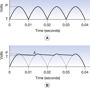
Figure 13.6 (A) Voltage waveform from a single-phase transformer after it has been rectified. (B) The same waveform after capacitor smoothing, where P represents the peak and T the trough. The difference between the peak and the trough is known as the ripple. Note how capacitor smoothing reduces the voltage ripple.
This application is important in medium-frequency rectification systems as, by using capacitors that are suitably matched to the components being supplied with electrical energy, the voltage ripple can be reduced to less than 1%.
13.9.3 Phase splitting for AC induction motors
When a capacitor is introduced into an AC supply, it causes a phase shift between the current and voltage. This is utilized in the AC induction motor. The detail of the operation of this motor is given in Section 12.7. The role of the capacitor is to produce a current in one pair of coils that is 90° out of phase with the current in the other pair. This produces a magnetic field, which appears to rotate at the same speed as the mains frequency and so produces rotation of the motor rotor.
13.9.4 Electronic timers
The ability to store electrical charge on the plates of a capacitor has important practical consequences in radiography. These will be discussed in Chapter 29.
In this chapter, you should have learnt the following:
• The meaning of the term electrical capacitance (see Sect. 13.3).
• The definition of the farad – the unit of capacitance (see Sect. 13.3).
• The factors affecting the capacitance of a parallel-plate capacitor (see Sect. 13.4).
• The definition of the term dielectric constant (see Sect. 13.4).
• The consequences of charging a capacitor from a DC source through a resistor (see Sect. 13.5).
• The definition and the uses of the time-constant for a capacitor/resistor circuit (see Sect. 13.7).
• The effect on the voltage and the current in an AC circuit when a capacitor is introduced to the circuit (see Sect. 13.8).
• Some of the applications of capacitors in radiography (see Sect. 13.9).