Contemporary Implant Dentistry
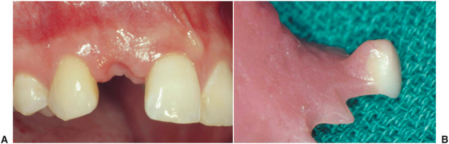
The dental professional must use considerable clinical skill to help patients cope with the effects of partial or complete edentulism. Dental problems that were historically the most difficult can be solved today with the assistance of dental implants. Completely edentulous patients now enjoy the security and function of fixed restorations (Fig. 14-1). Patients missing a posterior abutment, who would ordinarily require a distal extension removable partial denture, may now enjoy the benefits of a fixed restoration with dental implants (Fig. 14-2). Trauma victims who are missing teeth and bone can be successfully rehabilitated with fixed restorations (Fig. 14-3).
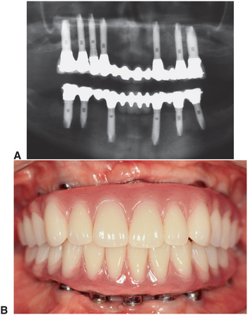
FIGURE 14-1 A, Radiograph showing fixed restorations supported by seven implants in the maxilla and six in the mandible. B, Metal-resin restorations are the treatment of choice for edentulous patients with moderate bone resorption. (Rosenstiel SF, Land MF, Fujimoto J: Contemporary fixed prosthodontics, ed 4, St Louis, 2006, Mosby.)
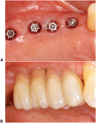
FIGURE 14-2 Implant-supported fixed prosthesis. Four dental implants (A) supporting a fixed dental prosthesis (B). (Rosenstiel SF, Land MF, Fujimoto J: Contemporary fixed prosthodontics, ed 4, St Louis, 2006, Mosby.)
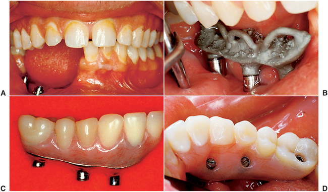
FIGURE 14-3 A, Large mandibular defect created by a shotgun wound. B, Metal substructure of a metal-resin prosthesis tied onto three implants in this defect. C, Denture resin can more effectively recreate the soft tissue color and contours in the completed restoration than dental porcelain. D, Metal-resin restorations over the defect. (Rosenstiel SF, Land MF, Fujimoto J: Contemporary fixed prosthodontics, ed 4, St Louis, 2006, Mosby.)
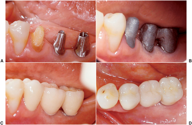
Even the patient missing only a single tooth can receive a restoration more analogous to the missing natural tooth (Fig. 14-4). Likewise, a patient with adequate alveolar bone can receive a complete fixed implant rehabilitation (Fig. 14-5). These examples illustrate advantageous and predictable alternatives to edentulism that are becoming the standard of care within the dental community.
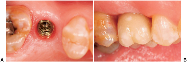
FIGURE 14-4 A, Single-tooth implant with an internal antirotational feature. B, Implant crown replacing a single missing tooth (cement retained). (Rosenstiel SF, Land MF, Fujimoto J: Contemporary fixed prosthodontics, ed 4, St Louis, 2006, Mosby.)

FIGURE 14-5 A to D, A metal-ceramic implant restoration may be indicated if adequate bone and soft tissue contours are available. (Rosenstiel SF, Land MF, Fujimoto J: Contemporary fixed prosthodontics, ed 4, St Louis, 2006, Mosby.)
The dental profession has not always had a positive opinion of dental implants. Implants had their beginnings around the middle of the twentieth century. Early types of dental implants came into relatively common use during the 1960s because of patient demand, although little or no scientifically sound research had been done to characterize implant success rates.
In a May 1982 conference held in Toronto, the North American dental profession was introduced to a body of scientific literature on Swedish research into the bone-to-implant interface—a concept called osseointegration. This new concept is based on atraumatic implant placement and delayed implant loading. These factors contribute to a remarkably higher degree of implant predictably than was previously possible. The Swedish research team led by P.I. Branemark reported high success in the mandible for more than 15 years. The knowledge gained from the experience of the Swedish team was used in the development of other systems currently available on the market. Today the American Dental Association has also approved many other systems.
In 1988 a National Institutes of Health consensus conference was held in Washington, D.C. This conference evaluated the long-term effectiveness of dental implants and established indications and contraindications for the various types of dental implants. Stringent criteria for success were proposed and have gained general acceptance (Box 14-1). By these criteria, success rates of 85% at the end of a 5-year observation period and 80% at the end of a 10-year period are minimal levels for success.
BIOLOGIC CONSIDERATIONS FOR OSSEOINTEGRATION
The recent success of dental implants relates directly to the discovery of methods to maximize the amount of bone and implant contact. Osseointegration is a histologic definition meaning “a direct connection between living bone and load-bearing endosseous implant at the light microscopic level.” Four main factors are required to achieve a successful osseointegrated bone-to-implant interface: (1) a biocompatible material, (2) an implant precisely adapted to the prepared bony site, (3) atraumatic surgery to minimize tissue damage, and (4) an immobile, undisturbed healing phase. A biocompatible material is necessary to promote healing without a foreign-body rejection reaction by the host tissue. If biocompatible materials are not used, the body attempts to isolate the foreign-body implant material by surrounding it with granulation and then connective tissue. It has been demonstrated that titanium and certain calcium-phosphate ceramics are biologically inert.
The size of the gap between the implant and the bone immediately after implant placement is critical to achieving osseointegration. The gap size can be controlled primarily by the preparation of a precise cylindrically shaped surgical bed into which the implant is placed. Precision instrumentation and a technically sound surgical procedure help minimize the distance between the implant and host bone.
Atraumatic surgery is required to allow minimal mechanical and thermal injury to occur. Sharp, high-quality burs that are run at low speed by high-torque drills are essential to precise atraumatic implant site preparation. Copious irrigation by internal or external methods must keep the bone temperatures to levels below 56° C, which is the level beyond which irreversible bone damage occurs. It has been shown that bone tissue damage occurs when the bone temperature reaches 47° C for more than 1 minute. If the temperature rises, alkaline phosphatase within the bone is denatured, this prevents alkaline calcium synthesis. If the gap between the implant and the bone can be minimized and surgery is atraumatic, embryonic bone will be laid down rapidly between the implant and the bone and will then mature into the lamellar load-bearing bone (Fig. 14-6).
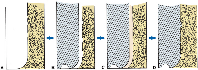
FIGURE 14-6 A, Implant site prepared in bone using irrigation to keep temperatures below 47° C to prevent cell damage and death in area. B, Precisely machined implant placed in site. Gap between implant and bone should be much less than 1 mm. C, If gap between implant and bone is small enough, embryonic bone will rapidly bridge gap. D, If implant is left undisturbed during healing phase, embryonic bone on the implant surface will mature to lamellar load-bearing bone.
Implant immobility during the healing phase is affected by the precision of site preparation, bone quality, and quantity in the vertical and buccal-lingual dimensions. Areas of the jaws that have a high percentage of cortical bone, such as the anterior mandible, are more likely to anchor the implant successfully. Areas of the jaws with a high percentage of cancellous bone make initial stability of the implant more difficult to achieve. If the superior and inferior cortical plates can be engaged by the implant, this also is advantageous for initial implant stability (Fig. 14-7). This is frequently possible in the anterior mandible and the maxilla; however, the inferior alveolar canal prevents this from occurring in the posterior mandible. Regardless of the anatomy in the area of implant placement, it is crucial to obtain primary stabilization for successful osseointegration. Once the implant is placed, a healing cover is inserted and the mucosa is sutured over the implant. In some cases the implant is not covered and a short healing screw protrudes through the gingival. In all cases the implant is protected from occlusal forces.
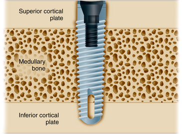
FIGURE 14-7 Whenever possible, implants should engage two cortical plates of bone. (Rosenstiel SF, Land MF, Fujimoto J: Contemporary fixed prosthodontics, ed 4, St Louis, 2006, Mosby.)
Once the initial stability of the implant has been achieved, it must be maintained throughout the healing phase. Should the patient desire to continue to wear the removable prosthesis during the healing period, it is important that a soft liner be placed in the removable denture to further decrease load transfer to the implant. The bone in the mandible is generally denser than the bone in the maxilla with a higher ratio of cortical to cancellous bone. Because the maxilla is primarily cancellous bone and the cortical bone is much thinner than in the mandible, osseointegration requires a longer healing period.
The achievement of successful osseointegration is first assessed at the second-stage surgery when the implant is uncovered, the healing cover is removed, and a prosthetic abutment is inserted. Once the abutment is attached to the implant body, the surgeon should carefully check for any signs of clinically detectable mobility. An immobile implant at this stage usually indicates successful osseointegration. Detectable mobility at this stage indicates that fibrous connective tissue has encapsulated the implant, in which case the implant should be removed at that time. The failed site is allowed to heal, and another implant can be placed at a later time. Once a successful osseointegrated bone-to-implant interface has been achieved, masticatory function at least equal that of natural dentition is generally possible.
The major mechanisms for the destruction of osseointegration are similar to those of natural teeth. Disease activity in the periimplant soft tissue environment and biomechanical overload of the individual implant are the two factors most commonly associated with the potential breakdown of osseointegration.
Soft Tissue–to–Implant Interface
The successful dental implant should have an unbroken, perimucosal seal between the soft tissue and the implant abutment surface. To maintain the integrity of this seal, the patient must maintain a high level of oral hygiene specific to dental implants. Clinicians, dental hygienists, and patients must understand and appreciate the necessity for a comprehensive implant maintenance program, including regularly scheduled recall visits. In the natural dentition the junctional epithelium provides a seal at the base of the gingival sulcus against the penetration of chemical and bacterial substances. It has been demonstrated that epithelial cells attach to the surface of titanium in much the same manner in which the epithelial cells attach to the surface of the natural tooth, that is, through a basal lamina and by the formation of hemidesmosomes. The connection differs from that occurring with natural teeth at the connective tissue attachment level. In the natural dentition, Sharpey’s fibers extend from the bundle bone of the lamina dura and insert into the cementum of the tooth root surface. Because no cementum or fiber insertion is found on the surface of an endosseous implant, the epithelial surface attachment is all-important. If this seal is lost, the periodontal pocket can extend directly to the osseous structures. Therefore, if the seal breaks down or is not present, the area of the bone-implant interface is subject to periimplant gingival disease.
Although the abutment–to–junctional epithelium attachment is not mechanically strong, it is adequate to resist bacterial invasion with the assistance of adequate home care. When implants are stable and they have a highly polished titanium collar transversing the tissue, gingival and periimplant health is relatively easy to maintain. The lack of a definitive gingival connective tissue attachment appears to be less of a problem in osseointegrated implants than it was in implants with fibrous connective tissue attachments. Because osseointegrated implants have a different relationship between the implant and bone, there appears to be different mechanisms working against inflammation caused by bacteria and their by-products. The pathogenicity of the bacteria seems to be particularly diminished in the completely edentulous patient restored with dental implants. Inflammation around the natural dentition in the partially edentulous patient may contribute to a slightly higher incidence of periimplant disease in these patients.
Biomechanical Factors Affecting Long-Term Implant Success
Bone resorption around dental implants can be caused by premature loading or repeated overloading. Vertical or angular bone loss is usually characteristic of bone resorption caused by occlusal trauma. When pressure from traumatic occlusion is concentrated, bone resorption occurs by osteoclastic activity. In the natural dentition, bone redeposition would typically occur once the severe stress concentration is reduced or eliminated. However, in the osseointegrated implant system, after bone resorbs, it usually does not reform. Because dental implants can resist forces directed primarily in the long axis of the implant more effectively than they can resist lateral forces, lateral forces on implants should be minimized. Lateral forces in the posterior part of the mouth have higher impact and are more destructive than lateral forces in the anterior part of the mouth. When lateral forces cannot be completely eliminated from the implant prosthesis, efforts should be made to distribute the lateral forces equally over as many teeth and implants as possible.
Divergent implant placement (varying the angle of placement of adjacent implants) can also improve the vectors through which force is transferred to the bone-to-implant interface. Such force could potentially exceed the threshold for bone resorption. Inadequate implant distribution, which leads to excessive cantilevers, can also potentially overload the system (Fig. 14-8).
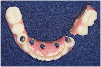
FIGURE 14-8 Cantilever fracture of a metal-resin prosthesis. (Rosenstiel SF, Land MF, Fujimoto J: Contemporary fixed prosthodontics, ed 4, St Louis, 2006, Mosby.)
Connecting a single osseointegrated implant to one natural tooth with a fixed partial denture may effectively create an excessive cantilever situation, as well. Because of the relative immobility of the osseointegrated implant compared with the functional mobility of a natural tooth when loads are applied to the bridge, the tooth can move within the limits of its periodontal ligament. This can create stresses at the neck of the implant up to 2 times the applied load on the prosthesis (Fig. 14-9). Potential problems with this type of restoration are described in Box 14-2. Therefore, freestanding implant restorations not attached to any natural teeth should be planned whenever possible.
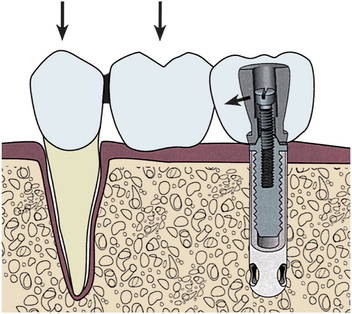
FIGURE 14-9 When a single implant is attached to a natural tooth, biting forces on the natural tooth and pontic cause stress to be concentrated at the superior portion of the implant. (Rosenstiel SF, Land MF, Fujimoto J: Contemporary fixed prosthodontics, ed 4, St Louis, 2006, Mosby.)
Additionally, pathogenic forces can be placed on implants by nonpassively fitting frameworks. If screws are tightened to close gaps between the abutment and the nonpassive framework, compressive force is placed on the interfacial bone. Excessive force of this nature can lead to implant failure (Fig. 14-10).
PREOPERATIVE MEDICAL EVALUATION OF IMPLANT PATIENT
As with any surgery, the implant patient must be assessed preoperatively to evaluate the patient’s ability to tolerate the proposed procedure. The predictable risks and the expected benefits should be weighed for each patient because surgical placement of dental implants may be associated with certain risks.
Of concern are the immediate surgical and anesthetic risks associated with implant placement. Because implant placement is a relatively atraumatic procedure, little immediate surgical risk exists. Absolute contraindications to implant placement based on immediate surgical and anesthetic risks are limited primarily to patients who are acutely ill, those with uncontrolled metabolic disease, and pregnant patients. These contraindications are applicable to virtually all elective surgical procedures. These conditions are also generally limited in duration; once the illness resolves, the pregnancy is over, or the metabolic disorder is controlled, the patient may become a good implant candidate. Relative contraindications may also exist. Many implant patients are elderly and have preexisting chronic systemic medical conditions such as diabetes mellitus that may effect long-term success of implant treatment. Although the presence of a chronic medical condition is rarely a contraindication to surgical placement of implants, each patient must be evaluated for anesthesia and surgery in light of the preexisting disease process, as discussed in Chapter 1.
Local and systemic conditions that threaten long-term retention of the implants must be evaluated. Implants may be contraindicated in patients with abnormal bone metabolism, poor oral hygiene, and previous radiation to the implant site or who are smokers. Smoking has been conclusively linked with increased implant failure. Although smoking is not an absolute contraindication, patients who smoke should be counseled on cessation and informed of the increased risk of failure.
Although osteoporosis is prevalent in the geriatric female population, these patients show no documented decrease in the success of implants. Bisphosphonate medications are often used orally for control of osteoporosis. These medications may also be used via an intravenous route as adjunctive therapy for certain malignancies. Although the impact of oral therapy on implant bone healing has not been established, it is clear that previous intravenous bisphosphonate therapy is an absolute contraindication to implant surgery. These patients have high risk of refractory bone necrosis when even minor surgery is performed (see Chapter 18). Other metabolic bone disorders, including osteopetrosis, fibrous dysplasia, chronic diffuse sclerosing osteomyelitis, and florid osseous dysplasia, may contraindicate implant placement.
Most patients who present for implant placement became edentulous from caries and periodontal disease resulting from poor oral hygiene. Suspicion that inadequate hygiene is likely to continue is a relative contraindication to implant placement. Patients must be motivated and educated in oral hygienic techniques as part of their preparation for implants. Some patients may not be able to improve their hygiene, such as those suffering from paralysis of the arms, debilitating arthritis, cerebral palsy, and severe mental retardation. Implants are contraindicated in these patients, unless caregivers will provide adequate hygiene. A summary of contraindications to implant placement is presented in Box 14-3.
BOX 14-3 Contraindications to Implant Placement
 Uncontrolled metabolic disease
Tumoricidal radiation including the implant site*
*Perioperative hyperbaric therapy may allow implant placement.
SURGICAL PHASE: TREATMENT PLANNING
Clinical and radiographic evaluation of the planned implant site is essential to treatment planning, to determine whether adequate bone exists and to evaluate the proximity of anatomic structures that may interfere with implant placement.
Evaluation of Implant Site
Evaluation of the planned site begins with a thorough clinical examination. Visual inspection and palpation allow the detection of movable redundant tissue, narrow bony ridges, and sharp underlying ridges and undercuts that may limit implant placement. Clinical inspection alone may not be adequate if the thick overlying soft tissue is dense, immobile, fibrous tissue (Fig. 14-11).
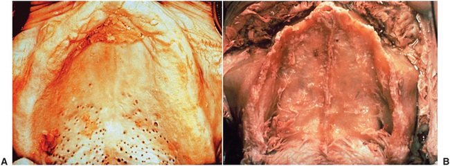
FIGURE 14-11 A, Cadaver specimen of edentulous maxilla that appears to have adequately wide ridge. B, Same specimen with soft tissue removed. Very thin and knife edge ridge is present, which was not evident from clinical examination.
Radiographic evaluation is also necessary, with the best initial film being a panoramic radiograph. Because variations in magnification may occur (Fig. 14-12), a small radiopaque reference object of known size placed at the area of the proposed implant placement allows correction for any magnification. A ball bearing placed in wax on a denture base plate or within polyvinyl siloxane putty adapted to the ridge works well (Fig. 14-13). The known size of the metallic ball bearing can be compared to the size seen on the radiograph, and the degree of magnification can be determined precisely.
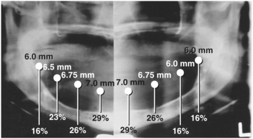
FIGURE 14-12 Panoramic radiograph with standard-sized steel ball bearings placed along ridge. Magnification varies from site to site.
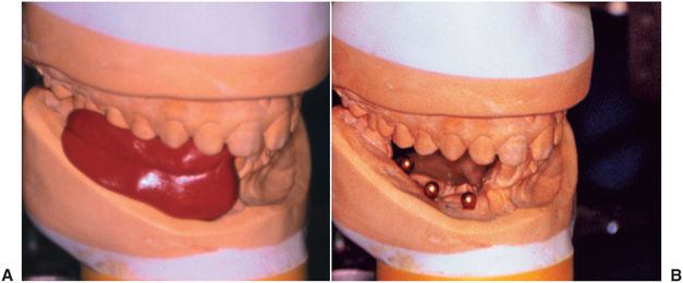
FIGURE 14-13 A, Steel ball bearings of known diameter are placed on cast at points at which implants are to be placed. B, Polyvinyl siloxane impression material is placed over bearings. This can be carried to mouth and used to produce a radiograph with ball bearings as a standard to calculate effect of magnification.
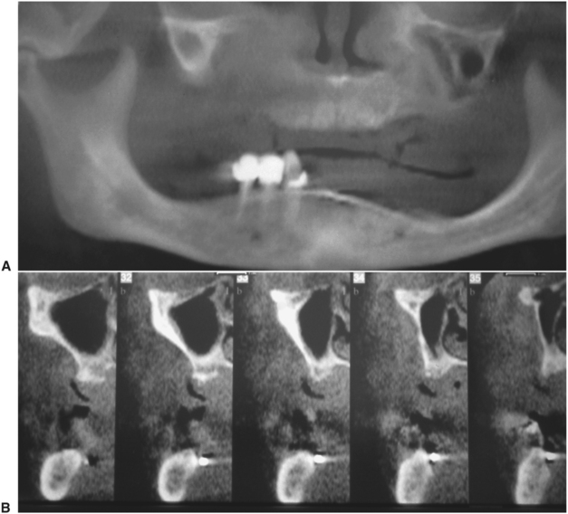
Bone width is not revealed on panoramic films but can be evaluated in the anterior maxilla and mandible with a lateral cephalometric film. Width of the posterior mandible and maxilla are primarily determined by clinical examination. Specialized computed tomography scans are useful to determine the location of the inferior alveolar canal and maxillary sinus and to evaluate ridge form (Fig. 14-14). Once only available in limited settings, cone-beam computed tomography has become more commonly available in many dental offices. Such equipment may become the standard of care in the future. For the present time, these imaging devices should be viewed as adjunctive tools because their routine use is not required and has not been demonstrated to improve outcome or decrease morbidity.
Bone Height, Width, and Anatomic Limitations
Bone quality and quantity are important considerations. In general, more cortical bone and denser cancellous bone (i.e., anterior mandible) is associated with higher implant success compared with thinner cortical bone and loose cancellous marrow (i.e., posterior maxilla). Bone quality has been classified as types I to IV (Fig. 14-15). In type I to III bone, implant success, regardless of length, is predictably high. However, in type IV bone, short implants (<10 mm) have significantly higher failure rates.
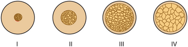
FIGURE 14-15 Bone types based on quantity of cortical bone and density of cancellous marrow. (Misch CE: Contemporary implant dentistry, ed 3, St Louis, 2008, Mosby.)
To maximize the chance for success, there must be adequate bone width to allow 1 mm of bone on the lingual aspect and 1 mm on the facial aspect of the implant. There should also be adequate space between the implants. The minimal distance between implants varies slightly among implant systems but is generally accepted as 3 mm. This minimal space is necessary to ensure bone viability between the implants and to allow adequate oral hygiene once the restorative dentistry is complete.
Specific limitations as a result of anatomic variations between different areas of the jaws must also be considered. Implant length, diameter, proximity to adjacent structures, and time required to achieve integration varies in areas within the jaws. The anterior maxilla, posterior maxilla, anterior mandible, and posterior mandible each require special consideration when placing implants. Some common guidelines for implant placement are summarized in Table 14-1.
TABLE 14-1
Anatomic Limitations to Implant Placement
| Structure | Minimum Required Distance Between Implant and Indicated Structure |
| Buccal plate | 1 mm |
| Lingual plate | 1 mm |
| Maxillary sinus | 1 mm |
| Nasal cavity | 1 mm |
| Incisive canal | Avoid midline maxilla |
| Interimplant distance | 3 mm between outer edge of implants |
| Inferior alveolar canal | 2 mm from superior aspect of bony canal |
| Mental nerve | 5 mm from anterior of bony foramen |
| Inferior border | 1 mm |
| Adjacent natural tooth | 1 mm |
After tooth loss, resorption of the ridge follows a pattern that results in crestal bone thinning and changes in angulation of the residual ridge, which is most often a problem in the anterior mandible and maxilla. The altered anatomy of the residual ridge may lead to intraoperative problems of achieving ideal implant angulation or lack of adequate bone along the labial aspect of the implant. This is a particular problem in the esthetic zone. Techniques for intraoperative management of these problems are discussed later, but the potential for such problems must be anticipated in the preoperative phase to allow adequate management.
The anterior maxilla must be evaluated for proximity of the nasal cavity. A minimum of 1 mm of bone should be left between the apical end of the implant and the nasal cavity. The incisive foramen may be located near the residual ridge as a result of resorption of anterior maxillary bone. This is especially true in patients in whom the edentulous maxilla has been allowed to function against natural mandibular anterior dentition. Anterior maxillary implants should be located slightly off midline on either side of the incisive foramen.
Implant placement in the posterior maxilla poses two specific concerns: First, as previously discussed, the quality of the bone in the maxilla, particularly the posterior maxilla, is poorer than mandibular bone. Larger marrow spaces and thinner, less dense cortical bone affect treatment planning because increased time must be allowed for integration of implants. Generally, a minimum of 6 months is necessary for adequate integration of implants placed in the maxilla (Table 14-2).
TABLE 14-2
Traditional Minimum Integration Times
| Region of Implant Placement | Minimum Integration Time |
| Anterior mandible | 3 months |
| Posterior mandible | 4 months |
| Anterior maxilla | 6 months |
| Posterior maxilla | 6 months |
| Into bone graft | 6 to 9 months |
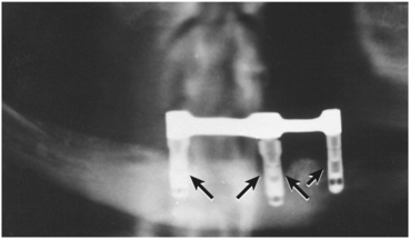
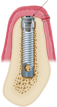
The second concern is that the maxillary sinus is in proximity to the edentulous ridge in the posterior maxilla. Frequently, as a result of resorption of bone and increased pneumatization of the sinus, only a few millimeters of bone are found between the ridge and the sinus (Fig. 14-16). In treat ment planning of implants in the posterior maxilla, the surgeon should plan to leave 1 mm of bone between the floor of the sinus and the implant. This allows the implant to be anchored apically into the cortical bone of the sinus floor. Adequate bone height for implant stability can usually be found in the area between the nasal cavity and maxillary sinus. If inadequate bone exists for implant placement and support, bony augmentation through the sinus may be performed as discussed in the section on advanced surgical techniques.
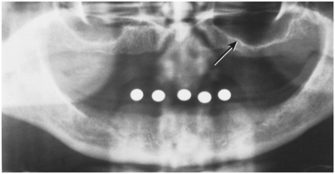
FIGURE 14-16 Radiograph illustrates how pneumatization of maxillary sinus and crestal bone loss together produce residual ridge that is not capable of supporting implant (arrow).
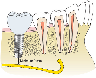
The posterior mandible poses some limitations on implant placement. The inferior alveolar nerve traverses the mandibular body in this region. Treatment planning of implant length must allow for a 2-mm margin from the apical end of the implant to the superior aspect of the inferior alveolar canal (Fig. 14-17), which is an inviolable guideline to avoid damaging the inferior alveolar nerve and causing numbness of the lower lip. If inadequate length is present for even the shortest available implant, then nerve repositioning, grafting, or a conventional non–implant-borne prosthesis can be considered. These procedures are discussed further in the section on advanced surgical techniques.
Implants placed in the posterior mandible are usually shorter, do not engage cortical bone inferiorly, and must support increased biomechanical occlusal force once loaded. As a result, slightly increased time for integration may be beneficial. Additionally, if short implants (8 to 10 mm) are used, it is advisable to “overengineer” and to place more implants than usual to withstand the occlusal load.
The width of the residual ridge must also be carefully evaluated in the posterior mandible. Attachment of the mylohyoid muscle may maintain bony width along the superior aspect of the ridge, although a deep lingual depression forms immediately below (Fig. 14-18). This area should be palpated at the time of evaluation and visualized at surgery.
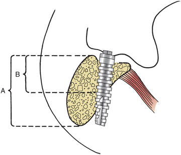
FIGURE 14-18 Mylohyoid muscle will maintain bone along its attachment on medial of mandibular body. Frequently, a significant depression is found just below this. If implant position and angulation do not compensate, lingual perforation may result. Apparent bone height on radiograph (A) and actual height in desired area (B) are demonstrated.
The anterior mandible is usually the most straightforward area for treatment planning with respect to anatomic limitations. The mandible is usually wide enough and tall enough to provide adequate bone for implant placement. The bone quality is usually excellent, which makes this the area of the jaw that requires the least time for integration to occur. In the premolar area, care must be taken to ensure that the implant is placed anterior to the mental foramen. The inferior alveolar nerve usually courses anterior to the mental foramen before turning posteriorly and superiorly to exit the mental foramen. Because the nerve may be as much as 3 mm anterior to the foramen, the most posterior extent of the implant should be a minimum of 5 mm anterior to the mental foramen (Fig. 14-19).
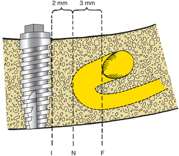
FIGURE 14-19 Most anterior extent of bony mental foramen (F) is frequently located posterior to most anterior extent of mental nerve before its exit from bone (N). Most posterior aspect of implant (I) should be placed a minimum of 2 mm from nerve. This means that implant must be placed 5 mm anterior to most anterior aspect of bony mental foramen.
Informed Consent
Once adequate information is obtained to allow formulation of a treatment plan, informed consent is obtained before surgery. This step is best accomplished using a team approach involving the surgeon and the restorative dentist. The combined surgical and restorative plan and feasible nonimplant alternatives are presented to the patient so that he or she can make an informed decision whether to proceed with treatment.
Models of various implant-supported prostheses can be used to demonstrate the proposed treatment. The patient should be informed about the timing of surgery, the possible necessity of two surgical procedures, and the expected time between the initial surgery and the delivery of the finished prosthesis. The patient should also be informed of the need to leave existing dentures out and the length of time this must be done. The patient should be informed about potential short- and long-term risks, such as nerve injury, infection, and implant failure. Finally, a clear understanding of the expected cost of the proposed treatment should be reached. After this information is discussed, the patient should sign a written informed consent document.
Surgical Guide Template
The coordination of the surgical and prosthetic procedures through proper treatment planning is one of the most critical factors in obtaining an ideal esthetic and functional result for the implant restoration. The surgical guide template is a critical factor for implants placed in an esthetic area because even slight variations of angulation can have large effects on the appearance of the final restoration. The construction of the surgical guide template is nearly indispensable for those patients for whom it is necessary to optimize implant placement to ensure correct emergence profiles in the anterior esthetic zone. The four objectives of using a surgical template for the partially edentulous patient are as follows: (1) delineate embrasure, (2) locate implant within tooth contour, (3) align implants with long axis of completed restoration, and (4) identify level of cementoenamel junction or tooth emergence from the soft tissue. The template most useful in the anterior esthetic zone is a clear resin template, which allows a surgeon ease of access to the bone and uninterrupted visual confirmation of frontal and sagittal angulations (Fig. 14-20). Although the underlying bone may dictate some minor variation, the surgeon must stay as close as possible to the template during implant placement (Fig. 14-21). The ultimate result should allow the surgeon to place the implant optimally in bone while maintaining the angulation that will provide the least compromise of the final restoration.
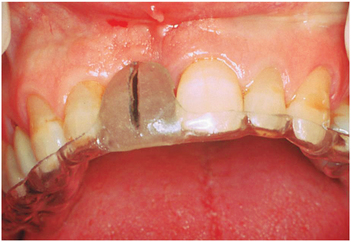
FIGURE 14-20 Anterior surgical guide. Thickness should equal that of porcelain on final restoration. Distance from facial of tooth to be restored and lingual extent of template should be approximately 2 mm. The embrasures, tooth form, position, angulation, and cementoenamel junction are clearly identifiable.
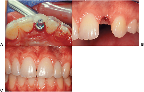
FIGURE 14-21 A, Surgical guide in place with paralleling pin identifying the position of the implant, which is well within the contours of the planned restoration. B, Resulting implant position, angulation, and depth produces natural contours that (C) result in ideal form of the final restoration.
In posterior edentulous areas, a similar template is fabricated with directional holes drilled through the template. This surgical template provides the surgeon with a guide to locate the implant placement accurately and direct the long-access inclination of the implant (Fig. 14-22).
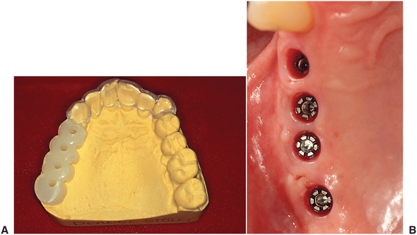
FIGURE 14-22 A, Posterior surgical template used to align drill path of insertion. Individual embrasure spaces are delineated by template. B, Resulting position of implants.
The surgical template for the completely edentulous mandible should allow the surgeon maximal flexibility to select the implant position in the resorbed bone but yet provide guidance as to the angulation requirements of the restorative dentist. A template with a labial flange that simulates the labial surface of the anticipated position of the denture teeth but that is cut out on the lingual aspect satisfies these two requirements (Fig. 14-23). The surgeon places the implants within the arch form, as close to the surgical template as possible, to prevent the placement of the implants too far lingually or labially.

FIGURE 14-23 A and B, Edentulous surgical templates should delineate arch form and facial tooth location. Access for the surgeon and maximal flexibility to select the implant position in the resorbed bone while guiding angulation is achieved. A template with a labial flange that simulates the labial surface of the anticipated position of the denture teeth but that is cut out on the lingual aspect satisfies these two requirements.
BASIC SURGICAL TECHNIQUE
Successful implant placement relies on adequate bone quantity and quality. The availability of bone at the implant site is based on many variables. Some of the variables controlled by the dentist include use of atraumatic extraction techniques, preservation of the bony socket, selection of an interim prosthesis, and timing of implant placement.
Atraumatic Extraction
An intact socket is critical to achieve full bony regeneration. A “four-walled” defect produced by an intact socket will regenerate bone with minimal loss of width and contour. Lone standing teeth and teeth with prominent labial roots pose a risk to the labial plate. Atraumatic extraction with a periotome preserves the contour and integrity of this bone.
Socket Preservation
After extraction, some marginal resorption of bone takes place and the residual ridge may thin. This bone loss can compromise ideal implant placement. To encourage consistent healing and lessen the time between extraction and implant placement, reconstruction of the socket may be considered. A number of alloplastic and allogeneic grafts or xenografts are available. Alternatively, the implant itself may be placed into the residual socket. If there is adequate stability, this may aid in preservation of the bony contour. Indications for this are discussed later in this chapter. Even if the extraction site meets the requirements for immediate implant placement, it may be desirable to delay implant placement. If the socket is reconstructed with a graft, as little as 2 months is an adequate waiting period before implant placement. During this time the overlying soft tissue heals, and primary closure is easier at the time of implant placement.
This time is generally long enough to allow remodeling of the socket and, in the case of multirooted teeth, some filling of the socket with bone. In this situation, implants are placed using the same technique described for routine implant placement. The bone in the area of surgery is softer but generally allows preparation of the implant recipient site with little modification. No increase in integration time is generally necessary in this situation.
Interim Prosthesis Design
The interim prosthesis should be designed to aid in contouring the residual soft tissue. It is important that the tissue-borne provisional prosthesis not produce excess pressure on the underlying soft tissue and bone, particularly on the interdental papilla. An ovate style pontic with open embrasures to allow room for the normal papilla anatomy is preferable to a ridge lap design (Fig. 14-24).
Timing of Implant Placement
Excessive delay between extraction and implant placement may result in bone loss. Although a period of 2 to 6 months following extraction can aid in improved bone quality, longer delay may result in bone resorption. Implant placement produces functional stresses in the bone that helps maintain contour and bulk. In the absence of a natural tooth or an implant, bone will resorb. Excessive resorption may necessitate grafting procedures before an implant can be placed. Patients undergoing extraction should be educated about this window of opportunity.
Implant Placement
Implant surgery can be performed in an ambulatory setting with local anesthesia. Such surgery requires more time than other surgical procedures, so the use of conscious sedation is often beneficial. Although implant placement is less traumatic than tooth extraction, the patient has the expectation that it will be more so. Preoperative patient education and conscious sedation help to lessen anxiety.
Preoperative antibiotic prophylaxis is usually recommended. An oral dose of 2 g penicillin V 1 hour preoperatively or an intravenous dose of 1 million units penicillin G immediately preoperatively are effective. Alternative medications include 600 mg clindamycin orally or intravenously. No postoperative antibiotic administration is necessary.
Profound local anesthesia is required for precise implant placement. In the atrophic anterior mandible, block anesthesia, as well as infiltration anesthesia, is sometimes required to achieve this goal.
Adequate aseptic technique minimizes the risk for postoperative infection. The patient can rinse with 15 mL 0.12% chlorhexidine gluconate (Peridex) for 30 seconds immediately before the start of surgery. This significantly reduces the oral microbial count and maintains a reduced level for 1 hour or more. The surgeon and assistants should follow sound aseptic techniques using masks, sterile gloves, and sterile instrumentation. A complete sterile surgical gown is not required.
Proper implant placement is a technically demanding procedure requiring precision. Therefore, adequate visualization is critical. Carefully directed lighting and adequate retraction are necessary.
Soft Tissue Incision
Several types of incisions can be used to gain access to the residual ridge for implant placement. The incision should be designed to allow convenient retraction of the soft tissue for unimpeded implant placement. The incision should preserve or increase the quantity of attached tissue and preserve local soft tissue esthetics. Access can be gained through open or closed techniques. The closed technique uses a tissue punch to gain access only to the crestal bone. The closed technique relies on the surgeon’s ability to determine bone morphology without direct visualization and works best with wide, uniform ridges.
An open approach is more predictable but also more invasive. When the quantity of attached tissue is adequate and the underlying bone is expected to be of adequate width, a simple crestal incision is the incision of choice (Fig. 14-25). Closure of the incision must be done carefully, because the implants lie directly beneath the incision. This approach works well in the mandible and posterior maxilla. An incision placed slightly palatal may be a better choice in the anterior maxilla, especially when esthetics is of concern, because it preserves facial contour and soft tissue bulk. In the esthetic zone, an incision that preserves the adjacent papilla may be helpful.
Preparation of the Implant Site
After the bone is exposed, the surgical guide template is positioned and a preliminary assessment of the implant site is made. The residual ridge may have areas of unevenness or sharp ridges that are best reduced with a rongeur or a bur before drilling for implant placement. Fibrous tissue should also be removed so that it will not be incorporated into the implant site.
Placement procedures for all implant systems require atraumatic preparation of the recipient site. A low-speed (1500 to 2000 rpm), high-torque handpiece and copious irrigation are necessary to prevent excess thermal injury to the bone. Irrigation may be externally applied or internally directed through the drills. Recommendations of the specific implant manufacturer should be followed because they relate to the type of irrigation and the allowable speed of the drilling equipment.
The implant site is located using the surgical guide template, which may also assist in directing the angulation of the implant. All implant systems have an initial small-diameter drill that is used to mark the implant site. With the initial drill the center of the implant recipient site is marked and the initial pilot hole is prepared (Fig. 14-26). The implant recipient site preparation continues by drilling with a series of gradually larger burs.
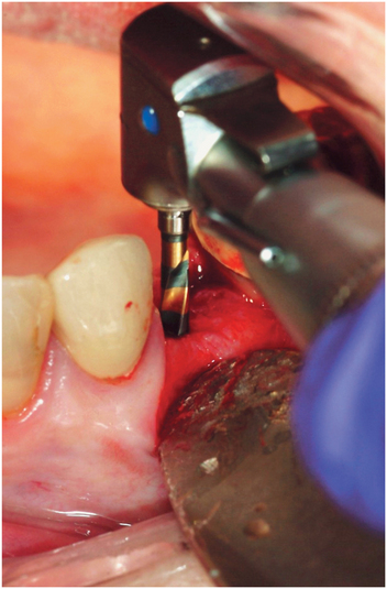
FIGURE 14-26 Initial position, angulation, and depth is established with the first twist drill in the sequence.
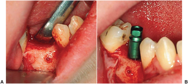
A paralleling pin is placed in the initial preparation to check alignment and angulation (Fig. 14-27).
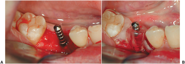
FIGURE 14-27 A, Initial osteotomy has been prepared, and paralleling pin is placed to evaluate position and angulation. B, The surgical guide can be placed over the paralleling pin for confirmation.
Once the initial preparation for the implant is determined to be appropriate, it is sequentially enlarged to a dimension that precisely conforms to the dimensions of the implant. Care must be taken to maintain the angulation and depth established by the initial drill. Tapered implants may require separate drills for each depth. Failure to follow implant manufacuturer protocols correctly regarding drilling sequence may result in implants that are placed too deep or too shallow or that have inadequate stability or excessive insertion forces leading to bone necrosis.
Implant Placement
After the desired depth and diameter of the recipient site is accomplished, the implant is placed. For titanium implants, an uncontaminated surface oxide layer is necessary to obtain osseointegration. Contamination by touching the implant with instruments made of a dissimilar metal or by contact with cloth, soft tissue, or even surgical gloves may affect the degree of osseointegration. Hydroxyapatite-coated implants are also sensitive to contamination. Hydroxyapatite is porous and easily absorbs liquids or oils and becomes contaminated with fibers from cloth drapes or powder from surgical gloves.
Although some implants are pressed into place, most are threaded and must be screwed into place. Implants can be screwed in place by a handpiece at very low speeds (e.g., 15 rpm) or by hand (Fig. 14-28). Final tightening in most cases is done by hand with a ratchet. Modern threaded implants are self-tapping. However, in very dense bone, the recipient site may need to be tapped to produce threads within the bone, thereby avoiding excess torque and heat during implant placement. Excess torque can damage the antirotational features of the implant, may crush the bone leading to necrosis, or may even induce fractures.
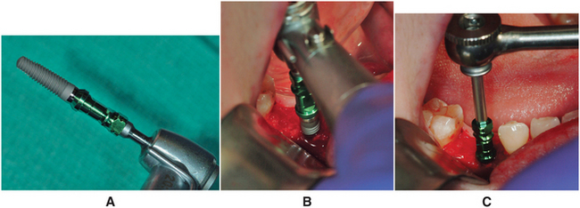
FIGURE 14-28 A, Most implants are threaded and must be screwed into place. B, This can be done by handpiece at very low speeds (e.g., 15 rpm) or by hand. C, Final tightening is done with a ratchet.
After all implants are placed, the wound is closed. A tension-free closure is important to prevent wound dehiscence.
In some cases the surgeon may plan to leave the implant exposed following placement. In these cases a longer healing post is added to the implant and the soft tissue is contoured around the post that extends from the top of the implant through the soft tissue into the oral cavity. This technique eliminates the need for a second-stage uncovering of the implant and may produce a more mature gingival contour. This technique increases requirements for oral hygiene care of the exposed implant because of the increased risk of trauma and mobility and should be reserved for implants with good primary stability at the time of placement.
Postoperative Care
A radiograph should be taken postoperatively to evaluate the position of the implant in relation to adjacent structures, such as the sinus and inferior alveolar canal, and relative to other implants.
Patients should be provided analgesics. Mild- to moderate-strength analgesics are usually sufficient. Rarely are potent oral analgesics required. Patients can also be instructed to use 0.12% chlorhexidine gluconate (Peridex) rinses for 2 weeks after surgery to help keep bacterial populations at a minimum during healing. The patient is evaluated weekly until soft tissue wound healing is complete (approximately 2 to 3 weeks). If the patient wears a tissue-borne denture over the area of implant placement, the denture can be relined with a soft liner after 1 week and may be worn. Interim partial dentures or orthodontic retainers with an attached pontic may be worn immediately but must be contoured to avoid soft tissue loading over the implant site.
Uncovering
The length of time necessary to achieve integration varies from site to site and may require modification based on the particular situation. Successful loading with shorter integration times has been reported when various protocols are followed, and immediate loading in controlled settings has reported success (Table 14-2 gives conventionally accepted times for integration based on historical experience, which should serve as a reference point). Although shorter times may be possible, longer times may be required if the bone quality at surgery was poor or if there was a question regarding the adequacy of bone-to-implant interface at the time of placement.
In a single-stage system the implant remains exposed after surgery and throughout the healing phase. After appropriate integration time, restoration can proceed. In a two-stage system the implant must be uncovered before restoration. The goals of surgical uncovering are to attach the abutment accurately to the implant, preserve attached tissue, and recontour and thin tissue or add form and thickness to existing tissue. This may be accomplished by one of the following general techniques: the tissue punch, crestal incision, flap repositioning, or soft tissue grafting. Each has its own advantages and indications (Box 14-4).
The simplest method of implant uncovering is the tissue punch (Fig. 14-29). This method of uncovering is easy to perform, only minimally disturbs the tissue surrounding the implant, and produces minimal patient discomfort. To use this technique, the implant must be located with certainty below the tissue. Use of the punch is contraindicated if inadequate attached tissue will remain after the punch is used. The punch also has the slight disadvantage of not allowing visualization of the bone. If a graft was placed or if there was some question regarding the relationship between the marginal bone and the implant, this technique would not allow assessment at the time of uncovering, and nonresorbable guided tissue regeneration membranes could not be removed. This technique also makes visualization of the abutment–to–implant body interface difficult. The operator must rely on tactile sense to determine whether the abutment is completely seated on the implant body.
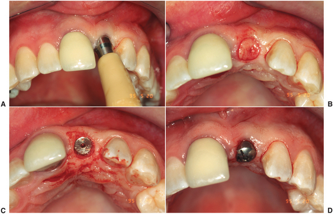
FIGURE 14-29 A to D, The simplest method of implant uncovering is the tissue punch. This method of uncovering is easy to perform, only minimally disturbs the tissue surrounding the implant, and produces minimal patient discomfort. To use this technique, the implant must be located with certainty below the tissue.
If the implants cannot be palpated or the clinician needs to visualize the marginal bone, a crestal incision over the implant is indicated. If sufficient attached tissue is found, a punch or scissors can be used to contour the edge of the flap to conform to the implant before wound closure. This technique also heals rapidly because primary closure exists. This technique also requires adequate attached tissue.
If attached tissue surrounding the implant is limited or inadequate, an apically repositioned flap is the uncovering method of choice. A crestal incision developed in a supraperiosteal plane is performed to develop a split-thickness flap. The flap is then sutured over the facial surface at a more apical level. Healing occurs by secondary intention. This technique requires the longest healing time and is more painful. The technique preserves and increases the amount of attached soft tissue but does not improve tissue thickness.
In some situations the bulk of soft tissue is not adequate to produce proper contour around the implant. This is especially a problem in the anterior maxilla where, despite adequate osseous contour and proper implant placement, a localized depression at the facial margin of the crown is found that will compromise esthetics. In this situation a pedicled or free connective tissue graft is an effective way to restore soft tissue form around the implant (Fig. 14-30). These procedures allow minor changes in the tissue height around the implant crown but cannot substitute for adequate osseous form that must always be maintained (or reestablished first).
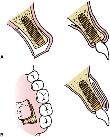
FIGURE 14-30 A, Pedicled connective tissue graft from the palate can be used to augment the labial soft tissue contour. B, Free connective tissue graft can also be used to provide the same outcome.
In situations in which the overlying tissue is thick, it may be necessary to recontour tissue. A carbon dioxide laser or electrocautery is effective. Laser or bipolar cautery poses less risk of damage to the implant or bone than conventional monopolar cautery.
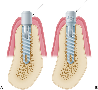
After the implant is exposed, the implant abutment is placed. Two approaches can be used to do this: One approach is to place the abutment that the restorative dentist will use in the restoration. This is effective in the mandible and posterior maxilla where esthetics is of less concern. The other technique is to place a temporary healing abutment that will remain until the tissue heals and will then be discarded and replaced by the final prosthesis. This may be a factory or custom-made abutment. A custom abutment helps contour soft tissue for better esthetic results. Custom abutments are made from an index of implant position recorded at the time of placement.
When the abutment is placed, it is important that it be completely seated on the implant body without gaps or intervening soft or hard tissue. In systems that have antirotational facets built into the implant, these must be aligned to allow complete seating of the abutment. The abutment-to-implant interface should be evaluated radiographically immediately after uncovering. If a gap is present, the abutment must be repositioned.
COMPLICATIONS
Potential complications of implant placement include improper angulation or positioning of the implants; perforation of the inferior border, the maxillary sinus, or the inferior alveolar canal; dehiscence of the buccocortical or linguocortical plate; mandibular fracture; and soft tissue wound dehiscence.
Variation in the position or angulation of the implant results when the anatomy found at surgery requires implant placement different from that planned preoperatively. This should be avoided by grafting bone and/or soft tissue to allow implant placement in the desired location and angle. In the event that ideal angulation has not been achieved, a variety of prosthodontic attachments are available to salvage implants that have nonideal angulation.
Sinus perforation occurring during drilling for implant placement is unlikely to cause serious sequelae. Shorter implant length than planned may be necessary to prevent the implant from extending too far into the sinus. Usually the resistance provided by the cortical bone of the maxillary sinus floor is encountered before a perforation results and can serve as an indicator that maximum depth has been reached. If perforation does occur and the implant is placed only a short distance into the maxillary sinus, a problem is not likely. Similar guidelines exist for perforation of the inferior border of the mandible. The apical portion of the implant should be within the cortical bone of the inferior border.
Perforation of the inferior alveolar canal is a serious problem. Local infiltration over the bone crest rather than inferior alveolar nerve block may facilitate identification of this at surgery because the patient will be adequately anesthetized for implant placement but feel a sharp pain if the canal is perforated. Perforation of the canal may also be accompanied by sudden increased bleeding. If this occurs, an implant shorter than planned should be used. If the implant appears to extend into the inferior alveolar canal on the postoperative radiographs, the implant should be removed immediately and a shorter implant should be placed. If no indication of perforation exists and no radiographic evidence of violation of the canal is noted, patients may still have postoperative neurosensory alteration. This may be from traction on the mental nerve, from direct injury during implant placement, or from extraosseous hematoma or soft tissue swelling. These patients should be followed closely. Deficits of this nature generally resolve with time but may require surgical intervention if they persist and are bothersome to the patient.
Perforation of the buccocortical or linguocortical plates may occur when resorption has resulted in a thin ridge along the planned implant site. A simple solution is to countersink the implant until the depth of the implant recipient site is adequate for the length of the implant. This may leave excess bone height on the lingual, mesial, and distal surfaces. At the time of uncovering there may be bone growth over the implant that requires removal. If the sharp crest is generalized and several implants are to be placed, the entire crest can be reduced down to a suitable width. If a dehiscence does occur, it should be evaluated and a decision should be made regarding treatment. A small, 1- to 2-mm bony dehiscence on the buccal aspect of an implant generally requires no additional treatment. Larger defects, particularly if the implant is short, may compromise stability. If this results, the defect can be grafted with bone or a bone substitute (Fig. 14-31). This technique is more fully discussed in the section on advanced surgical techniques.
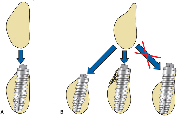
FIGURE 14-31 In an ideal situation (A), adequate bone on buccolingual areas for implant placement exists. This may not occur when there has been resorption of buccal bone (B). Acceptable ways to handle this include removal of sharp crest to level of adequate width for implant or placement of bone graft over buccal dehiscence that results.
An unusual complication of implant placement in the mandible is mandibular fracture. Fracture is most likely when the mandible is extremely atrophic, when preexisting metabolic disease (e.g., osteoporosis) is seen, or when the patient has a history of postoperative trauma. Failure to tap threaded implants in very dense mandibular bone may also be associated with fracture. Management may require routine fracture management with rigid internal fixation and bone grafting to increase the bone mass of the mandible.
Soft tissue wound dehiscence may occur, allowing part of the implant to become exposed. If this occurs, no attempt should be made to resuture the wound because the only result will be increased wound dehiscence. Chlorhexidine rinses can be used until soft tissue healing has occurred. If the tissue is healthy but the implant remains exposed, a soft toothbrush dipped in chlorhexidine should be used to keep the implant clean throughout the integration period. This generally does not result in increased implant failure because single-stage implants are purposely left exposed throughout osseointegration and have comparable success as two-stage systems.
CLINICAL IMPLANT COMPONENTS
Osseointegrated implants are generally designed to support screw- and cement-retained implant restorations. Contemporary implant systems offer many advantages over conventional dental restorations and original systems (Box 14-5). Implant restorations require the use of several component parts that heretofore had not been routinely described in conventional dental education. For the inexperienced implant clinician, the sheer number of parts within one system often creates an overwhelming obstacle to getting involved in implant dentistry. This section describes in generic terms the component parts typically necessary to restore a screw-retained, osseointegrated implant. It should be noted that the components might differ slightly in design and materials among implant systems.
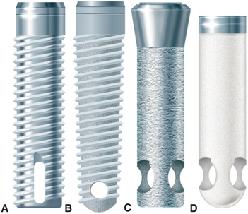
Implant Body
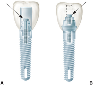
The dental implant body, often referred to as the fixture, is the component placed within the bone during first-stage surgery. The implant body may be a threaded or nonthreaded root form and is ordinarily made of titanium or titanium alloy of varying surface roughness, with or without a hydroxyapatite coating (Fig. 14-32). Although some controversy exists regarding the optimum shape and surface coating for an implant in different parts of the mouth, the significant factors for success are precise placement, atraumatic surgery, unloaded healing, and passive restoration. All contemporary dental implants have an internally threaded portion that can accept second-stage screw placements. These implants also may incorporate an antirotational feature within the design of the fixture body. If it is incorporated, the antirotational feature may be internal or external. Implant bodies can also be classified as one-stage or two-stage. One-stage implants project through the soft tissue immediately after stage I surgery. Two-stage implants are typically covered with soft tissue at the time of surgery. When a tall healing screw or cap is placed on a two-stage implant to project it through the tissue at the time of placement, this is referred to as “using a two-stage implant with a one-stage protocol.”
Healing Screw
During the healing phase after first-stage surgery, a screw is normally placed in the superior aspect of the fixture. The screw is usually low in profile to facilitate the suturing of soft tissue in the two-stage implant or to minimize loading in the one-stage implant (Fig. 14-33). At second-stage surgery, the screw is removed and replaced by subsequent components. In some systems the screw is made slightly larger than the diameter of the implant, which facilitates abutment placement by ensuring that bone does not grow over the edge of the implant. The implant surgeon should always be sure that the healing screw is completely seated after stage I surgery to prevent bone from growing between the screw and the implant. If this occurs, removing the bone may damage the superior surface of the implant and affect the fit of subsequent components.
Interim Abutment
Interim abutments are dome-shaped screws placed after second-stage surgery and before insertion of the prosthesis. The abutments range in length from 2 to 10 mm and project through the soft tissue into the oral cavity. The abutments may screw directly into the fixture or, in some systems, onto the abutment immediately after second-stage surgery. Those abutments that screw onto the abutment are commonly referred to as healing caps (Fig. 14-34). Both components are made of titanium or titanium alloy. In areas where esthetics is paramount, healing after second-stage surgery should be sufficiently complete around an interim abutment to stabilize the gingival margin before final prosthesis construction. At this time, abutments of appropriate length are selected to ensure that the metal-porcelain interface of the restoration will be located subgingivally. In areas where tissue esthetics is not crucial, adequate healing for impressions usually takes 2 weeks after second-stage uncovering. In esthetic zones, 3 to 5 weeks may be required before abutment selection.
Abutment
Abutments are the component of the implant system that screw directly into the implant. Abutments eventually support the prosthesis in screw-retained restorations, inasmuch as they accept the retaining screw of the prosthesis. For cement-retained restorations, abutments may be shaped like a conventional crown preparation. Abutments take many forms (Fig. 14-35). The walls of abutments are usually smooth, polished, and straight-sided titanium or titanium alloy. The lengths range from 1 to 10 mm. In nonesthetic areas, 1 to 2 mm of titanium should be allowed to penetrate the soft tissue to maximize the patient’s ability to clean the prosthesis (Fig. 14-36). In esthetic areas an abutment can be selected to allow porcelain to be carried subgingivally for optimum esthetics (Fig. 14-37). In implant systems that incorporate an antirotational feature, the abutment must have two components that move independently of each other: One engages the antirotational feature, and the other secures the abutment within the fixture (Fig. 14-38). With angled abutments a similar technique is used to correct divergently placed implants (Fig. 14-39). Some systems have included tapered or wide-base abutments, which allow teeth with larger cross-sectional diameters to be restored with more physiologic contours. The nonsegmented implant crown (UCLA) bypasses the abutment portion by means of a sleeve waxed directly to the implant. Use of nonsegmented implant crowns may be necessary when soft tissue thickness is less than 2 mm. Abutments made entirely of ceramic onto which all-ceramic crowns can be cemented are gaining popularity for the anterior part of the mouth. The ceramic components are usually made of sintered alumina, zirconia, or a combination of the two (Fig. 14-40).
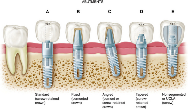
FIGURE 14-35 Types of abutments (left to right). A, Standard. Length can be selected to make the margin subgingival or supragingival. B, Fixed. This abutment is much like a conventional post and core. It is screwed into the implants, has a prepared finish line, and receives a cemented restoration. C, Angled. This type is available when implant angles must be corrected for esthetic or biomechanical reasons. D, Tapered. This type can be used to make the transition to restoration more gradual in larger teeth. E, Nonsegmented, or direct. This type is used in areas of limited interarch distance or areas where an esthetic outcome is important. The restoration can be built directly on the implant, so there is no intervening abutment. This direct restoration technique as been called the UCLA abutment. (Rosenstiel SF, Land MF, Fujimoto J: Contemporary fixed prosthodontics, ed 4, St Louis, 2006, Mosby.)
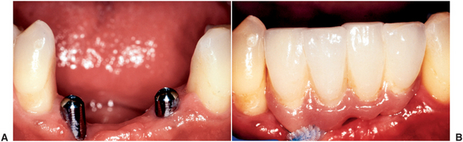
FIGURE 14-36 A, Interim abutments projecting through the soft tissue. B, Implant restorations supported by standard abutments that allow easy access for oral hygiene. (Rosenstiel SF, Land MF, Fujimoto J: Contemporary fixed prosthodontics, ed 4, St Louis, 2006, Mosby.)
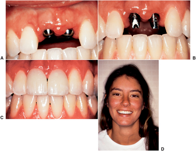
FIGURE 14-37 A, Interim abutments projecting through the tissue for implant restoration of maxillary central incisors. B, Fixed abutments selected with margins 1 to 2 mm subgingival. C, Completed, cemented restorations. D, Overall esthetic result. (Rosenstiel SF, Land MF, Fujimoto J: Contemporary fixed prosthodontics, ed 4, St Louis, 2006, Mosby.)
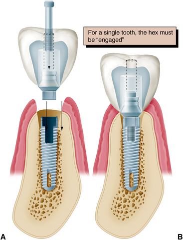
FIGURE 14-38 A and B, When an antirotational feature is to be engaged by the abutment, one component of the abutment (the sleeve) must fit the hexagon, whereas the other (the screw) independently tightens the components together. (Rosenstiel SF, Land MF, Fujimoto J: Contemporary fixed prosthodontics, ed 4, St Louis, 2006, Mosby.)
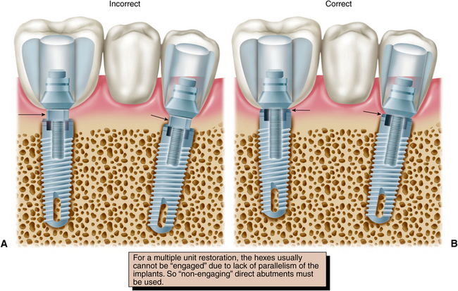
FIGURE 14-39 For a multiple unit restoration, the hexes (arrows) usually cannot be “engaged” (A) because of lack of parallelism of the implants. So nonengaging direct abutments (arrows) must be used (B). (Rosenstiel SF, Land MF, Fujimoto J: Contemporary fixed prosthodontics, ed 4, St Louis, 2006, Mosby.)
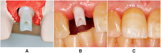
FIGURE 14-40 A, Zirconia abutment seated on the cast and ready for fabrication of all-ceramic restoration. B, Zirconia abutment seated in the mouth. C, All-ceramic restoration.
The choice of abutment size depends on the vertical distance between the fixture base and opposing dentition, the existing sulcular depth, and the esthetic requirements in the area being restored. For acceptable appearance, an anterior maxillary crown may require 2 to 3 mm of subgingival porcelain at the facial gingival margin to create the proper emergence profile and appearance, whereas fixtures in the posterior maxilla or mandible may have margin termination at or below the gingival crest.
Impression Coping
Impression copings facilitate transfer of the intraoral location of the implant or abutment to a similar position on the laboratory cast. Impression copings may screw into the implant or onto the abutment and are customarily subdivided into fixture types or abutment types (Fig. 14-41).
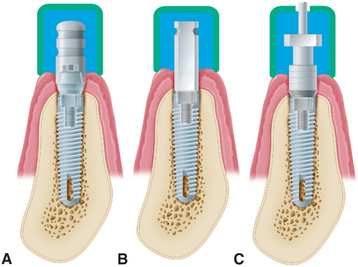
FIGURE 14-41 Types of impression copings. A, A one-piece coping (screws onto abutment) is used if the abutment does not need to be changed on the laboratory cast. B, A two-piece coping (transfer/closed tray) is attached directly to the fixture if the abutment does need to be changed on the cast (it should have a flat side if angle correction is necessary). C, A two-piece coping (pickup/open tray), used to orient the antirotational feature or to make impressions of very divergent implants. (Rosenstiel SF, Land MF, Fujimoto J: Contemporary fixed prosthodontics, ed 4, St Louis, 2006, Mosby.)
Both types can be further subdivided into transfer (indirect) and pickup (direct) types. With the transfer impression coping in place, an impression is made intraorally, after radiographs are taken to confirm that the implant components are properly assembled. This requirement is especially important when an antirotational feature is involved. Heavier body impression materials (e.g., polyvinyl siloxane and polyether) are usually recommended, although any conventional impression material can be used. When the impression is removed from the mouth, the impression coping remains in place on the implant abutment or on the fixture. The coping is then removed from the mouth and joined to the implant analog before being transferred to the impression in the proper orientation. Before an implant impression is taken, a radiograph should be made to ensure that the components are properly assembled. This is especially important when an antirotational feature is involved.
Implant Analog
Implant analogs are made to represent exactly the top of the implant fixture or the abutment in the laboratory cast. Therefore, analogs can be classified as fixture analogs and abutment analogs (Fig. 14-42). Both types of analog screw directly into the impression coping after it has been removed from the mouth, and the joined components are returned to the impression before pouring. The final impression should be poured in dental stone or die stone. The gingival tissues can be reproduced by injecting an elastomer (e.g., Permadyne, 3M, St. Paul, Minnesota) to represent soft tissue around the implant analog before pouring. This facilitates removal of the impression coping from the stone cast and the placement of subsequent abutments without breaking the stone and losing the reference point of the soft tissue (Fig. 14-43).
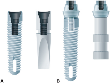
FIGURE 14-42 Implant analogs. These represent implants or abutments. A, Analog that duplicates the top of the implant. B, Analog that duplicates the top of the abutment. (Rosenstiel SF, Land MF, Fujimoto J: Contemporary fixed prosthodontics, ed 4, St Louis, 2006, Mosby.)
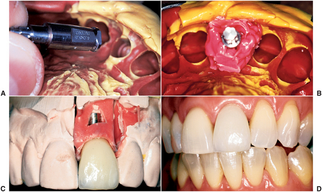
FIGURE 14-43 A and B, Polyether impression material injected around an implant analog before the impression is poured. The gingival material should not cover any retention features of the analog. C, The impression material reproduces the patient’s soft tissue contours adjacent to the implant. The impression coping may be removed and other components inserted without losing the associated anatomic landmarks. D, Completed restorations. (Rosenstiel SF, Land MF, Fujimoto J: Contemporary fixed prosthodontics, ed 4, St Louis, 2006, Mosby; courtesy Dr. C. Pechous.)
Abutment analogs are generally attached to an implant impression coping. Implant body impression copings are normally attached to implant body analogs. The advantage of using the implant body analog is that the abutments can be changed in the laboratory. Also, if a flat-sided impression coping has been used to orient the threads or the hexagon of the implant body analog properly, the decision to correct for less than optimal implant angulation can be deferred until the laboratory stage. If the clinician is confident that the appropriate abutment has been selected, using the abutment impression coping and abutment analog can simplify the procedure. If a supragingival abutment margin has been selected, a soft tissue cast is not necessary.
Waxing Sleeve
Waxing sleeves are attached to the abutment by the relating screw on the laboratory model. The sleeves eventually become part of the prosthesis. In nonsegmented implant crowns, the sleeves are attached directly to the implant body analog in the cast. Commonly referred to as UCLA abutments, the sleeves may be plastic patterns that are burned out and cast as part of the restoration framework, precious metal that is incorporated in the framework when it is cast to the precious alloy cylinder, or a combination of each. Use of a metal waxing sleeve ensures that two machined surfaces are always in contact. The cast surface of the plastic waxing sleeve may be retooled before it is returned to the fixture. Waxing sleeves are available in several vertical dimensions. Tall ones can be shortened to conform to the requirements of the occlusal plane. Today, most waxing sleeves are a combination of gold alloy and plastic (Fig. 14-44). This combination allows the advantage of plastic at the waxing surface and precise metal-to-metal tolerances at the implant level.
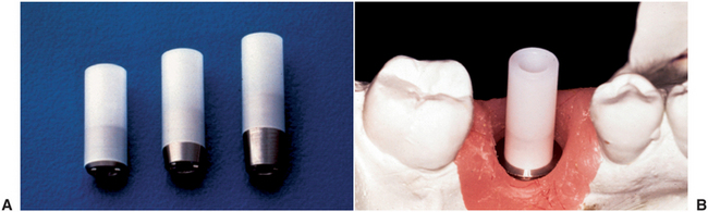
FIGURE 14-44 A, Waxing sleeves with gold alloy base and plastic extension. B, On the laboratory cast the technician can wax to the plastic extension. The wax and plastic are burned out, and the new alloy is “cast to” the original alloy base. (Rosenstiel SF, Land MF, Fujimoto J: Contemporary fixed prosthodontics, ed 4, St Louis, 2006, Mosby.)
Prosthesis-Retaining Screw
Prosthesis-retaining screws penetrate the fixed restoration and secure it to the abutment (Fig. 14-45). The screws are tightened with a screwdriver and attach nonsegmented crowns to the body of the implant. The screws generally are made of titanium, titanium alloy, or gold alloy and may be long (which allows them to penetrate the total length of the implant crown) or short (which requires countersinking them into the occlusal surface of the restoration). Screws that are countersunk must be covered by an initial layer of resilient material (e.g., gutta-percha, cotton, or silicone). A subsequent seal of composite resin is placed over the resilient plug.
IMPLANT PROSTHETIC OPTIONS
Completely Edentulous Patients
At least three prosthetic implant options exist for the completely edentulous patient. The options include (1) the implant- and tissue-supported overdenture, (2) the all implant-supported overdenture, and (3) the complete implant-supported fixed prosthesis.
Implant- and Tissue-Supported Overdenture
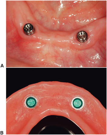
Completely edentulous patients have the most difficulty with the mandibular denture. Long-time denture wearers with a progressively worsening lower denture fit may derive great benefit from an implant- and tissue-supported overdenture. For this type of prosthesis, most commonly two implants are placed in the mandibular symphysis area between the mental foramina. These implants are used to retain and support the lower denture (Fig. 14-46).
Implant- and tissue-supported overdentures require a precise prosthetic technique. It is important that the retentive devices engage at the same time the posterior extensions contact the tissue and at the same time the teeth meet in occlusion. Although this option is not the answer for all patients, it provides an economical alternative for the patient who only needs additional retention and stability for a lower denture.
All Implant–Supported Overdenture
For those patients requiring more retention and stability for an upper and lower denture, the all implant-supported overdenture may be the answer. For implants to support the entire load, it is recommended that a minimum of four implants be placed in the lower jaw and six implants in the upper jaw. These implants are connected by a more extensive bar design using multiple clips for retention (Fig. 14-47).
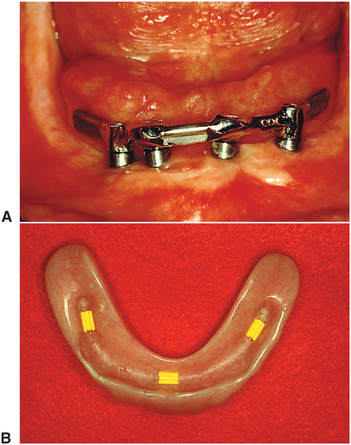
FIGURE 14-47 A, More extensive bar design with distal cantilevers joining four mandibular implants. B, Three Hader clips in an all implant-supported overdenture.
This type of prosthesis can provide the advantages of minimal tissue pressure, optimal access for hygiene, and optimal esthetics because the denture covers all metalwork. In the maxilla, this prosthesis can also have the additional advantages that the palate can be removed from the denture and that all air holes can be covered, which provides the patient with a better phonetic result. The disadvantage to this prosthesis is that it is still a removable prosthesis and must be removed for cleaning and maintenance, which does not satisfy that patient who seeks implant treatment for the psychological benefits of having a permanently retained restoration. A further disadvantage is that clip mechanisms wear over time and must be replaced.
Fixed Porcelain-Metal and Resin-Metal Restorations
For those completely edentulous patients who require nonremovable restorations the two options are (1) a fixed porcelain-fused-to-metal prosthesis (Figs. 14-5 and 14-48) or (2) a resin-metal fixed prosthesis (Fig. 14-49). The resin-metal prosthesis is a cast framework with resin denture material and teeth processed to the framework. Both of these options require a minimum of five implants in the mandible and six implants in the maxilla. One major determining factor for selecting the appropriate option is the amount of bone loss. Complete-mouth fixed rehabilitation can only be made esthetically pleasing if minimal bone loss has occurred. This type of restoration is best suited for those patients who have recently lost their natural dentition.
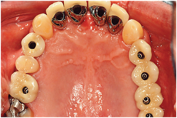
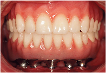
FIGURE 14-49 Facial view of mandibular metal-resin (hybrid) prosthesis. This prosthesis consists of precious metal substructure with acrylic resin and denture teeth processed to it.
For patients who have moderate bone loss, the prosthesis must replace bone and soft tissue, as well as teeth. In this case, the resin-metal prosthesis can best mimic soft tissue replacement. The advantage to the completely fixed restoration (the resin or porcelain prosthesis) is that it is completely retained by the patient at all times. Patients derive the maximal psychological benefit by having a restoration that is most like their natural teeth. Movement within the system is minimized, so the component parts tend to wear out less quickly.
Potential disadvantages for the complete-mouth fixed rehabilitation is that implants must be precisely placed, especially in the maxillary anterior esthetic zone, to achieve the ideal esthetic result. The relative benefit to each restorative option can be described to the edentulous patient (Box 14-6).
Partially Edentulous Patients
Major advantages from implant support can be derived in the partially edentulous patient. The two main indications for implant restorations in this patient are (1) the free-end distal extension when no terminal abutment is available and (2) a long edentulous span. In both of these situations the conventional dental treatment plan would include a removable partial denture. In the short edentulous span (including single-tooth restorations), the implant option is becoming a more popular choice. This selection is often made because natural abutments do not have to be prepared and improved access for hygiene can be realized. If the implants are 10 mm long or less, definite consideration should be given to adding a third implant to support a three-unit fixed partial denture.
Free-End Distal Extension
The implant dentist has two options in treating the patient missing terminal posterior abutments: (1) a single implant placed distal to the most posterior natural abutment and (2) a fixed prosthesis made to connect the implant and a natural tooth abutment. This situation is associated with a higher incidence of implant failure because of forces placed on the implant (Fig. 14-49). Alternatively, two or more implants can be placed posterior to the most distal natural tooth, and an implant restoration can be fabricated (Fig. 14-50).
Single-Tooth Implant Restorations
The use of single implants in restoring missing teeth is an attractive option for the patient and the dentist. This procedure requires careful implant placement and precise control of all prosthetic components. Single-tooth restorations supported by implants may be indicated in four situations: (1) patients with otherwise intact dentition, (2) dentition with spaces that would be more complicated to treat with conventional fixed prosthodontics, (3) distally missing teeth when cantilevers or removable partial dentures are not indicated, and (4) patient desire for treatment that will most closely mimic the missing natural tooth.
The five requirements for single-tooth crown are as follows: (1) esthetics, especially when a visible metal collar from the abutment is unacceptable; (2) antirotation to avoid prosthetic component loosening and allow accurate transfer of angle corrections; (3) simplicity, to minimize the number of components used; (4) accessibility, so the patient can maintain optimal oral hygiene; and (5) variability, so the clinician can easily control the height, diameter, and angulation of the implant restoration. Many systems have been developed to comply with the demands of single-tooth replacement. Very small teeth may be best restored with cemented crowns. Larger teeth (i.e., molars, premolars/canines, and central incisors) may be more easily restored with screw retention (Fig. 14-51).
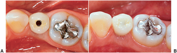
FIGURE 14-51 A, Occlusal view of a single-tooth implant crown replacing a fractured mandibular premolar. B, Implant crown with screw access restored. (Rosenstiel SF, Land MF, Fujimoto J: Contemporary fixed prosthodontics, ed 4, St Louis, 2006, Mosby.)
Implant survival depends on proper and timely home care and maintenance. The dentist must ensure that the patient receives thorough instruction in maintenance techniques. The goal of implant maintenance is to eradicate microbial populations. Recall visits should be scheduled at least every 3 months for the first year. The sulcular area should be débrided of calculus by using plastic or wooden scalers. A rubber cup with low abrasive polishing paste or tin oxide may be used to polish implant abutments. Implant mobility should be evaluated, and bleeding upon probing should be documented. Framework fit and occlusion should also be checked at recall appointments. These biomechanical factors are as important as oral hygiene for the long-term success of the dental implant.
Failing Implant
Implant failure occurs at three distinct times: (1) at the time of (or shortly after) stage II surgery, (2) approximately 18 months after stage II surgery, and (3) more than 18 months after stage II surgery.
A few implants fail to integrate. This failure often is identified at the time of (or shortly after) stage II surgery. Failure in this period may be related to a variety of factors. Overheating of the bone during placement or failure to achieve a precise implant fit with primary stability may lead to failure of integration. Postoperative infection, excessive pressure on the integrating implant (with movement of the implant), or wound-healing problems may also jeopardize implant integration.
After loading with a prosthesis, bone loss occurs for approximately 18 months, after which time a steady state will be achieved. During this 18-month period, additional implant failure may occur. Failure in this period is often associated with excessive biomechanical forces on the implant or compromised periimplant soft tissue health resulting from lack of attached tissue, poor hygiene, or both. Smoking is also associated with increased failure in this period and later periods. Late failure (i.e., more than 18 months after placement of the prosthesis) may also occur. This is rare, and frequently the cause is not identifiable. In general, these implants are identified as “ailing” during routine recall. Progressive bone loss in spite of rigorous hygiene measures is often seen. A combined prosthodontic and surgical intervention can often restore health to these ailing implants.
Once periimplant bone loss has been identified, efforts should initially be focused on optimizing hygiene. This may even require removal of the prosthesis to facilitate access. If bone loss is severe or progressive, surgical intervention is necessary. The implant must be exposed surgically and all soft tissue adjacent to the implant surface removed. The surface of the implant is then cleaned with hydrogen peroxide, after which citric acid is used. Tetracycline powder can be placed along the implant surface and into the bony defect, and the defect can be reconstructed with a graft. Healing for a minimum of 4 months is allowed, after which the implant is uncovered and the prosthesis is replaced.
ADVANCED SURGICAL TECHNIQUES
Guided bone regeneration is a process that allows bone growth while retarding the ingrowth of fibrous connective tissue and epithelium. Most bone defects will regenerate with new bone if the invasion of connective tissue from adjacent soft tissue can be prevented. Guided bone regeneration uses a barrier that is placed over the bone defect and prevents fibrous tissue ingrowth while the bone underlying the barrier has time to grow and fill the defect (Fig. 14-52). This technique is particularly useful in the treatment of buccal dehiscence, where labiobuccal augmentation of bone is required. Guided bone regeneration can be performed simultaneously with implant placement or before stage I. A variety of materials may serve as barriers to fibrous tissue ingrowth. Ideal characteristics of a membrane are outlined in Box 14-7. Expanded polytetrafluoroethylene (Gore-Tex) is the most extensively tested material. Resorbable materials are also now available, eliminating the necessity of removal.
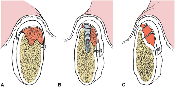
FIGURE 14-52 Various applications of guided bone regeneration. A, Membrane and “filler material” such as allogeneic bone is used to augment the ridge. B, Same as in A except that an implant is placed simultaneously. C, The membrane is supported by screws that preserve the space beneath the graft to allow bone fill.
Block Bone Grafting
Guided bone regeneration is most often used for lateral ridge augmentation. Some authors have described vertical augmentation, but it is less predictable.
Corticocancellous bone grafts are an alternative to guided bone regeneration techniques. Bone can be harvested from the genial region, mandibular ramus, or iliac crest and used to augment lateral or vertical height of the atrophic ridge (Fig. 14-53). The defect is approached and prepared for grafting by perforating the cortical bone and creating a site to receive the graft. The corticocancellous block is harvested and trimmed to fit into the defect. Stabilization of the graft and primary closure is paramount. After 4 to 6 months of healing, the implant surgery can be accomplished (Fig. 14-54).
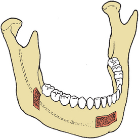
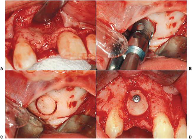
FIGURE 14-54 A, A bony defect is suspected in the anterior maxilla caused by congenitally missing lateral incisor. B, View of the defect after the bone is exposed. C, Harvest of a cortical cancellous bone graft from the genial region with a trephine. D, The graft is placed and stabilized with a screw.
Alveolar Distraction
All grafting techniques are compromised when inadequate soft tissue is present. This is particularly problematic in the anterior maxilla when vertical hard and soft tissue defects exist after trauma or treatment of a pathologic condition. Tightly bound tissue in this area makes primary closure difficult. Distraction osteogenesis techniques take advantage of the development of bone that results when an osteotomized segment of bone is slowly moved, allowing new bone formation within the gap. This technique was initially used to lengthen long bones, but the principles have been applied to the jaws and to alveolar bone (also refer to Chapters 13 and 25). The technique has the disadvantage of increased cost associated with the distraction device and esthetic compromise during the distraction phase. However, it is a predictable way to gain large vertical increases of soft and hard tissue, especially in difficult areas such as the anterior maxilla (Fig. 14-55).
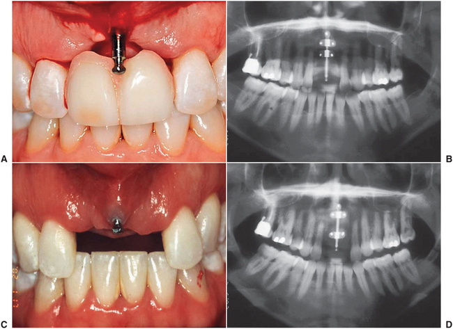
Transantral Grafting (Sinus Lift)
After tooth loss, alveolar resorption occurs. In the posterior maxilla, crestal bone resorption is also accompanied by sinus pneumatization. In situations in which inadequate bone exists to place implants of appropriate length, sinus floor augmentation can be performed. This can be done indirectly through the implant osteotomy site or directly by an approach through the lateral wall of the maxillary sinus.
When only a few millimeters of augmentation is needed in conjunction with simultaneous implant placement, indirect sinus lift is effective. This procedure relies on the lack of density found in maxillary cancellous bone. The initial drill is used to locate the angulation and position of the planned implant. The depth is drilled just short of the sinus floor. Osteotomes are then used to enlarge the site progressively. The osteotome is cupped on the end and compresses the walls of the osteotomy site; it also scrapes bone from the sides of the wall, pushing it ahead. The bone of the sinus floor is pushed upward, elevating the sinus membrane and depositing the bone from the lateral wall of the osteotomy into the sinus below the membrane (Fig. 14-56). If needed, additional graft material can be introduced through the implant site.
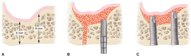
FIGURE 14-56 Indirect sinus elevation procedure. A, Pneumatized sinus with adequate bone for primary stability. B, After drilling pilot holes, osteotomes are used to enlarge the osteotomy while placing graft material. C, The pressure created by the graft material as it is inserted into the osteotomy expands the intact sinus membrane and elevates the floor of the sinus, allowing implant placement.
Undetected perforation may occur with this technique. This procedure is only possible when a few millimeters of bone are needed for an implant that has adequate primary stability in native bone.
If several implants are to be placed or more than 4 to 5 mm of augmentation is needed, a direct approach is required. A window is created in the lateral wall of the sinus, the sinus membrane is elevated, and the floor is grafted to increase vertical bone height (Fig. 14-57). Implants may be placed simultaneously with the grafting procedure if adequate native bone is present for primary implant stability. This is usually defined as 4 mm or more of bone. If less than 4 mm of bone is available, the procedure should be staged with initial grafting alone, after which the graft is consolidated and the implant is placed. Transantral grafting (i.e., sinus lift) procedures can be performed in an outpatient setting using autogenous bone, allogeneic bone, or bone substitutes. Success is similar for all these materials. Autogenous bone requires less time than allogeneic or xenogeneic bone to consolidate (4 to 6 months versus 7 to 12 months).
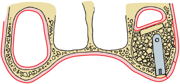
The available bone to support the implant can be significantly improved with these techniques. Patients who smoke have a significant increased failure rate, and some authors suggest that smoking is a contraindication to sinus lift. In addition, a much higher incidence of infection after this procedure is found than with other implant surgery. Antibiotic prophylaxis is paramount. Patients must also refrain from wearing a prosthesis over the surgical area for a minimum of 1 week.
SPECIAL SITUATIONS
Postextraction Placement of Implants
When implant placement is planned before extraction of the tooth, consideration should be given to the most desirable time for implant placement. The implant may be placed immediately (i.e., at the time of extraction), early (i.e., 2 months after extraction), or late (i.e., more than 6 months after extraction). Each of these times has its indications, advantages, and disadvantages.
Immediate placement allows the overall shortest healing time and combines the tooth extraction with the surgical implant placement. Immediate placement can be considered if the tooth to be removed is not infected and can be removed without the loss of alveolar bone. Once the tooth is removed, the implant is placed at least 4 mm apical to the apex of the tooth (Fig. 14-58). The implant should be countersunk slightly below the height of the crestal bone to allow for resorption of the bone resulting from extraction.
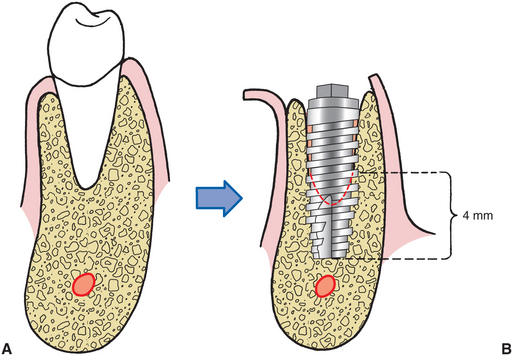
FIGURE 14-58 Implants placed in fresh extraction sockets must have 4 mm of precise fit along apical aspect of implant. Implants should be countersunk slightly below the crest of bone, and any gap between sides of extraction socket and implant should be less than 1 mm. If the gap is greater than 1 mm, grafting with a scientifically validated particulate graft material of the surgeon’s choice should be considered.
The gap between the implant and the residual tooth socket must be evaluated and managed according to its size. If the gap is less than 1 mm, no treatment modification is needed. If the gap is greater than 1 mm, grafting with a particulate material may be necessary.
After implant placement, every effort should be made to achieve a primary soft tissue closure. If this is not possible, a resorbable collagen pellet may be placed over the implant and held in place with a figure-of-eight suture. The surgeon may consider extending the time allowed for integration before loading.
Anterior Maxilla Esthetic Zone
In the esthetic zone of the anterior maxilla, successful integration alone is not adequate. The implant must have proper position, angulation, and depth for esthetic restoration. These parameters are prosthodontically determined and communicated to the surgeon by the surgical stent. The stent must show the ideal position; labial thickness of porcelain and metal; and location of the cementoenamel junction of the final prosthesis. If inadequate bone is present to place the implant with proper position and angulation, grafting is necessary. Esthetic concerns and compromised bone often present in the situation of congenitally missing teeth. Failure of tooth formation is associated with severe hypoplasia of the alveolar bone. Grafting using guided bone regeneration techniques or corticocancellous blocks must be considered (see Fig. 14-54). Implant depth is also important to allow proper emergence profile. Excessive depth leads to increased pocket depth, and too shallow placement can result in a poorly contoured crown or metal showing at the gingival margin. As a general rule, the top of the implant should be placed 3 mm below the planned position of the cementoenamel junction of the final restoration.
Atrophic Anterior Mandible
In the atrophic mandible (i.e., less than 8 mm of vertical height), the shortest implant may be longer than the available bone. Implants may be placed by purposefully perforating the inferior cortex. This may decrease the crown-to-root ratio or increase the risk of fracture. Recent studies have shown that after restoration of the atrophic mandible with an entirely implant-supported prosthesis, bone height and density increase, presumably as a result of the functional stresses that result from the prosthesis.
Therefore an effective approach in the atrophic mandible is to place five implants, leaving 2 to 3 mm above the height of the residual bone. An entirely implant-supported hybrid prosthesis is then fabricated. Alternatively, the transmandibular implant has also been shown to be effective in the atrophic mandible, with similar remodeling and formation of new bone. Either of these techniques may be considered in the atrophic mandible where 6 mm or more of bone height is found. If the bone height is less than 6 mm, augmentation of the bony height in this area with autogenous grafts may be necessary. Autogenous grafts onlayed onto the residual ridge undergo resorption if conventional dentures are placed but are generally maintained well if an implant-borne prosthesis is placed.
Atrophic Posterior Mandible
As discussed before, the posterior mandible poses unique problems. Presence of the inferior alveolar nerve limits implant length. This, coupled with increased occlusal load, is one reason for the higher implant failure rate in this region. Overengineering with placement of more implants can improve the prognosis. When less than 8 mm of vertical height overlying the inferior alveolar nerve is found, implant success will be severely compromised. Bone may be grafted to increase height as previously described.
However, if supereruption of the posterior maxillary dentition exists, a graft of adequate thickness to improve implant stability may result in inadequate interarch space for the prosthesis. In this case the inferior alveolar nerve may be repositioned to allow use of the entire height of the mandibular body (Fig. 14-59). This procedure carries the risk of permanent anesthesia or painful dysesthesia. The magnitude of this complication requires that a surgeon experienced with nerve surgery and postoperative assessment of neurosensory function perform this operation. The advantage is that with repositioning of the nerve, a longer implant can be placed, with stabilization in the superior and inferior cortical bone.
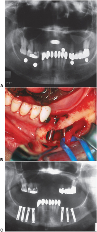
FIGURE 14-59 A, Panoramic radiograph reveals supereruption of the posterior maxillary dentition with loss of interarch space. Inadequate room for implants above the inferior alveolar nerve and no room for a graft is found. B, The inferior alveolar nerve is positioned buccally to allow implants to be placed. C, Postoperative panoramic radiograph shows implants of adequate length extending to the inferior border.
Atrophic Maxilla
Initial implant restorative approaches for the fully edentulous maxilla concentrated on implant placement in the anterior region, similar to the edentulous mandible. However, the resulting prosthesis was often unsatisfactory. If adequate space was allowed for proper hygiene, phonetics and esthetics were severely compromised. If the prosthesis was developed in such a way as to eliminate these problems, hygiene became virtually impossible. The cantilever effect of this type of prosthesis on implants placed within the compromised bone of the maxilla also resulted in increased failures. If implants are placed bilaterally in the posterior maxilla, a prosthesis with ideal esthetics, phonetics, and hygiene access can be created. However, the bone overlying the sinus is frequently inadequate to place the implant and to allow suitable bony support. In these situations the sinus floor may be grafted to increase the quantity of bone for implant placement.
Some patients are unwilling to wait the time required for sinus lift consolidation or are unwilling to undergo grafting. A relatively new technique that places very long implants into the body of the zygoma (Zygomaticus system), along with short anterior implants, is an effective way to support a maxillary overdenture without need for sinus lift surgery (Fig. 14-60).
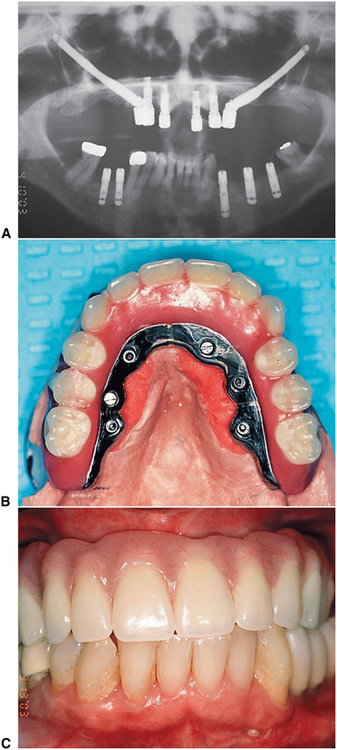
Implants in Growing Patients
Children may have edentulous spaces resulting from congenital absence of teeth or loss of teeth from trauma, infection, or neoplasia. The ability to restore the lost function without damage to adjacent virgin teeth that would occur from conventional restorative methods is appealing. Evidence suggests that implants can be successfully placed into growing patients. In the fully edentulous patient, an implant-supported prosthesis can be fabricated as soon as the patient is old enough to cooperate with hygiene requirements. This is usually defined as age 7. In patients who have lost a portion of the jaw from tumor resection or trauma, an implant-supported prosthesis can likewise be used as early as age 7. However, when the edentulous area in question is associated with unerupted natural teeth, no implants should be placed until eruption of the natural dentition and alveolar growth are complete (i.e., at approximately 16 years of age). Implants placed before this time behave in similar fashion to an ankylosed tooth, with progressive submersion of the implant as a result of eruption of adjacent teeth and alveolar bone growth.
Implants in Irradiated Bone
Cancer patients frequently suffer from surgery- and irradiation-associated soft and hard tissue defects that significantly compromise conventional prosthodontic rehabilitation. An implant-supported prosthesis could improve function and esthetics; however, concern regarding the compromised wound healing that results after tumoricidal irradiation to the jaws has contraindicated even minor surgery and implant placement in these patients. It now appears that it may be possible to place implants in this group of patients (see Chapter 18). Careful soft tissue handling and perioperative hyperbaric oxygen treatments have been used for patients receiving implants in irradiated tissue, with results comparable to that found in nonirradiated patients. Little is known about the long-term results in these patients, and potential for increased failure and serious sequelae (e.g., osteoradionecrosis) still exists. As a result, an experienced implant surgeon should manage implant placement in this group of patients.
Early Loading
Since staged implant systems were first introduced, there have been efforts to define the minimum time required for osseointegration. Generally accepted integration times are based on experience and tradition with little experimental data. Research continues to attempt to define ideal minimum integration times. Factors that are likely important in determining what these minimum times should be include bone quality, implant material, and surface and prosthesis configuration. Some studies have shown that early loading (i.e., 6 weeks) is successful, even in typically difficult areas such as the posterior mandible. Clearly, there are more variables to consider in these cases, and not all patients or restorative situations are amenable. The most extreme variation on the theme of early loading is immediate loading. There are emerging data to suggest that immediate loading of implants in controlled situations can be successful as well. Initial primary stability, good bone, controlled occlusal forces, and patient compliance are factors that must be considered.
Extraoral Implants
Recognizing the success of implants for oral applications, maxillofacial prosthodontists and surgeons have expanded use of titanium fixtures to extraoral application. Extraoral implants are now used to anchor prosthetic ears, eyes, and noses for patients with defects resulting from congenital conditions, trauma, or pathologic conditions (Fig. 14-61).
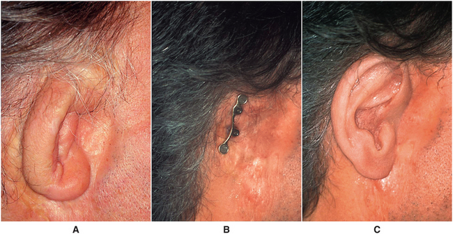
Bibliography
Adell, R. Long-term treatment results. In: Branemark PI, Zarb G, Albrektson I, eds. Tissue-integrated prostheses. Chicago: Quintessence, 1985.
Adell, R, Lekholm, U, Rockler, B, et al. A 15-year study of osseointegrated implants in the treatment of the edentulous jaw. Int J Oral Surg. 1981;10:387.
Bain, CA, May, PK. The association between the failure of dental implants and cigarette smoking. Int J Oral Maxillofac Implants. 1993;8:609.
Dahlin, C, Sennerby, L, Lekholm, U, et al. Generation of new bone around titanium implants using a membrane technique: an experimental study in rabbits. Int J Oral Maxillofac Implants. 1989;4:19.
Eriksson, AR, Albrektsson, T. Temperature threshold levels for heat-induced bone tissue injury: a vital microscopic study in the rabbit. J Prosthet Dent. 1983;50:101.
Granström, G, Bergström, K, Tjellström, A, et al. A detailed analysis of titanium implants lost in irradiated tissue. Int J Oral Maxillofac Implants. 1994;9:653.
Jensen, OT, Shulman, LB, Block, MS, et al. Report of the Sinus Consensus Conference of 1996. Int J Oral Maxillofac Implants. 1998;13:11–41.
Lazzara, RJ. Immediate implant placement into extraction sites: surgical and restorative advantages. Int J Periodontics Restorative Dent. 1989;9:333.
McKinney, RV, Steflik, DE, Roth, DL. The biologic response to single crystal sapphire endosteal implant: SEM observations. J Prosthet Dent. 1984;51:372.
Perrott, DH, Shama, AB, Vargerik, K. Endosseous implants for pediatric patients. Oral Maxillofac Clin N Am. 1994;6:79.
Peterson, LJ, McGlumphy, EA, Larsen, PE, et al. Comparison of mandibular bone response to implant overdentures versus implant-supported hybrid. J Dent Res. 1996;75:333.
Peterson, LJ, Larsen, PE, McGlumphy, EA, et al. Long-term antibiotic prophylaxis is not necessary for placement of dental implants. J Oral Maxillofac Surg. 1996;54(suppl 3):76.
Quirynen, M, Alsaadi, G, Pauwels, M, et al. Microbiological and clinical outcomes and patient satisfaction for two treatment options in the edentulous lower jaw after 10 years of function. Clin Oral Implants Res. 2005;16:277–287.
Rosen, PS, Summers, R, Mellado, JR, et al. PA. The bone-added osteotome sinus floor elevation technique: multicenter retrospective report of consecutively treated patients. Int J Oral Maxillofac Implants. 1999;14:853–858.
Sammartino, G, Marenzi, G, di Lauro, AE, et al. Aesthetics in oral implantology: biological, clinical, surgical, and prosthetic aspects. Implant Dent. 2007;16:54–65.
Sclar, AG. Strategies for management of single-tooth extraction sites in aesthetic implant therapy. J Oral Maxillofac Surg. 2004;62(9 suppl 2):90–105.
Smith, D, Zarb, GA. Criteria for success for osseointegrated endosseous implants. J Prosthet Dent. 1989;62:567.
Stanford, CM. Application of oral implants to the general dental practice. J Am Dent Assoc. 2005;36:1092–1100.
Tarnow, DP, Magner, AW, Fletcher, P. The effect of the distance from the contact point to the crest of gone on the presence or absence of the interproximal dental papilla. J Periodontol. 1992;63:995–996.
U.S. Department of Health and Human Services: Dental implants, NIH Consensus Development Conference Statement, 7:108.
Veksler, AE, Kayrouz, GA, Newman, MG. Chlorhexidine reduces salivary bacteria during scaling and root planing. J Dent Res. 1990;69:240.
Woo, SB, Hellstein, JW, Kalmar, JR. Systematic review: bisphosphonates and osteonecrosis of the jaws. Ann Intern Med. 2006;144:753–761.