The X-ray Imaging System
At the completion of this chapter, the student should be able to do the following:
1 Identify the components of the x-ray imaging system operating console.
2 Explain the operation of the high-voltage generator.
3 Relate the differences among single-phase, three-phase, and high-frequency power.
4 Discuss the importance of voltage ripple to x-ray quantity and quality.
WHEN FAST-MOVING electrons slam into a metal object, x-rays are produced. The kinetic energy of the electrons is transformed into electromagnetic energy. The function of the x-ray imaging system is to provide a controlled flow of electrons intense enough to produce an x-ray beam appropriate for imaging.
The three main components of an x-ray imaging system are (1) the x-ray tube, (2) the operating console, and (3) the high-voltage generator. The x-ray tube is discussed in Chapter 6. This chapter describes the components of the operating console that are used to control the voltage applied to the x-ray tube, the current through the x-ray tube, and the exposure time.
This chapter also discusses the high-voltage generator in its many forms. The high-voltage generator contains the high-voltage step-up transformer and the rectification circuit. The final section of this chapter combines all components into a single complete circuit diagram.
The many different types of x-ray imaging systems are usually identified according to the energy of the x-rays they produce or the purpose for which the x-rays are intended. Diagnostic x-ray imaging systems come in many different shapes and sizes, some of which are shown in Figure 5-1. These systems are usually operated at voltages of 25 to 150 kVp and at tube currents of 100 to 1200 mA.
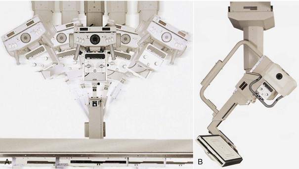
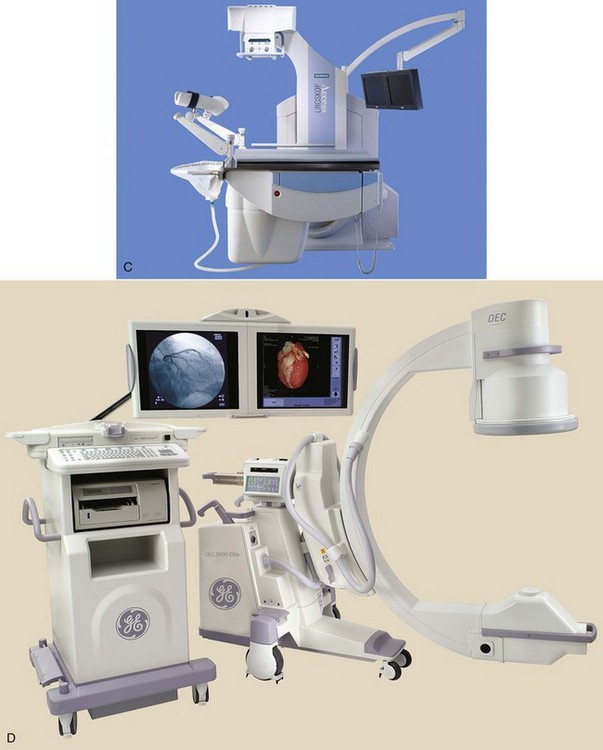
FIGURE 5-1 Types of diagnostic x-ray imaging systems. A, Tomographic. B, Trauma. C, Urologic. D, Mobile. (C, Courtesy Siemens Medical Systems.)
The general purpose x-ray examination room contains a radiographic imaging system and a fluoroscopic imaging system. The fluoroscopic x-ray tube is usually located under the examining table; the radiographic x-ray tube is attached to an overhead movable crane assembly that permits easy positioning of the tube and aiming of the x-ray beam.
This type of equipment can be used for nearly all radiographic and fluoroscopic examinations. Rooms with a fluoroscope and two or more overhead radiographic tubes are used for special radiology interventional applications.
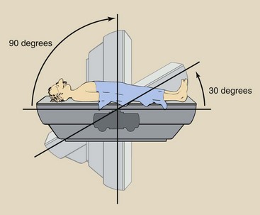
Regardless of the type of x-ray imaging system used, a patient-supporting examination couch is required (Figure 5-2). This examination couch may be flat or curved but must be uniform in thickness and as transparent to x-rays as possible. Carbon fiber couches are strong and absorb little x-radiation. This contributes to reduced patient radiation dose.
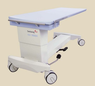
Most patient couches are floating—easily unlocked and moved by the radiologic technologist—or motor-driven. Just under the couch is an opening to hold a thin tray for a cassette and grid. If the couch is used for fluoroscopy, the tray must move to the foot of the couch, and the opening must be automatically shielded for radiation protection with a Bucky slot cover. Fluoroscopic couches tilt and are identified by their degrees of tilt. For example, a table would tilt 90 degrees to the foot side and 30 degrees to the head side (Figure 5-3).
| Question: | How far below horizontal will a patient’s head go on a fluoroscopic couch? |
| Answer: | 30 degrees below horizontal |
Regardless of its design, every x-ray imaging system has three principal parts: the x-ray tube (see Chapter 6), the operating console, and the high-voltage generator. In some types of x-ray imaging systems, such as dental and portable machines, these three components are housed compactly. With most systems, however, the x-ray tube is located in the examination room, and the operating console is located in an adjoining room with a protective barrier separating the two.
The protective barrier must have a window for viewing the patient during the examination. Ideally, the room should be designed so that it is possible to reach the operating console without having to enter the “radiation area” of the examination room.
The high-voltage generator may be housed in an equipment cabinet positioned against a wall. The high-voltage generator is always close to the x-ray tube, usually in the examination room. A few installations take advantage of false ceilings and place these generators out of sight above the examination room.
Newer generator designs that use high-frequency circuits require even less space. Figure 5-4 is a plan drawing of a conventional, general-purpose x-ray examination room.
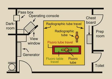
FIGURE 5-4 Plan drawing of a general-purpose x-ray examination room, showing locations of the various x-ray apparatus items. Chapter 38 considers the layout of such rooms in greater detail.
Operating Console
The part of the x-ray imaging system most familiar to radiologic technologists is the operating console. The operating console allows radiologic technologists to control the x-ray tube current and voltage so that the useful x-ray beam is of proper quantity and quality (Figure 5-5).
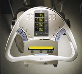
FIGURE 5-5 Typical operating console to control an overhead radiographic imaging system. Numbers of meters and controls depend on the complexity of the console.
Radiation quantity refers to the number of x-rays or the intensity of the x-ray beam. Radiation quantity is usually expressed in milligray (mGya) or milligray/milliampere-second (mGya/mAs). Radiation quality refers to the penetrability of the x-ray beam and is expressed in kilovolt peak (kVp) or, more precisely, half-value layer (HVL) (see Chapter 8).
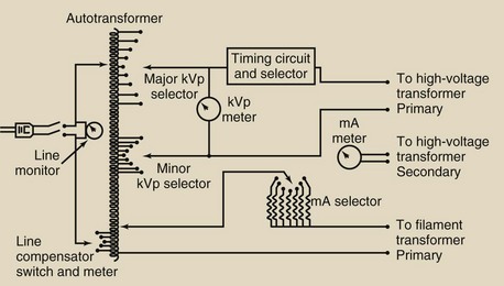
The operating console usually provides for control of line compensation, kVp, mA, and exposure time. Meters are provided for monitoring kVp, mA, and exposure time. Some consoles also provide a meter for mAs. Imaging systems that incorporate automatic exposure control (AEC) may have separate controls for mAs.
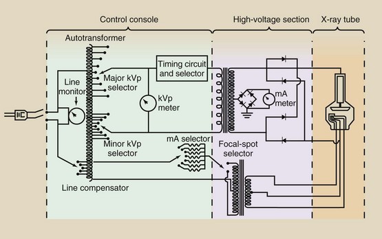
All of the electric circuits that connect the meters and controls on the operating console are at low voltage to minimize the possibility of hazardous shock. Figure 5-6 is a simplified schematic diagram for a typical operating console. A look inside an operating console will indicate how simplified this schematic drawing is!
Operating consoles are based on computer technology. Controls and meters are digital, and techniques are selected with a touch screen. Numeric technique selection is often replaced by icons indicating the body part, size, and shape. Many of the features are automatic, but the radiologic technologist must know their purpose and proper use.
Most x-ray imaging systems are designed to operate on 220 V power, although some can operate on 110 V or 440 V. Unfortunately, electric power companies are not capable of providing 220 V accurately and continuously.
Because of variations in power distribution to the hospital and in power consumption by various sections of the hospital, the voltage provided to an x-ray unit easily may vary by as much as 5%. Such variation in supply voltage results in a large variation in the x-ray beam, which is inconsistent with production of high-quality images.
The line compensator measures the voltage provided to the x-ray imaging system and adjusts that voltage to precisely 220 V. Older units required technologists to adjust the supply voltage while observing a line voltage meter. Today’s x-ray imaging systems have automatic line compensation and hence have no meter.
Autotransformer
The power supplied to the x-ray imaging system is delivered first to the autotransformer. The voltage supplied from the autotransformer to the high-voltage transformer is controlled but variable. It is much safer and easier to control a low voltage and then increase it than to increase a low voltage to the kilovolt level and then control its magnitude.
 The autotransformer has a single winding and is designed to supply a precise voltage to the filament circuit and to the high-voltage circuit of the x-ray imaging system.
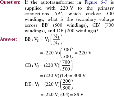
The autotransformer works on the principle of electromagnetic induction but is very different from the conventional transformer. It has only one winding and one core. This single winding has a number of connections along its length (Figure 5-7). Two of the connections, A and A′ as shown in the figure, conduct the input power to the autotransformer and are called primary connections.
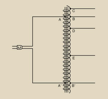
Some of the secondary connections, such as C in the figure, are located closer to one end of the winding than are the primary connections. This allows the autotransformer to increase voltage. Other connections, such as D and E in the figure, allow a decrease in voltage. The autotransformer can be designed to step up voltage to approximately twice the input voltage value.
Because the autotransformer operates as an induction device, the voltage it receives (the primary voltage) and the voltage it provides (the secondary voltage) are related directly to the number of turns of the transformer enclosed by the respective connections. The autotransformer law is the same as the transformer law.
 Autotransformer Law

NP = the number of windings enclosed by primary connections
NS = the number of windings enclosed by secondary connections
Adjustment of Kilovolt Peak (kVp)
Some older x-ray operating consoles have adjustment controls labeled major kVp and minor kVp; by selecting a combination of these controls, radiologic technologists can provide precisely the required kilovolt peak. The minor kilovolt peak adjustment “fine tunes” the selected technique. The major kilovolt peak adjustment and the minor kilovolt peak adjustment represent two separate series of connections on the autotransformer.
Appropriate connections can be selected with an adjustment knob, a push button, or a touch screen. If the primary voltage to the autotransformer is 220 V, the output of the autotransformer is usually controllable from about 100 to 400. This low voltage from the autotransformer becomes the input to the high-voltage step-up transformer that increases the voltage to the chosen kilovolt peak.
The kVp meter is placed across the output terminals of the autotransformer and therefore actually reads voltage, not kVp. The scale of the kVp meter, however, registers kilovolts because of the known multiplication factor of the turns ratio.
On most operating consoles, the kVp meter registers, even though no exposure is being made and the circuit has no current. This type of meter is known as a prereading kVp meter. It allows the voltage to be monitored before an exposure.
Control of Milliamperage (mA)
The x-ray tube current, crossing from cathode to anode, is measured in milliamperes (mA). The number of electrons emitted by the filament is determined by the temperature of the filament.
The filament temperature is in turn controlled by the filament current, which is measured in amperes (A). As filament current increases, the filament becomes hotter, and more electrons are released by thermionic emission. Filaments normally operate at currents of 3 to 6 A.
A correction circuit has to be incorporated to counteract the space charge effect. As the kVp is raised, the anode becomes more attractive to the electrons that would not have enough energy to leave the filament area. These electrons also join the electron stream, which effectively increases the mA with kVp.
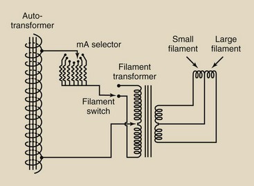
X-ray tube current is controlled through a separate circuit called the filament circuit (Figure 5-8). Connections on the autotransformer provide voltage for the filament circuit. Precision resistors are used to reduce this voltage to a value that corresponds to the selected milliamperage.
X-ray tube current normally is not continuously variable. Precision resistors result in fixed stations that provide tube currents of 100, 200, or 300 mA, and higher.
The falling load generator constitutes an exception. In a falling load generator, the exposure begins at maximum mA, and the mA drops as the anode heats. The result is minimum exposure time.
The product of x-ray tube current (mA) and exposure time(s) is mAs, which is also electrostatic charge (C).
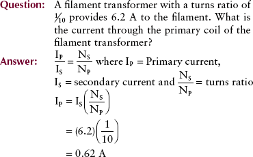
The voltage from the mA selector switch is then delivered to the filament transformer. The filament transformer is a step-down transformer; therefore, the voltage supplied to the filament is lower (by a factor equal to the turns ratio) than the voltage supplied to the filament transformer. Similarly, the current is increased across the filament transformer in proportion to the turns ratio.
X-ray tube current is monitored with an mA meter that is placed in the tube circuit. The mA meter is connected at the center of the secondary winding of the high-voltage step-up transformer. The secondary voltage is alternating at 60 Hz such that the center of this winding is always at zero volts (Figure 5-9).
FIGURE 5-9 The mA meter is in the x-ray tube circuit at a center tap on the output of the high-voltage step-up transformer. This ensures electrical safety.
In this way, no part of the meter is in contact with the high voltage, and the meter may be safely put on the operating console. Sometimes this meter allows that mAs can be monitored in addition to mA.
Filament Transformer
The full title for this transformer is the filament heating isolation step-down transformer. It steps down the voltage to approximately 12 V and provides the current to heat the filament. Because the secondary windings are connected to the high-voltage supply for the x-ray tube, the secondary windings are heavily insulated from the primary.
In the filament transformer, the primary windings are of thin copper and carry a current of 0.5 to 1 A and approximately 150 V. The secondary windings are thick and at approximately 12 V electric potential and carry a current of 5 to 8 A (not mA!).
Exposure Timers
For any given radiographic examination, the number of x-rays that reach the image receptor is directly related to both the x-ray tube current and the time that the x-ray tube is energized. X-ray operating consoles provide a wide selection of x-ray beam-on times and, when used in conjunction with the appropriate mA station, provide an even wider selection of values for mAs.
Paramount in the design of all timing circuits is that the radiographer starts the exposure and the timer stops it. During fluoroscopy, if the radiographer releases the exposure switch or the fluoroscopic foot switch, the exposure is terminated immediately.
As an additional safety feature, another timing circuit is activated on every radiographic exposure. This timer, called a guard timer, will terminate an exposure after a prescribed time, usually approximately 6 s. Thus, it is not possible for any timing circuit to continuously irradiate a patient for an extensive period.
The timer circuit is separate from the other main circuits of the x-ray imaging system. It consists of an electronic device whose action is to “make” and “break” the high voltage across the x-ray tube. This is nearly always done on the primary side of the high-voltage transformer, where the voltage is lower.
There are four types of timing circuits. Three are controlled by the radiologic technologist, and one is automatic. After studying this section, try to identify the types of timers on the equipment you use.
Synchronous Timers
In the United States, electric current is supplied at a frequency of 60 Hz. In Europe, Latin America, and other parts of the world, the frequency is 50 Hz. A special type of electric motor, known as a synchronous motor, is a precision device designed to drive a shaft at precisely 60 revolutions per second (rps). In some x-ray imaging systems, synchronous motors are used as timing mechanisms.
X-ray imaging systems with synchronous timers are recognizable because the minimum exposure time possible is 1/60 s (17 ms), and timing intervals increase by multiples thereof, such as, 1/30, 1/20, and so on. Synchronous timers cannot be used for serial exposures because they must be reset after each exposure.
Electronic Timers
Electronic timers are the most sophisticated, most complicated, and most accurate of the x-ray exposure timers. Electronic timers consist of rather complex circuitry based on the time required to charge a capacitor through a variable resistance.
Electronic timers allow a wide range of time intervals to be selected and are accurate to intervals as small as 1 ms. Because they can be used for rapid serial exposures, they are particularly suitable for interventional radiology procedures.
mAs Timers
Most x-ray apparatus is designed for accurate control of tube current and exposure time. However, the product of mA and time—mAs—determines the number of x-rays emitted and therefore the exposure of the image receptor. A special kind of electronic timer, called an mAs timer, monitors the product of mA and exposure time and terminates exposure when the desired mAs value is attained.
The mAs timer is usually designed to provide the highest safe tube current for the shortest exposure for any mAs selected. Because the mAs timer must monitor the actual tube current, it is located on the secondary side of the high-voltage transformer.
Automatic Exposure Control
The AEC requires a special understanding on the part of the radiologic technologist. The AEC is a device that measures the quantity of radiation that reaches the image receptor. It automatically terminates the exposure when the image receptor has received the required radiation intensity. Figure 5-10 shows two types of AEC design.
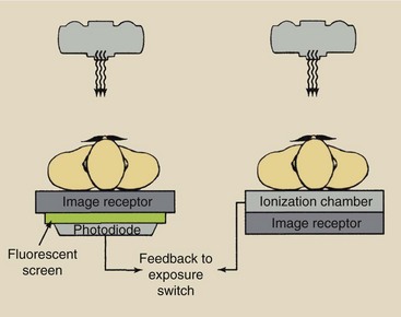
FIGURE 5-10 Automatic exposure control terminates the x-ray exposure at the desired film optical density. This is done with an ionization chamber or a photodiode detector assembly.
The type of AEC used by most manufacturers incorporates a flat, parallel plate ionization chamber positioned between the patient and the image receptor. This chamber is made radiolucent so that it will not interfere with the radiographic image. Ionization within the chamber creates a charge. When the appropriate charge has been reached, the exposure is terminated.
When an AEC x-ray imaging system is installed, it must be calibrated. This calls for making exposures of a test object and adjusting the AEC for the range of x-ray intensities required for quality images. The service engineer usually takes care of this calibration.
After the AEC is in clinical operation, the radiologic technologist selects the type of examination, which then sets the appropriate mA and kVp. At the same time, the exposure timer is set to the backup time. When the electric charge from the ionization chamber reaches a preset level, a signal is returned to the operating console, where the exposure is terminated.
The AEC is now widely used and often is provided in addition to an electronic timer. The AEC mode requires particular care, especially in examinations that use low kVp such as mammography. Because of varying tissue thickness and composition, the AEC may not respond properly at low kVp.
When radiographs are taken in the AEC mode, the electronic timer should be set to 1.5 times the expected exposure time as a backup timer in case the AEC fails to terminate. This precaution should be followed for the protection of the patient and the x-ray tube. Many units automatically set this precaution.
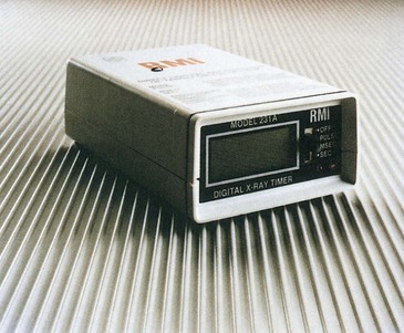
Solid-state radiation detectors are now used for exposure-timer checks (Figure 5-11). These devices operate with a very accurate internal clock based on a quartz-crystal oscillator. They can measure exposure times as short as 1 ms and, when used with an oscilloscope, can display the radiation waveform.
High-Voltage Generator
The high-voltage generator of an x-ray imaging system is responsible for increasing the output voltage from the autotransformer to the kVp necessary for x-ray production. A cutaway view of a typical high-voltage generator is shown in Figure 5-12. Although some heat is generated in the high-voltage section and is conducted to oil, the oil is used primarily for electrical insulation.
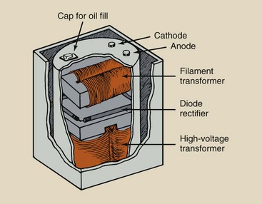
FIGURE 5-12 Cutaway view of a typical high-voltage generator showing oil-immersed diodes and transformers.
The high-voltage generator contains three primary parts: the high-voltage transformer, the filament transformer, and rectifiers.
High-Voltage Transformer
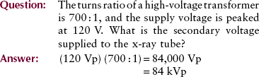
The high voltage transformer is a step-up transformer, that is, the secondary voltage is higher than the primary voltage because the number of secondary windings is greater than the number of primary windings. The ratio of the number of secondary windings to the number of primary windings is called the turns ratio (see Chapter 4). The voltage increase is proportional to the turns ratio, according to the transformer law. Also, the current is reduced proportionately.
The turns ratio of a high-voltage transformer is usually between 500 : 1 and 1000 : 1. Because transformers operate only on alternating current, the voltage waveform on both sides of a high-voltage transformer is sinusoidal (Figure 5-13). The only difference between the primary and secondary waveforms is their amplitude. The primary voltage is measured in volts (V), and the secondary voltage is measured in kilovolts (kV). The primary current is measured in amperes (A), and the secondary current is measured in milliamperes (mA).
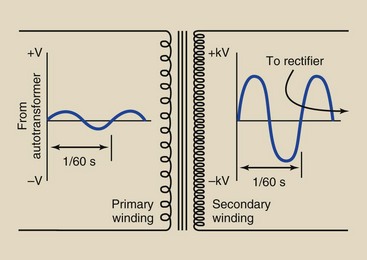
FIGURE 5-13 Voltage induced in the secondary winding of a high-voltage step-up transformer is alternating like the primary voltage but has a higher value.
Voltage Rectification
The current from a common wall plug is 60 Hz alternating current (AC). The current changes direction 120 times each second. However, an x-ray tube requires a direct current (DC), that is, electron flow in only one direction. Therefore, some means must be provided for converting AC to DC.
In the case of 50 Hz power, there are 100 half-cycles per second, each lasting 10 ms. In all other respects, the rectification process is the same.
The electronic device that allows current flow in only one direction is a rectifier. Although transformers operate with alternating current, x-ray tubes must be provided with direct current. X-rays are produced by the acceleration of electrons from the cathode to the anode and cannot be produced by electrons flowing in the reverse direction, from anode to cathode.
Reversal of electron flow would be disastrous for the x-ray tube. The construction of the cathode assembly is such that it could not withstand the tremendous heat generated by such an operation even if the anode could emit electrons thermionically. If the electron flow is to be only in the cathode-to-anode direction, the secondary voltage of the high-voltage transformer must be rectified.
Voltage rectification is required to ensure that electrons flow from x-ray tube cathode to anode only.
Rectification is accomplished with diodes. A diode is an electronic device that contains two electrodes. Originally, all diode rectifiers were vacuum tubes called valve tubes; these have been replaced by solid-state rectifiers made of silicon (Figure 5-14).
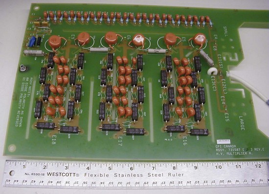
FIGURE 5-14 Rectifiers in most modern x-ray generators are the silicon, semiconductor type. The multiple black components on this 75-kVp high-voltage multiplier board are rectifiers.
It has long been known that metals are good conductors of electricity and that some other materials, such as glass and plastic, are poor conductors of electricity or insulators.
A third class of materials, called semiconductors, lies between the range of insulators and conductors in their ability to conduct electricity. Tiny crystals of these semiconductors have some useful electrical properties and allow semiconductors to serve as the basis for today’s solid-state microprocessor marvels.
Semiconductors are classed into two types: n-type and p-type. N-type semiconductors have loosely bound electrons that are relatively free to move. P-type semiconductors have spaces, called holes, where there are no electrons. These holes are similar to the space between cars in heavy traffic. Holes are as mobile as electrons.
Consider a tiny crystal of n-type material placed in contact with a p-type crystal to form what is called a p-n junction (Figure 5-15). If a higher potential is placed on the p side of the junction, then the electrons and holes will both migrate toward the junction and wander across it. This flow of electrons and holes constitutes an electric current.
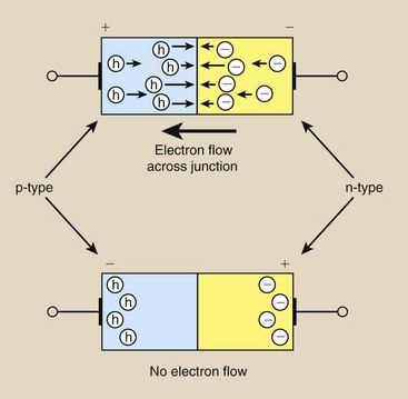
If, however, a positive potential is placed on the n side of the junction, both the electrons and the holes will be swept away from the junction, and no electrons will be available at the junction surface to form a current. Thus, in this case, no electric current passes through the p-n junction.
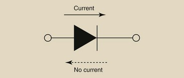
Therefore, a solid-state p-n junction tends to conduct electricity in only one direction. This type of p-n junction is called a solid-state diode. Solid-state diodes are rectifiers because they conduct electric current in only one direction. The arrowhead in the symbol for a diode indicates the direction of conventional electric current, which is opposite to the flow of electrons (Figure 5-16).
Rectification is essential for the safe and efficient operation of the x-ray tube. Rectifiers are located in the high-voltage section.
Unrectified Voltage
Figure 5-17 shows the unrectified voltage at the secondary side of the high-voltage step-up transformer. This voltage waveform appears as the voltage waveform supplied to the primary side of the high-voltage transformer except its amplitude is much greater.
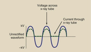
The current that passes through the x-ray tube, however, exists only during the positive half of the cycle when the anode is positive and the cathode is negative. During the negative half of the cycle, current can flow only from anode to cathode, but this does not occur because the anode is not constructed to emit electrons.
Half-Wave Rectification
The inverse voltage is removed from the supply to the x-ray tube by rectification. Half-wave rectification (Figure 5-18) is a condition in which the voltage is not allowed to swing negatively during the negative half of its cycle.
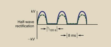
Rectifiers are assembled into electronic circuits to convert alternating current into the direct current necessary for the operation of an x-ray tube (Figure 5-19). During the positive portion of the AC waveform, the rectifier allows electric current to pass through the x-ray tube.
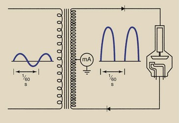
During the negative portion of the AC waveform, however, the rectifier does not conduct, and thus no electric current is allowed. The resultant electric current is a series of positive pulses separated by gaps when the negative current is not conducted.
This resultant electric current is a rectified current because electrons flow in only one direction. This form of rectification is called half-wave rectification because only one half of the AC waveform appears in the output.
In some portable and dental x-ray imaging systems, the x-ray tube serves as the vacuum tube rectifier. Such a system is said to be self-rectified, and the resulting waveform is the same as that of half-wave rectification.
Half-wave–rectified circuits contain zero, one, or two diodes. The x-ray output from a half-wave high-voltage generator pulsates, producing 60 x-ray pulses each second.
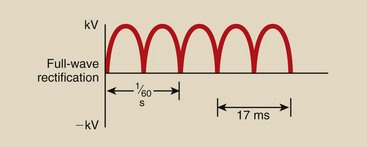
Full-Wave Rectification
One shortcoming of half-wave rectification is that it wastes half the supply of power. It also requires twice the exposure time. It is possible, however, to devise a circuit that rectifies the entire AC waveform. This form of voltage rectification is called full-wave rectification.
Full-wave–rectified x-ray imaging systems contain at least four diodes in the high-voltage circuit, usually arranged as in Figure 5-20. In a full-wave–rectified circuit, the negative half-cycle corresponding to the inverse voltage is reversed so that the anode is always positive (Figure 5-21).
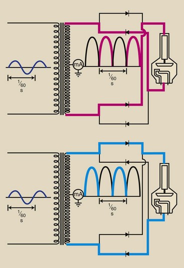
FIGURE 5-20 A full-wave–rectified circuit contains at least four diodes. Current is passed through the tube at 120 pulses per second.
The current through the circuit is shown during both the positive and the negative phases of the input waveform. Note that in both cases, the output voltage across the x-ray tube is positive. Also, there are no gaps in the output waveform. All of the input waveform is rectified into usable output.
Figure 5-22 helps explain full-wave rectification. During the positive half-cycle of the secondary voltage waveform, electrons flow from the negative side to diodes C and D. Diode C is unable to conduct electrons in that direction, but diode D can. The electrons flow through diode D and the x-ray tube.
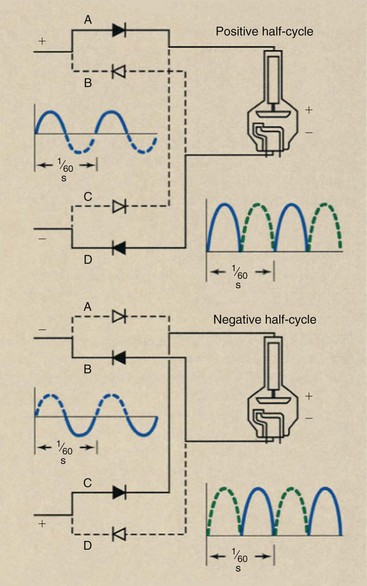
FIGURE 5-22 In a full-wave–rectified circuit, two diodes (A and D) conduct during the positive half-cycle, and two (B and C) conduct during the negative half-cycle.
The electrons then butt into diodes A and B. Only diode A is positioned to conduct them, and they flow to the positive side of the transformer, thus completing the circuit.
During the negative half-cycle, diodes B and C are pressed into service, and diodes A and D block electron flow. Note that the polarity of the x-ray tube remains unchanged. The cathode is always negative and the anode always positive even though the induced secondary voltage alternates between positive and negative.
The main advantage of full-wave rectification is that the exposure time for any given technique is cut in half. The half-wave–rectified x-ray tube emits x-rays only half of the time. The pulsed x-ray output of a full-wave–rectified machine occurs 120 times each second instead of 60 times per second as with half-wave rectification.
Single-Phase Power
All of the voltage waveforms discussed so far are produced by single-phase electric power. Single-phase power results in a pulsating x-ray beam. This is caused by the alternate swing in voltage from zero to maximum potential 120 times each second under full-wave rectification.
The x-rays produced when the single-phase voltage waveform has a value near zero are of little diagnostic value because of their low energy; such x-rays have low penetrability. One method of overcoming this deficiency is to use some sophisticated electrical engineering principles to generate three simultaneous voltage waveforms that are out of step with one another. Such a manipulation results in three-phase electric power.
Three-Phase Power
The engineering required to produce three-phase power involves the manner in which the high-voltage step-up transformer is wired into the circuit, the details of which are beyond the scope of this discussion. Figure 5-23 shows the voltage waveforms for single-phase power, three-phase power, and full-wave–rectified three-phase power.
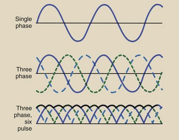
FIGURE 5-23 Three-phase power is a more efficient way to produce x-rays than is single-phase power. Shown are the voltage waveforms for unrectified single-phase power, unrectified three-phase power, and rectified three-phase power.
With three-phase power, multiple voltage waveforms are superimposed on one another, resulting in a waveform that maintains a nearly constant high voltage. There are six pulses per 1/60 s compared with the two pulses characteristic of single-phase power.
With three-phase power, the voltage applied across the x-ray tube is nearly constant, never dropping to zero during exposure.
There are limitations to the speed of starting an exposure—initiation time—and ending an exposure—extinction time. Additional electronic circuits are necessary to correct this deficiency; this adds to the additional size and cost of the three-phase generator.
High-Frequency Generator
High-frequency circuits are finding increasing application in generating high voltage for many x-ray imaging systems. Full-wave–rectified power at 60 Hz is converted to a higher frequency, from 500 to 25,000 Hz, and then is transferred to high voltage (Figure 5-24).
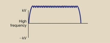
One advantage of the high-frequency generator is its size. They are very much smaller than 60-Hz high-voltage generators. High-frequency generators produce a nearly constant potential voltage waveform, improving image quality at lower patient radiation dose.
This technology was first used with portable x-ray imaging systems. Now, all mammography and computed tomography systems use high-frequency circuits.
High-frequency voltage generation uses inverter circuits (Figure 5-25). Inverter circuits are high-speed switches, or choppers, that convert DC into a series of square pulses.
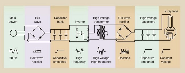
Many portable x-ray high-voltage generators use storage batteries and silicon-controlled rectifiers (SCRs) to generate square waves at 500 Hz; this becomes the input to the high-voltage step-up transformer. The high-voltage step-up transformer operating at 500 Hz is about the size of a 60-Hz transformer, which is rather large and heavy.
High-frequency x-ray generators are sometimes grouped by frequency (Table 5-1). The principal differences are found in the electric components designed as the inverter module. The real advantage of such circuits is that they are much smaller, less costly, and more efficient than 60-Hz high-voltage generators.
Capacitor Discharge Generator
Some portable x-ray imaging systems still use a high-voltage generator, which operates by charging a series of SCRs from the DC voltage of a nickel–cadmium (NiCd) battery. By stacking (in an electric sense) the SCRs, the charge is stored at very high voltage. During exposure, the charge is released (discharged) to form the x-ray tube current needed to produce x-rays (Figure 5-26).
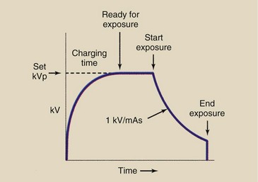
This falling voltage limits the available x-ray tube current and causes kVp to fall during exposure. The result is the need for precise radiographic technique charts.
After a given exposure time, the capacitor bank continues to discharge, which could cause continued x-ray emission. Such x-ray emission is stopped by a grid-controlled x-ray tube, an automatic lead beam stopper, or both. A grid-controlled x-ray tube has a specially designed cathode to control x-ray tube current.
Falling Load Generator
Many x-ray imaging systems today engage a falling load technique to ensure the shortest possible exposure time. The x-ray tube anode can accommodate only a limited heat level as we shall see in Chapter 6.
Supposing the limit on exposure time, and therefore x-ray intensity, for an interventional radiology imaging system at the 1000 mA station is 500 ms and therefore 500 mAs as shown in Figure 5-27. At the selected kVp and 1000 mA, the shortest exposure time allowed is 500 ms because of the thermal capacity of the x-ray tube anode.
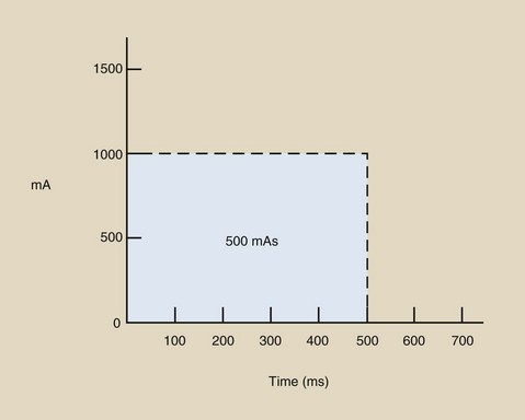
FIGURE 5-27
When an x-ray tube anode is heated, it immediately begins to cool. The approach of falling load voltage generation is that the initial tube loading is higher and drops during exposure as shown in Figure 5-28. The rate of drop follows the cooling characteristics of the x-ray tube anode. The result is the same 500 mAs at shorter exposure time, 300 ms in this example.
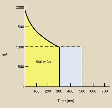
FIGURE 5-28
Falling load voltage generation finds principal use in high-capacity x-ray imaging systems such as interventional radiology in which the shorter the exposure time the better.
Voltage Ripple
Another way to characterize these voltage waveforms is by voltage ripple. Single-phase power has 100% voltage ripple: The voltage varies from zero to its maximum value. Three-phase, six-pulse power produces voltage with only approximately 14% ripple; consequently, the voltage supplied to the x-ray tube never falls to below 86% of the maximum value.
A further improvement in three-phase power results in 12 pulses per cycle rather than 6. Three-phase, 12-pulse power results in only 4% ripple; therefore, the voltage supplied to the x-ray tube does not fall to below 96% of the maximum value. High-frequency generators have approximately 1% ripple and therefore greater x-ray quantity and quality.
Figure 5-29 shows these various power sources and the resultant voltage waveforms they provide to the x-ray tube, as well as the approximate voltage ripple. The most efficient method of x-ray production also involves the waveform with the lowest voltage ripple.
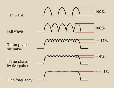
FIGURE 5-29 Voltage waveforms resulting from various power supplies. The ripple of the kilovoltage is indicated as a percentage for each waveform.
An x-ray tube voltage with less ripple offers many advantages. The principal advantage is the greater radiation quantity and quality that result from the more constant voltage supplied to the x-ray tube (Figure 5-30).
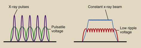
FIGURE 5-30 Both the number of x-rays and the x-ray energy increase as the voltage waveform increases.
The radiation quantity is greater because the efficiency of x-ray production is higher when x-ray tube voltage is high. Stated differently, for any projectile electron emitted by the x-ray tube filament, a greater number of x-rays are produced when the electron energy is high than when it is low.
Low-voltage ripple increases radiation quality because fewer low-energy projectile electrons pass from cathode to anode to produce low-energy x-rays. Consequently, the average x-ray energy is greater than that resulting from high-voltage ripple modes.
Because the x-ray beam intensity and penetrability are greater for less voltage ripple than for single-phase power, technique charts developed for one cannot be used on the other. New technique charts with three-phase or high-frequency x-ray imaging systems are needed.
Three-phase operation may require as much as a 10-kVp reduction to produce the same image receptor exposure when operated at the same mAs as single phase. A high-frequency generator may require a 12-kVp reduction.
Three-phase radiographic equipment is manufactured with tube currents as high as 1200 mA; therefore, exceedingly short, high-intensity exposures are possible. This capacity is particularly helpful in interventional radiology procedures.
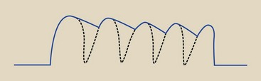
When three-phase power is provided for a radiographic/fluoroscopic room, all radiographic exposures are performed with three-phase power. The fluoroscopic mode, however, usually remains single-phase and takes advantage of the electric capacitance of the x-ray tube cables.
Fluoroscopic mA is very low compared with radiographic mA. Because the x-ray cables are long, they have considerable capacitance, which results in a smoother voltage waveform (Figure 5-31).
The principal disadvantage of a three-phase x-ray apparatus is its initial cost. The costs of installation and operation, however, can be lower than those associated with single-phase equipment. The cost of high-frequency generators is moderate. Low-ripple generators have greater overall capacity and flexibility compared with single-phase equipment.
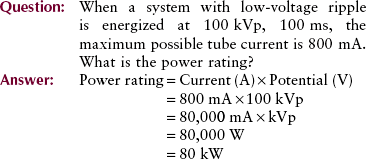
Power Rating
Transformers and high-voltage generators usually are identified by their power rating in kilowatts (kW). Electric power for any device is specified in watts, as shown in the following equation.

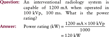
A high-voltage generator for a basic radiographic unit is rated at 30 to 50 kW. Generators for interventional radiology suites have power ratings up to approximately 150 kW.
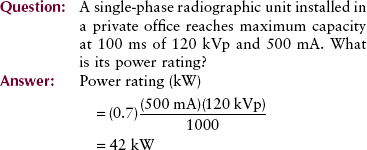
For specifying high-voltage generators, the industry standard is to use the maximum tube current (mA) possible at 100 kVp for an exposure of 100 ms. This generally results in the maximum available power.
Power is the product of amperes and volts. This assumes constant current and voltage, which does not exist in single-phase x-ray imaging systems. However, the actual power is close enough to the low-ripple power of three-phase and high-frequency generators that the equation holds.
Because the product of amperes × volts = watts, the product of milliamperes × kilovolts = watts. However, power rating is expressed in kilowatts, so the defining equation for three-phase and high-frequency power is as follows:
Single-phase generators have 100% voltage ripple and are less efficient x-ray generators. Consequently, the single-phase expression of power rating is as follows:
X-ray Circuit
Figure 5-32 is a simplified schematic diagram of the three main sections of the x-ray imaging system: the x-ray tube, the operating console, and the high-voltage generator. This figure also shows the locations of all meters, controls, and important components.
Summary
The x-ray imaging system has three principal sections: (1) the x-ray tube, (2) the operating console, and (3) the high-voltage generator. The design and operation of the x-ray tube are discussed in Chapter 6.
The operating console consists of an on/off control and controls to select kVp, mA, and time or mAs. The AECs are also located on the operating console.
The high-voltage generator provides power to the x-ray tube in three possible ways: single-phase power, three-phase power, and high-frequency power. The difference between single- and three-phase power involves the manner in which the high-voltage step-up transformer is electrically positioned. With three-phase power, the voltage across the x-ray tube is nearly constant during exposure and never drops to zero, as does the voltage for single-phase power.
The components of an x-ray imaging system are sometimes identified by their power rating in kilowatts (kW). Maximum available power for high-voltage generators equals the maximum tube current (mA) at 100 kVp for an exposure of 100 ms.
1. Define or otherwise identify the following:
2. 220 V is supplied across 1200 windings of the primary coil of the autotransformer. If 1650 windings are tapped, what voltage will be supplied to the primary coil of the high-voltage transformer?
3. A kVp meter reads 86 kVp, and the turns ratio of the high-voltage step-up transformer is 1200. What is the true voltage across the meter?
4. The supply voltage from the autotransformer to the filament transformer is 60 V. If the turns ratio of the filament transformer is  , what is the filament voltage?
5. If the current in the primary of the filament transformer in question 4 were 0.5 A, what would be the filament current?
6. The supply to a high-voltage step-up transformer with a turns ratio of 550 is 190 V. What is the voltage across the x-ray tube?
7. Locate the various meters and controls shown in Figure 5-32 on an x-ray imaging system you operate.
8. The radiographic table must be radiolucent. Define radiolucent.
9. Describe the movements of a patient couch.
10. List the five major controls on the operator’s console.
11. What is the purpose of the autotransformer?
12. How does primary voltage relate to secondary voltage in an autotransformer?
13. What does the prereading kVp meter allow?
14. Operating console controls are set at 200 mA with an exposure time of s. What is the milliampere-seconds (mAs)?
15. In an examination of a pediatric patient, the operating console controls are set at 600 mA/30 ms. What is the mAs?
16. What is the difference between a high-voltage generator and a high-voltage transformer?
17. Why does the x-ray circuit require rectification?
18. Match the power source with the voltage ripple.
| Power | % Voltage Ripple |
| Single phase | 14% |
| Three phase, six pulse | 100% |
| Three phase, twelve pulse | 14% |
| High frequency | 1% |
19. What is the only type of high-voltage generator that can be positioned in or on the x-ray tube housing?
20. State the equations for computing single-phase and high-frequency power rating.
The answers to the Challenge Questions can be found by logging on to our website at http://evolve.elsevier.com.