Digital Fluoroscopy
At the completion of this chapter, the student should be able to do the following:
1 Describe the parts of a digital fluoroscopy imaging system and explain their functions.
2 Compute pixel size in digital fluoroscopy.
3 Describe the properties and use of a charge-coupled device instead of a TV camera tube.
4 Understand the advantages to using a flat panel image receptor.
5 Outline the procedures for temporal subtraction and energy subtraction.
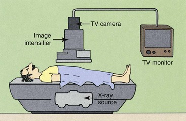
CONVENTIONAL FLUOROSCOPY produces a shadowgraph-type image on a receptor that is directly produced from the transmitted x-ray beam. Image-intensifier tubes serve as the fluoroscopic image receptor. These tubes usually are coupled electronically to a television monitor for remote viewing, as described in Chapter 25. Figure 26-1 diagrams the components used in conventional fluoroscopy.
Digital fluoroscopy (DF) is a digital x-ray imaging system that produces dynamic images obtained with an area x-ray beam. The difference between conventional fluoroscopy and DF is the nature of the image and the manner in which it is digitized.
The medical physics groups at the University of Wisconsin and the University of Arizona independently initiated studies of DF in the early 1970s. These studies have been continued by the research and development groups of most x-ray imaging system manufacturers.
The early approach was to use fluoroscopic equipment while placing a computer between the television camera tube and the television monitor. The video signal from the television camera tube was routed through the computer, manipulated in various ways, and transmitted to a television monitor in a form ready for viewing.
 Advantages of DF over conventional fluoroscopy include the speed of image acquisition and postprocessing to enhance image contrast.
The initial investigators of DF demonstrated that nearly instantaneous, high-contrast subtraction images could be obtained after intravenous (IV) injection of contrast media. Although the IV route is still widely used, intraarterial injections are also used with DF.
A 1024 × 1024 image matrix sometimes is described as a 1000-line system. In DF, the spatial resolution is determined both by the image matrix and by the size of the image intensifier. Spatial resolution is limited by pixel size.
 DF Pixel Size
| Question: | What is the pixel size of a 1000-line DF system operating in the 12 cm mode? |
| Answer: | Twelve cm equals 120 mm; therefore, the size of each pixel is 120 mm/1024 pixels = 0.117 mm/pixel or 117 µm/pixel |
Digital Fluoroscopy Imaging System
A DF examination is conducted in much the same manner as a conventional fluoroscopic study. To the casual observer, the equipment is the same, but such is not the case (Figure 26-2). A computer has been added, as have multiple monitors and a more complex operating console (Figure 26-3).
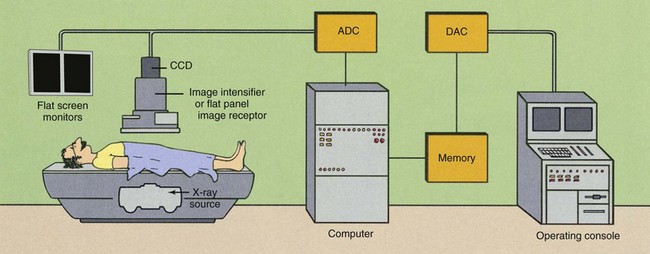
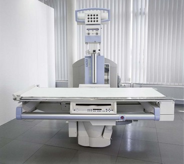
FIGURE 26-3 An installed remotely controlled digital fluoroscopic system with an over-table tube and under-table image receptor. (Courtesy Siemens Medical Solutions USA.)
Figure 26-4 shows a representative operating console of a dedicated DF imaging system. It contains alphanumeric and special function keys in the right module for entering patient data and communicating with the computer. The right portion of the console contains additional special function keys for data acquisition and image display.

FIGURE 26-4 Operating console for a digital fluoroscopy system. (Courtesy Siemens Medical Solutions USA.)
The module on the right also contains computer-interactive video controls and a pad for cursor and region-of-interest manipulation. Other systems use a trackball, a joystick, or a mouse instead of the pad. At least two monitors are used. Here in Figure 26-4 the right monitors are used to edit patient and examination data and to annotate final images. The left monitors display subtracted images.
During DF, the under-table x-ray tube actually operates in the radiographic mode. Tube current is measured in hundreds of mA instead of less than 5 mA, as in image-intensifying fluoroscopy.
This is not a problem, however. If the tube were energized continuously, it would fail because of thermal overloading, and the patient radiation dose would be exceedingly high. Images from DF are obtained by pulsing the x-ray beam in a manner called pulse-progressive fluoroscopy, as is shown in Figure 26-5.
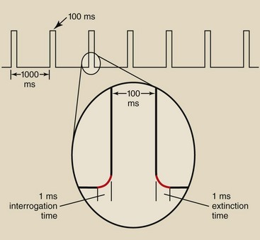
FIGURE 26-5 Pulse-progressive fluoroscopy involves terms such as duty cycle, interrogation time, and extinction time.
Image acquisition rates of 1 per second to 10 per second are common in many examinations. Because 33 ms is required to produce a single video frame, x-ray exposures longer than this can result in unnecessary patient radiation doses. This is a theoretical limit, however, and longer exposures may be necessary to ensure low noise and good image quality.
If a flat panel is the fluoroscopic image receptor instead of an II tube, x-ray exposure time can be continuously varied for even greater patient radiation dose reduction. Each time the flat panel is exposed, it is read immediately and the image projected until the next image is acquired.
Consequently, the x-ray generator must be capable of switching on and off very rapidly. The time required for the x-ray tube to be switched on and reach selected levels of kilovolt peak (kVp) and mA is called the interrogation time. The time required for the x-ray tube to be switched off is the extinction time (Figure 26-5). DF systems must incorporate high-frequency generators with interrogation and extinction times of less than 1 ms.
The fraction of time that the x-ray tube is energized is called the duty cycle. Figure 26-5 also shows that the x-ray tube is energized for 100 ms every second. This represents a 10% duty cycle. This feature of pulse-progressive DF can result in significant patient radiation dose reduction.
Pulse progressive fluoroscopy is essential for reducing patient radiation dose and should be routinely used. The Alliance for Radiation Safety in Adult Patient Imaging—Image wisely endorses “pause and pulse” during pediatric fluoroscopy. This means carefully planning and preparing before starting fluoroscopy and pulsing the fluoroscopic x-ray beam at the lowest frame rate. This approach has also been adopted by the “Image Gently” campaign for pediatric imaging.
Image Receptor
A major change from conventional fluoroscopy to DF is the use of a charge-coupled device (CCD) instead of a TV camera tube, as is shown in Figure 26-2. The CCD was developed in the 1970s for military applications, especially in night vision scopes. Today, CCDs are used in the digital camera, commercial television, security surveillance, and astronomy (Figure 26-6).
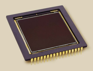
FIGURE 26-6 This charge-coupled device consists of 14-µm pixels arrayed in a 2048 × 2048 matrix; it views the light output of an image-intensifier tube. (Courtesy Apogee Instruments Inc.)
The demands of medical imaging are much more rigorous than in these other applications. That is why the application of the CCD in fluoroscopy is a recent development.
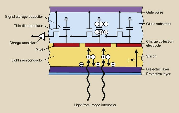
The sensitive component of a CCD is a layer of crystalline silicon (Figure 26-7). When this silicon is illuminated, electrical charge is generated, which is then sampled, pixel by pixel, and manipulated to produce a digital image.
The CCD is mounted on the output phosphor of the image-intensifier tube and is coupled through fiberoptics (Figure 26-8) or a lens system (Figure 26-9). In fact, such coupling is far more complex than that shown in Figure 26-9.
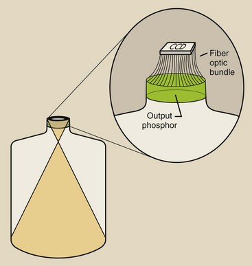
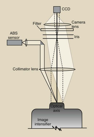
FIGURE 26-9 An example of a lens-coupling system for a charge-coupled device (CCD) to an image intensifier.
Note the device in Figure 26-9 that is labeled “ABS sensor.” With a lens-coupled CCD, a sample of light is measured and is used to drive the automatic brightness stabilization (ABS) system.
When the CCD is directly coupled to the image intensifier, the entire CCD signal is sampled and drives the ABS system.
The principal advantage of CCDs in most applications, such as a digital camera, is their small size and ruggedness. The principal advantages of their use for medical imaging are listed in Box 26-1.
The spatial resolution of a CCD is determined by its physical size and pixel count. Systems that incorporate a 1024 matrix can produce images with 10 lp/mm spatial resolution. Television camera tubes can show spatial distortion in what is described as “pin cushion” or “barrel” artifact. No such distortion occurs with a CCD.
The CCD has greater sensitivity to light (detective quantum efficiency) and a lower level of electronic noise than a television camera tube. The results are a higher signal-to-noise ratio (SNR) and better contrast resolution. These characteristics also result in substantially lower patient radiation doses.
The response of the CCD to light is very stable. Warm-up of the CCD is not required. Neither image lag nor blooming is present. It has essentially an unlimited lifetime and requires no maintenance.
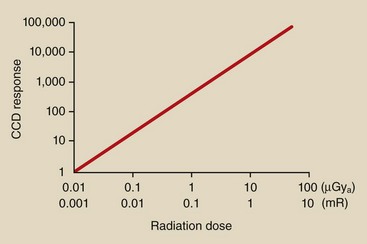
Perhaps the single most important feature of CCD imaging is its linear response (Figure 26-10). The linear response feature is particularly helpful for digital subtraction angiography (DSA) and results in improved dynamic range and better contrast resolution.
Flat Panel Image Receptor
The further improvement of DF imaging is developing the flat panel image receptor (FPIR). Such an image receptor is composed of cesium iodide (CsI)/amorphous silicon (a-Si) pixels, as described in Chapter 16 for digital radiography.
An installed FPIR fluoroscopic system is shown in Figure 26-11. Several features are immediately obvious. The FPIR is much smaller and lighter and is manipulated more easily than an image intensifier. The FPIR imaging suite provides easier patient manipulation and radiologist or technologist movement, and there are no radiographic cassettes.
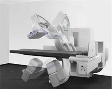
FIGURE 26-11 A digital fluoroscope equipped with a flat panel image receptor. (Courtesy Siemens Medical Solutions USA.)
However, ease of use is not the principal reason why FPIR will prevail as the digital fluoroscope of choice. Box 26-2 lists some advantages of FPIR over image-intensified fluoroscopy.
The image intensifier is limited by nonuniform spatial resolution and contrast resolution from the center to the periphery of the circular image. Veiling glare and pincushion distortion increase with age on an image intensifier. The response of an FPIR is uniform over the entire receptor and does not degrade with age.
The image captured by an FPIR is square or rectangular, similar to the associated flat panel monitors (see Chapter 18).
In contrast to an image-intensifier tube, the FPIR is insensitive to external magnetic fields. This has made possible a new area of interventional radiography: image-guided catheter navigation (Figure 26-12).
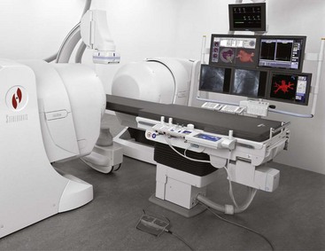
FIGURE 26-12 Flat panel image receptor (FPIR) fluoroscopy makes magnetic steering possible. (Courtesy Siemens Medical Solutions USA.)
A special catheter with a magnetic tip is introduced into the patient vasculature. This catheter is manipulated remotely through tortuous vessels by two large steering magnets that are located on either side of the patient. This technology will find advanced application in cardiology and in neurovascular radiology.
Image Display
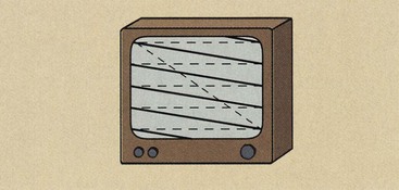
The video system used in conventional fluoroscopy is usually a 525-line system. Such a system is inadequate for DF.
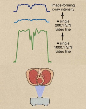
Conventional video has two limitations that restrict its application in digital techniques. First, the interlaced mode of reading the target of the television camera tube can significantly degrade a digital image. Second, conventional television camera tubes are relatively noisy. They have an SNR of about 200 : 1; an SNR of 1000 : 1 is necessary for DF.
Interlaced Versus Progressive Mode
In Chapter 25, the method by which a conventional television camera tube reads its target assembly is described. This method was called an interlaced mode, wherein two fields of  lines were read individually in 1/60 s (17 ms) to form a 525-line video frame in 1/30 s (33 ms).
In DF, the TV camera tube reads in progressive mode. When the video signal is read in the progressive mode, the electron beam of the TV camera tube sweeps the target assembly continuously from top to bottom in 33 ms (Figure 26-13).
The video image is formed similarly on the television monitor. No interlace of one field with another occurs. This produces a sharper image with less flicker.
Signal-to-Noise Ratio
All analog electronic devices are inherently noisy. Because of heated filaments and voltage differences, a very small electric current always is flowing in any circuit. This is called background electronic noise. It is similar to the noise (fog) on a radiograph in that it conveys no information and serves only to obscure the electronic signal and reduce image contrast.
Because conventional television camera tubes have an SNR of about 200 : 1, the maximum output signal will be 200 times greater than the background electronic noise. An SNR of 5 : 1 is minimally visible.
An SNR of 200 : 1 is not sufficient for DF because the video signal is rarely at maximum, and lower signals become even more lost in the noise. This is especially true when subtraction techniques are used. Image contrast resolution is severely degraded by a system with a low SNR.
Figure 26-14 illustrates the difference between the output of a 200 : 1 SNR television camera tube and that of a 1000 : 1 tube. At 200 : 1, the dynamic range is less than 28, and at 1000 : 1, it is approximately 210. The tube with a 1000 : 1 SNR provides five times the useful information and is more compatible with computer-assisted image enhancement.
Flat Panel Image Display
Flat panel display technology is rapidly replacing the cathode ray tube (CRT) in all applications. Flat panel displays for television become ever more popular as the price of such devices shrinks.
The flat panel display is similarly and rapidly replacing CRTs in radiography and fluoroscopy as well. This advance in image monitoring is discussed in greater detail in Chapter 18.
It is presently known that the use of flat panel display technology in fluoroscopy has many advantages over the use of CRTs. They are light in weight, easy to see, and can be readily mounted suspended in an angiographic room.
Digital Subtraction Angiography
Minicomputers and microprocessors are used in DF. The capacity of the computer is an important factor in determining image quality, the manner and speed of image acquisition, and the means of image processing and manipulation. Important characteristics of a DF system that are computer controlled include the image matrix size, the system dynamic range, and the image acquisition rate.
The output signal from the image-intensified digital image receptor is transmitted to an analog-to-digital converter (ADC). The ADC accepts the continuously varying signal—the analog signal—and digitizes it. The signal from an FPIR is already digital.
To be compatible with the computer, the ADC must have the same dynamic range as the DF system. An 8-bit ADC would convert the analog signal into values between 0 and 255. A 10-bit ADC would be more precise, with an ADC range from 0 to 210 or 0 to 1023. The output of the ADC is then transferred to main memory and is manipulated so that a digital image in matrix form is stored.
The dynamic range of each pixel, the number of pixels, and the method of storage determine the speed with which the image can be acquired, processed, and transferred to an output device.
If image storage occurs in primary memory, which is usually the case, then data acquisition and transfer can be as rapid as 30 images per second. In general, if the image matrix is doubled (e.g., from 512 to 1024), the image acquisition time will be increased by four.
A representative system might be capable of acquiring 30 images per second in the 512 × 512 matrix mode. However, if a higher spatial resolution image is required and the 1024 × 1024 mode is requested, then only 8 images per second can be acquired. This limitation on data transfer is imposed by the time required to transport enormous quantities of data from one segment of memory to another.
Image Formation
The principal advantages of DF examinations are the image subtraction techniques that are possible and the enhanced visualization of vasculature that results from venous injection of contrast material. Unfortunately, an area beam must be used, which reduces image contrast because of associated Compton scatter radiation.
Image contrast, however, can be enhanced electronically. Image contrast is improved by subtraction techniques that provide instantaneous viewing of the subtracted image during passage of a bolus of contrast medium.
Temporal subtraction and energy subtraction are the two methods that receive attention in DF. Each has distinct advantages and disadvantages, and these are described in Table 26-1. Temporal subtraction techniques are used most frequently because of high-voltage generator limitations associated with the energy subtraction mode. When the two techniques are combined, the process is called hybrid subtraction. Image contrast is enhanced still further by hybrid subtraction because of reduced patient motion between subtracted images.
Table 26-1
Comparison of Temporal and Energy Subtraction
| Temporal Subtraction | Energy Subtraction |
| A single kVp setting is used. | Rapid kVp switching is required. |
| Normal x-ray beam filtration is adequate. | X-ray beam filter switching is preferred. |
| Contrast resolution of 1 mm at 1% is achieved. | Higher x-ray intensity is required for comparable contrast resolution. |
| Simple arithmetic image subtraction is necessary. | Complex image subtraction is necessary. |
| Motion artifacts are a problem. | Motion artifacts are greatly reduced. |
| Total subtraction of common structures is achieved. | Some residual bone may survive subtraction. |
| Subtraction possibilities are limited by the number of images. | Many more types of subtraction images are possible. |
Temporal Subtraction
Temporal subtraction refers to a number of computer-assisted techniques whereby an image obtained at one time is subtracted from an image obtained at a later time. If, during the intervening period, contrast material was introduced into the vasculature, the subtracted image will contain only the vessels filled with contrast material. Two methods are commonly used: the mask mode and the time-interval difference (TID) mode.
Mask Mode
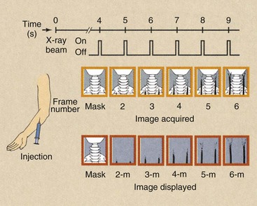
A typical mask-mode procedure is diagrammed in Figure 26-15. The patient is positioned under normal fluoroscopic control to ensure that the region of anatomy under investigation is within the field of view.
A power injector is armed and readied to deliver 30 to 50 mL of contrast material at the rate of approximately 15 to 20 ml/s through a venous entry. If an arterial entry is chosen, 10 to 25 ml of diluted contrast material at 10 to 12 ml/s is typical.
The imaging system is changed from the fluoroscopic mode to the DF mode. This requires an increase in x-ray tube current of 20 to 100 times the fluoroscopic mode and the activation of a program of pulse image acquisition.
The injector is fired, and after a delay of 4 to 10 s, before the bolus of contrast medium reaches the anatomic site, an initial x-ray pulsed exposure is made. The image obtained is stored in primary memory and is displayed on video monitor A. This is the mask image.
This mask image is followed by a series of additional images that are stored in adjacent memory locations. While these subsequent images are being acquired, the mask image is subtracted from each and the result stored in primary memory. At the same time, the subtracted image is displayed on video monitor B.
Figure 26-16, A, shows a preinjection mask lateral view of the base of the skull, an image following contrast injection (Figure 26-16, B), and a DSA image obtained by subtracting the mask from the injection image (Figure 26-16, C). The principal result of DSA is improved image contrast.
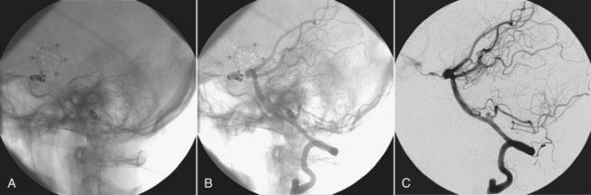
FIGURE 26-16 A, The preinjection mask. B, A postinjection image. C, Image produced when the preinjection mask is subtracted from the postinjection image. (Courtesy Charles Trihn, Baylor College of Medicine.)
Digital subtraction of the static object (the skull) allows better analysis of the opacified arteries, especially in their distal parts.
The subtracted images appear in real time and are then stored in memory. After the examination, each subtracted image can be recalled for closer examination.
As is described here, each image was obtained from a 33-ms x-ray pulse. The time required for one video frame is 33 ms. Because the video system is relatively slow to respond and the video noise may be high, several video frames (usually four or eight) may be summed in memory to create each image. This process is called image integration. Although the process improves contrast resolution, it also increases the patient dose because a greater number of image frames are acquired.
In mask-mode DF, the imaging sequence after acquisition of the mask can be controlled manually or preprogrammed. If preprogrammed, the computer controls data acquisition in accordance with the demands of the examination.
To evaluate carotid flow, for example, after a brachial vein injection, the radiologist could inject contrast media and acquire a mask image 2 s after the injection. After another 2-s delay, images are obtained at the rate of two per second for 3 s, one per second for 5 s, and one every other second for 14 s. If the computer capacity for acquiring images is sufficient, any combination of multiple delays and varying image acquisition rates is possible.
Remasking
If, on subsequent examination, the initial mask image is inadequate because of patient motion or improper technique or for any other reason, later images may be used as the mask image. A typical examination may require a total of 30 images in addition to the mask image.
If the intended mask image is technically inadequate and maximum contrast appears during the 15th image, a better subtraction image may be obtained by using image number 5 as the mask rather than image number 1. The examiner can even integrate several images (e.g., numbers four through eight) using the composite image as the mask. Unacceptable mask images can be caused by noise, motion, and technical factors.
Time-Interval Difference Mode
Some examinations call for each subtracted image to be made from a different mask and follow-up frame (Figure 26-17). In a cardiac study, for example, image acquisition begins 5 s after injection at the rate of 15 images per second for 4 s. A total of 60 images is obtained in such a study. These images are identified as frame numbers 1 through 60. Each image is stored in a separate memory address as it is acquired.
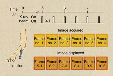
FIGURE 26-17 The manner in which sequentially obtained images is subtracted in a time-interval difference study.
If a TID of four images (268 ms) is selected, the first image to appear will be that obtained when frame one is subtracted from frame five. The second image will contain the subtraction of frame two from frame six; the third will contain the subtraction of frame three from frame seven and so forth.
In real time, the images observed convey the flow of contrast medium dynamically. Subsequent closer examination of each TID image shows it to be relatively free of motion artifacts but with less contrast than mask-mode imaging. As a result, TID imaging is applied principally in cardiac evaluation.
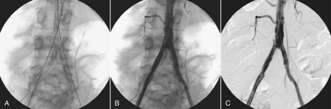
Figure 26-18 shows a typical digital subtraction angiogram of the abdominal aorta. First, a mask image (A) is obtained, then a postinjection image (B), and finally a subtracted image (C).
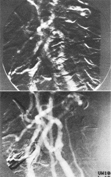
Misregistration
If patient motion occurs between the mask image and a subsequent image, the subtracted image will contain misregistration artifacts (Figure 26-19). The same anatomy is not registered in the same pixel of the image matrix. This type of artifact frequently can be eliminated by reregistration of the mask, that is, by shifting the mask by one or more pixels so that superimposition of images is again obtained.
Energy Subtraction
Temporal subtraction techniques take advantage of changing contrast media during the time of the examination and require no special demands on the high-voltage generator. Energy subtraction uses two different x-ray beams alternately to provide a subtraction image that results from differences in photoelectric interaction.
The basis for this technique is similar to that described in Chapter 12 for rare Earth screens. It is based on the abrupt change in photoelectric absorption at the K edge of contrast media compared with that for soft tissue and bone.
Figure 26-20 shows the probability of x-ray interaction with iodine, bone, and muscle as a function of x-ray energy. The probability of photoelectric absorption in all three decreases with increasing x-ray energy. At an energy of 33 keV, an abrupt increase in absorption is noted in iodine and a modest decrease in soft tissue and bone.
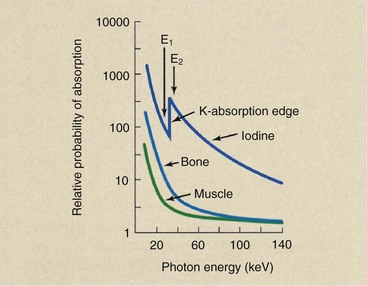
This energy corresponds to the binding energy of the two K-shell electrons of iodine. When the incident x-ray energy is sufficient to overcome the K-shell electron binding energy of iodine, an abrupt and large increase in absorption occurs.
If monoenergetic x-ray beams of 32 and 34 keV could be used alternately, the difference in absorption of iodine would be enormous, and resultant subtraction images would have very high contrast. Such is not the case, however, because every x-ray beam contains a wide spectrum of energies.
Energy subtraction has the decided disadvantage of requiring some method of providing an alternating x-ray beam of two different emission spectra. Two methods have been devised, 1) alternately pulsing the x-ray beam at 70 kVp and then 90 kVp and (2) introducing dissimilar metal filters into the x-ray beam alternately on a flywheel.
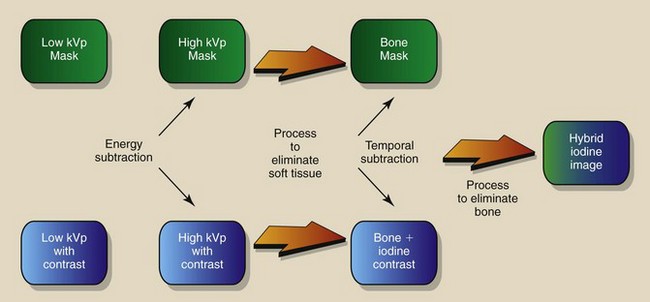
Hybrid Subtraction
Some DF systems are capable of combining temporal and energy subtraction techniques into what is called hybrid subtraction (Figure 26-21). Image acquisition follows the mask-mode procedure, as was described previously. Here, however, the mask and each subsequent image are formed by an energy subtraction technique. If patient motion can be controlled, hybrid imaging theoretically can produce the highest-quality DF images.
Roadmapping
Roadmapping is a special application of DSA. A mask image is acquired and stored. The contrast material is injected and subtraction images are acquired as in DSA, as shown in Figure 26-22, A. However, additional steps follow.
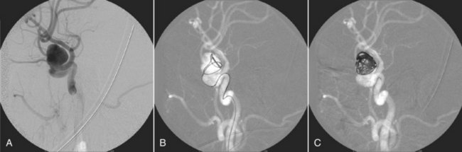
FIGURE 26-22 A roadmapping neurovascular image. (Courtesy Michael Mawad, Baylor College of Medicine.)
As the catheter is fluoroscopically advanced, the image is formed by subtraction from the second mask. The result is shown in Figure 26-22, B—a black guidewire or catheter in a white vessel.
The final DSA image shows the complete vascular tree with good contrast. This last image is inverted and is used as the mask for additional DSA images.
Patient Radiation Dose
One potential advantage of DF is reduced patient dose. DF images appear to be continuous, but in fact, they are discrete. Most DF x-ray beams are pulsed to fill one or more 33-ms video frames; therefore, the fluoroscopic dose rate is lower than that for continuous analog fluoroscopy even though the mA setting may be higher.
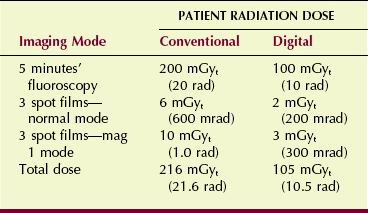
Static images with DF also are made with a lower patient radiation dose per frame than those attained with a 100-mm spot-film camera. Both the television camera tube and the CCD have greater sensitivity than the spot film. Table 26-2 compares a representative fluoroscopic study performed conventionally versus one performed digitally.
Digital spot images are so easy to acquire that it is possible to make more exposures than are necessary. If the fluoroscopist gets carried away, patient radiation dose savings will disappear.
Summary
Digital fluoroscopy has added a computer, at least two monitors, and a complex control panel to conventional fluoroscopy equipment. The minicomputers in DF control the image matrix size, the system dynamic range, and the image acquisition rate. Eight to 30 images per second can be acquired with DF, depending on the image matrix mode.
Subtraction is the process of removing or masking all unnecessary anatomy from an image and enhancing only the anatomy of interest. With DF, subtraction is accomplished by temporal or energy subtraction.
Digital image processing can be used in diagnostic imaging departments for the picture archiving and communication system. The file room can be replaced by a magnetic or optical memory device about the size of a desk. Teleradiology is the remote transmission of digital images to workstations in other areas of the hospital or offsite.
1. Define or otherwise identify the following:
2. What are the principal advantages of DF over conventional fluoroscopy?
3. Describe the sequence of image acquisition in mask-mode fluoroscopy.
4. Describe the differences between a video system operating in the interlace mode and one operating in the progressive mode.
5. Why are all electronic devices inherently noisy?
6. Describe the process of energy subtraction.
7. What determines the spatial resolution of a DF system?
8. A DF system is operated in a 512 × 512 image mode with a 23-cm image intensifier. What is the size of each pixel?
9. The dynamic range of some DF systems is described as 12 bits deep. What does this mean?
10. What principally determines spatial resolution in digital fluoroscopy?
11. How is automatic brightness stabilization implemented with FPIR fluoroscopy?
12. What is the pixel size of a 1000-line video system when the DF image intensifier is operated in the 12-cm mode?
13. How does a fluoroscopic image captured by FPIR differ from that captured with an II-CCD?
14. What additional equipment is required to progress from conventional fluoroscopy to DF?
15. Discuss the patient dose implications associated with DF compared with conventional fluoroscopy.
16. What is image-guided catheter navigation?
17. What x-ray energy (keV) would result in greatest contrast in digital subtraction angiography when an iodinated contrast agent is used (Eb = 33 keV)?
18. What are some advantages associated with the use of a CCD instead of a TV camera tube?
The answers to the Challenge Questions can be found by logging on to our website at http://evolve.elsevier.com.