Designing for Radiation Protection
At the completion of this chapter, the student should be able to do the following:
1 Name the leakage radiation limit for x-ray tubes
2 List nine radiation protection features of a radiographic imaging system
3 List nine radiation protection features of a fluoroscopic imaging system
4 Discuss the design of primary and secondary radiation barriers
5 Describe the three types of radiation dosimeters used in diagnostic imaging
A NUMBER of features of modern x-ray imaging systems designed to improve radiographic quality have been discussed in previous chapters. Many of these features are also designed to reduce patient radiation dose during x-ray examinations. For instance, proper beam collimation contributes to improved image contrast and is effective in reducing patient radiation dose.
More than 100 individual radiation protection devices and accessories are associated with modern x-ray imaging systems. Some are characteristic of either radiographic or fluoroscopic imaging systems, and some are mandated by federal regulation for all diagnostic x-ray imaging systems. A description of the devices required for all diagnostic x-ray imaging systems follows.
Radiographic Protection Features
Many radiation protection devices and accessories are associated with modern x-ray imaging systems. Two that are appropriate for all diagnostic x-ray imaging systems relate to the protective housing of the x-ray tube and to the control panel.
Protective X-ray Tube Housing
Every x-ray tube must be contained within protective housing that reduces leakage radiation during use.
Control Panel
The control panel must indicate the conditions of exposure and must positively indicate when the x-ray tube is energized. These requirements are usually satisfied with the use of kVp and mA indicators. Sometimes, visible or audible signals indicate when the x-ray beam is energized.
Source-to-Image Receptor Distance Indicator
A source-to-image receptor distance (SID) indicator must be provided. This can be as simple as a tape measure attached to the tube housing, or as advanced as lasers.
Collimation
Light-localized, variable-aperture rectangular collimators should be provided. Cones and diaphragms may replace the collimator for special examinations. Attenuation of the useful beam by collimator shutters must be equivalent to attenuation by the protective housing.
| Question: | Most radiographs are taken at an SID of 100 cm. How much difference is allowed between the projection of the light field and the x-ray beam at the image receptor? |
| Answer: | 2% of 100 cm = 2 cm |
Positive-Beam Limitation
Automatic, light-localized, variable-aperture collimators were required on all but special x-ray imaging systems manufactured in the United States between 1974 and 1994. These positive-beam–limiting (PBL) devices are no longer required but continue to be a part of most new radiographic imaging systems. They must be adjusted so that with any image receptor size in use and at all standard SIDs, the collimator shutters automatically provide an x-ray beam equal to the image receptor.
Beam Alignment
In addition to proper collimation, each radiographic tube should be provided with a mechanism to ensure proper alignment of the x-ray beam and the image receptor. It does no good to align the light field and the x-ray beam if the image receptor is not also aligned.
Filtration
All general purpose diagnostic x-ray beams must have a total filtration (inherent plus added) of at least 2.5 mm Al when operated above 70 kVp. Radiographic tubes operated between 50 and 70 kVp must have at least 1.5 mm Al. Below 50 kVp, a minimum of 0.5 mm Al total filtration is required. X-ray tubes designed for mammography usually have 30 µm Mo or 60 µm Rh filtration.
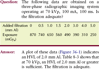
As was discussed in Chapter 8, it is not normally possible physically to examine and measure the thickness of each component of total filtration. An accurate measurement of half-value layer (HVL) is sufficient. If the HVL is equal to or greater than the values given in Table 8-3 at various kVp levels, total filtration is adequate.
Reproducibility
For any given radiographic technique, the output radiation intensity should be constant from one exposure to another. This is checked by making repeated radiation exposures through the same technique and observing the average variation in radiation intensity.
Linearity
When adjacent mA stations are used, for example, 100 mA and 200 mA, and exposure time is adjusted for constant mAs, the output radiation intensity should remain constant. When the exposure time remains constant, causing the mAs to increase in proportion to the increase in mA, radiation intensity should be proportional to mAs.
This takes any inaccuracy in the exposure timer out of the analysis. Radiation intensity is expressed in units of mGya/mAs (mR/mAs).
Operator Shield
It must not be possible to expose an image receptor while the radiologic technologist stands unprotected outside a fixed protective barrier, usually the console booth. The exposure control should be fixed to the operating console and not to a long cord. The radiologic technologist may be in the examination room during exposure, but only if protective apparel is worn.
Mobile X-ray Imaging System
A protective lead apron should be assigned to each mobile x-ray imaging system. The exposure switch of such an imaging system must allow the operator to remain at least 2 m from the x-ray tube during exposure. Of course, the useful beam must be directed away from the radiologic technologist while positioned at this minimum distance.
Fluoroscopic Protection Features
The features of fluoroscopic imaging systems that follow are intended primarily to reduce patient radiation dose. Usually, when patient radiation dose is reduced, personnel exposure is reduced similarly.
Source-to-Skin Distance
One would think that increasing the distance between any x-ray tube and the patient would result in reduced patient dose because of the increased distance. This is true, but to maintain exposure to the image intensifier, the mA must be increased to compensate for the increased distance. Because of the divergence of the x-ray beam, the entrance skin dose (ESD) is lessened for the required exit dose as the source-to-skin (SSD) is increased.
 The SSD must be not less than 38 cm on stationary fluoroscopes and not less than 30 cm on mobile fluoroscopes.
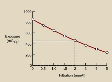
Review Figure 36-2, where a 20-cm abdomen is 5 HVLs thick. If the fluoroscopic x-ray tube is moved from 40 cm SSD to 20 cm SSD, the ESD is greatly increased. The exposure required at the image intensifier is 10 mGya.
FIGURE 36-2 Patient entrance skin exposure (ESE) is considerably higher when the fluoroscopic x-ray tube is too close to the tabletop.
The ESDs will be 22.5 µGya and 40 µGya, respectively, solely because of the divergence of the x-ray beam—the inverse square law. Add the x-ray attenuation of 5 HVLs for each geometry, and the respective ESDs become 0.72 mGyt and 1.28 mGyt (Box 36-1).


Primary Protective Barrier
The fluoroscopic image receptor assembly serves as a primary protective barrier and must be 2 mm Pb equivalent. It must be coupled with the x-ray tube and interlocked so that the fluoroscopic x-ray tube cannot be energized when the image receptor is in the parked position.
Filtration
The total filtration of the fluoroscopic x-ray beam must be at least 2.5 mm Al equivalent. The tabletop, patient cradle, or other material positioned between the x-ray tube and the tabletop are included as part of the total filtration. When the filtration is unknown, the HVL should be measured. The minimum HVL reported in Table 20-3 must be met so that adequate filtration can be assumed.
Collimation
Fluoroscopic x-ray beam collimators must be adjusted so that an unexposed border is visible on the image monitor when the input phosphor of the image intensifier is positioned 35 cm above the tabletop and the collimators are fully open. For automatic collimating devices, such an unexposed border should be visible at all heights above the tabletop. The collimator shutters should track with height above the tabletop.
Exposure Control
The fluoroscopic exposure control should be of the dead man type; that is, if the operator should drop dead or just release the pressure, the exposure would be terminated—unless, of course, he or she falls on the switch! The conventional foot pedal or pressure switch on the fluoroscopic image receptor satisfies this condition.
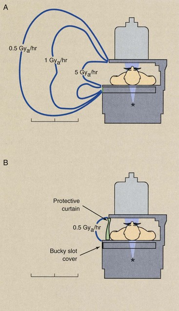
Bucky Slot Cover
During fluoroscopy, the Bucky tray is moved to the end of the examination table, leaving an opening in the side of the table approximately 5 cm wide at gonadal level. This opening should be covered automatically with at least 0.25 mm Pb equivalent.
Protective Curtain
A protective curtain or panel of at least 0.25 mm Pb equivalent should be positioned between the fluoroscopist and the patient. Figure 36-3 shows the typical isoexposure distribution for a fluoroscope. Without the curtain and the Bucky slot cover, the exposure of radiology personnel is many times higher.
Cumulative Timer
A cumulative timer that produces an audible signal when the fluoroscopic time has exceeded 5 minutes must be provided. This device is designed to ensure that the radiologist is aware of the relative beam-on time during each procedure. The assisting radiologic technologist should record total fluoroscopy beam-on time for each examination.
Dose Area Product
The intensity of the x-ray beam at the tabletop of a fluoroscope should not exceed 21 mGya/min (2.1 R/min) for each mA of operation at 80 kVp. If there is no optional high-level control, the intensity must not exceed 100 mGya/min (10 R/min) during fluoroscopy. If an optional high-level control is provided, the maximum tabletop intensity allowed is 200 mGya/min (20 R/min). There is no limit on x-ray intensity when the image is recorded, as in cineradiography or videography.
The overall stochastic risk to a patient depends on effective radiation dose (E), which is related to tissue radiation dose and to the volume of tissue exposed. Tissue radiation dose, which refers to the energy deposited locally, is the quantity that best reflects the potential for injury to that tissue (deterministic effect).
Dose area product (DAP) is a quantity that reflects not only the dose but also the volume of tissue irradiated; therefore, it may be a better indicator of risk than dose. DAP is expressed in cGy-cm2 (R-cm2).
DAP increases with increasing field size even if the dose remains unchanged. Smaller field size results in lower DAP, and thus less risk, because a smaller amount of tissue is exposed.
DAP may be used to monitor radiation output from radiographic and fluoroscopic imaging systems. DAP meters are becoming more common on x-ray imaging systems. Typically, the radiolucent device is placed near the x-ray source below the collimator, before the beam enters the patient.
The risk for injury to the skin where the beam enters the patient can be derived by dividing the DAP measurement by the area of the beam at the skin. Using DAP to monitor radiation intensity is a good way to implement radiation management procedures and keep patient exposures low.
Design of Protective Barriers
In designing a radiology department or an individual x-ray examination room, it is not sufficient to consider only general architectural characteristics. Great attention must be given to the location of the x-ray imaging system in the examination room.
The use of adjoining rooms is also of great importance when the design is geared toward radiation safety. It is often necessary to include protective barriers, usually sheets of lead, in the walls of x-ray examination rooms. If the radiology facility is located on an upper floor, then it may be necessary to shield the floor as well.
A great number of factors are considered when a protective barrier is designed. This discussion touches only on the fundamentals and some basic definitions. Whenever new x-ray facilities are being designed or old ones renovated, a medical physicist must be consulted for assistance in the design of proper radiation shielding.
Type of Radiation
For the purpose of protective barrier design, three types of radiation are considered (Figure 36-4). Primary radiation is the most intense and therefore the most hazardous and the most difficult to shield.
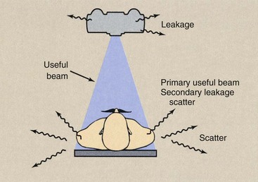
FIGURE 36-4 Three types of radiation—the useful beam, leakage radiation, and scatter radiation—must be considered when the protective barriers of an x-ray room are designed.
When a chest board is positioned on a given wall, it is sometimes necessary to provide shielding directly behind the chest board, in addition to that specified for the rest of the wall. Any wall to which the useful beam can be directed is designated a primary protective barrier.
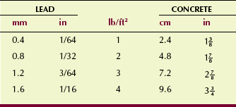
Lead bonded to sheet rock or wood paneling is used most often as a primary protective barrier. Such lead shielding is available in various thicknesses and is specified for architects and contractors in units of pounds per square foot (lb/ft2).
Concrete, concrete block, or brick may be used instead of lead. As a rule of thumb, 4 inches of masonry is equivalent to 1/16 inch of lead. Table 36-1 shows available lead thicknesses and equivalent thicknesses of concrete.
There are two types of secondary radiation: scatter radiation and leakage radiation. Scatter radiation results when the useful beam intercepts any object, causing some x-rays to be scattered. For the purpose of protective shielding calculations, the scattering object can be regarded as a new source of radiation. During radiography and fluoroscopy, the patient is the single most important scattering object.
The intensity of scatter radiation 1 m from the patient is approximately 0.1% of the intensity of the useful beam at the patient.
| Question: | The patient ESD is 4.1 mGya (410 mR) for a kidney, ureter, and bladder (KUB) examination. What will be the approximate radiation exposure at 1 m from the patient? At 3 m from the patient? |
| Answer: | At 1 m: 4.1 µGya × 0.1% = 4.1 mGya × 0.001 = 4.1 µGya At 3 m: 4.1 mGya × (1/3)2 = 4.1 µGya (1/9) = 0.46 µGya |
Leakage radiation is that radiation emitted from the x-ray tube housing in all directions other than that of the useful beam. If the x-ray tube housing is designed properly, the leakage radiation will never exceed the regulatory limit of 1 mGya/hr (100 mR/hr) at 1 m. Although in practice, leakage radiation levels are much lower than this limit, 1 mGya/hr at 1 m is used for protective barrier calculations.
Protective barriers designed to shield areas from secondary radiation are called secondary protective barriers. Secondary protective barriers are always less thick than primary protective barriers.
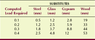
Often, lead is not required for secondary protective barriers because the computation usually results in less than 0.4 mm Pb. In such cases, conventional gypsum board, glass, or lead acrylic is adequate.
Many walls that are secondary protective barriers can be protected adequately with four thicknesses of 5/8-inch gypsum board. Operating console barriers are secondary protective barriers—the useful beam is never directed at the operating console booth. Four thicknesses of gypsum board and 1/2-inch plate glass may be all that is necessary. Sometimes glass walls 1/2 to 1 inch thick can be used as control booth barriers. Table 36-2 gives equivalent thicknesses for secondary protective barrier materials.
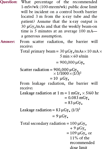
This analysis is representative of the clinical environment. The estimated exposure occurs to the control booth barrier—not to the radiologic technologist. The composition of the barrier and the additional distance reduce technologist exposure even further. This is the reason why personnel radiation exposure during radiography is very low.
Factors That Affect Barrier Thickness
Many factors must be taken into consideration when the required protective barrier thickness is calculated. A thorough discussion of these factors is beyond the scope of this book; however, a definition of each is useful for an understanding of the problems involved.
Distance
The thickness of a barrier naturally depends on the distance between the source of radiation and the barrier. The distance is that to the adjacent occupied area, not to the inside of the wall of the x-ray room.
A wall along which an x-ray imaging system is positioned probably requires more shielding than the other walls of the room. In such a case, the leakage radiation may be more hazardous than the scatter radiation or even the useful beam. It may be desirable to position the x-ray imaging system in the middle of the room because then no single wall is subjected to especially intense radiation exposure.
Occupancy
The use of the area that is being protected is of principal importance. If the area were a rarely occupied closet or storeroom, the required shielding would be less than if it were an office or laboratory that was occupied 40 hours per week.
This concept reflects the time of occupancy factor (T). Table 36-3 reports the occupancy levels of various areas as suggested by the National Council on Radiation Protection and Measurements (NCRP).
TABLE 36-3
Levels of Occupancy of Areas That May Be Adjacent to X-ray Rooms, as Suggested by the NCRP
| Occupancy | Area |
| Full | Work areas (e.g., offices, laboratories, shops, wards, and nurses’ stations), living quarters, children’s play areas, and occupied space in nearby buildings |
| Frequent | Corridors, restrooms, patient rooms |
| Occasional | Waiting rooms, stairways, unattended elevators, janitors’ closets, outside area |
Control
An area that is occupied primarily by radiology personnel and patients is called a controlled area. The design limits for a controlled area are based on the recommended occupational dose limit; therefore, the barrier is required to reduce the exposure to a worker in the area to less than 1 mSv/wk (100 mrem per week).
Design limits for a controlled area are based on the annual recommended occupational dose limit of 50 mSv/yr.
An uncontrolled area can be occupied by anyone; therefore, the maximum exposure rate allowed is based on the recommended dose limit for the public of 1 mSv/yr (100 mrem/yr). This is equivalent to 20 µSv/wk (2 mrem/wk), which is the design limit for an uncontrolled area. Furthermore, the protective barrier should ensure that no individual will receive more than 25 µSv (2.5 mrem) in any single hour.
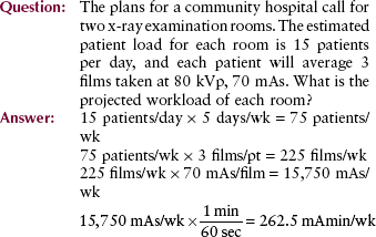
Workload
The shielding required for an x-ray examination room depends on the level of radiation activity in that room. The greater the number of examinations performed each week, the thicker the shielding that is required.
This characteristic is called workload (W) and is expressed in units of milliampere-minutes per week (mAmin/wk). A busy, general purpose x-ray room may have a workload of 500 mAmin/wk. Rooms in private offices have workloads of less than 100 mAmin/wk.
For combination radiographic/fluoroscopic imaging systems, usually only the radiographic workload need be considered for barrier calculations. When the fluoroscopic x-ray tube is energized, a primary protective barrier in the form of the fluoroscopic screen always intercepts the useful x-ray beam. Consequently, the primary barrier requirements are always much less for fluoroscopic x-ray beams than for radiographic x-ray beams.
Use Factor
The percentage of time during which the x-ray beam is on and directed toward a particular protective barrier is called the use factor (U) for that barrier. The NCRP recommends that walls be assigned a use factor of 1/4 and the floor a use factor of 1.
Studies have shown these recommendations to be high and therefore very conservative. Many medical physicists suggest that primary barriers in fact do not exist. All barriers are secondary because the useful beam always is intercepted by the patient and the image receptor.
If an x-ray room has a special design, other use factors may be assigned. A room designed strictly for chest radiography has one wall with a use factor of 1. All others have a use factor of zero for primary radiation and thus would be considered secondary radiation barriers.
The ceiling nearly always is considered a secondary protective barrier. For a secondary barrier, leakage and scatter radiation are present 100% of the time that the x-ray tube is energized.
kVp
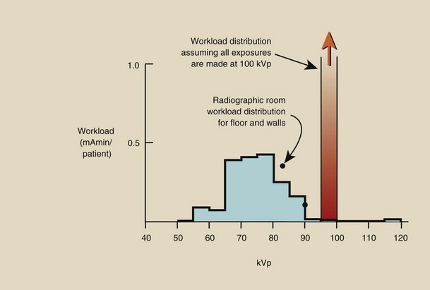
The final consideration in the design of an x-ray protective barrier is the penetrability of the x-ray beam. For protective barrier calculations, kVp is used as the measure of penetrability. Most modern x-ray imaging systems are designed to operate at up to 150 kVp. Most examinations, however, are conducted at an average of 75 kVp.
Usually, constant operation is assumed at a kVp greater than that actually used: 100 kVp for general radiography, 30 kVp for mammography. Therefore, it is more likely that the protective barrier will be too thick than too thin.
Alternatively, a workload distribution such as those shown in Figure 36-5 may be used. Workload distribution results in a more precise determination of required barrier thickness, but it is a considerably more difficult computation to perform.
Measurements of radiation exposure outside the x-ray examination room always result in radiation levels far less than those anticipated by calculation. The total beam-on time is always less than that assumed. The average kVp is usually closer to 75 kVp than to 100 kVp.
Calculations do not account for the fact that the patient and the image receptor always intercept the useful beam. Therefore, although the calculations are intended to result in a dose limit of 1 mSv/wk (100 mrem/wk) or 20 µSv/wk (2 mrem/wk) outside the x-ray room, rarely will the actual exposure exceed 1/10 of those dose limits. To confirm this for yourself, keep records for 1 week of kVp, mAs, and beam direction.
Radiation Detection and Measurement
Instruments are designed to detect radiation or to measure radiation, or to do both. Those designed for detection usually operate in the pulse or rate mode and are used to indicate the presence of radiation. In the pulse mode, the presence of radiation is indicated by a ticking, chirping, or beeping sound. In the rate mode, the instrument response is expressed in mGya/hr (mR/hr) or Gya/hr (R/hr).
Instruments designed to measure the intensity of radiation usually operate in the integrate mode. They accumulate the signal and respond with a total exposure (mGya or Gya). Such application is called dosimetry, and the radiation measuring devices are called dosimeters.
The earliest radiation detection device was the photographic emulsion; it is still a primary means of radiation detection and measurement. However, other devices have been developed that have more favorable characteristics than the photographic emulsion for some applications. Table 36-4 lists most of the currently available radiation detection and measurement devices, along with some of their principal characteristics and uses.
TABLE 36-4
Radiation Detection and Measuring Device Characteristics and Uses
| Device | Characteristics—Uses |
| Photographic emulsion | Limited range, sensitive, energy dependent—personnel monitoring |
| Ionization chamber | Wide range, accurate, portable—survey for radiation levels 10 µGya/hr |
| Proportional counter | Laboratory instrument, accurate, sensitive—assay of small quantities of radionuclides |
| Geiger-Muller counter | Limited to 1 mGya/hr, portable—survey for low radiation levels and radioactive contamination |
| Thermoluminescence dosimetry | Wide range, accurate, sensitive—personnel monitoring, stationary, area monitoring |
| Optically stimulated luminescence dosimetry | Wide range, accurate, sensitive—newest personnel monitoring device |
| Scintillation detection | Limited range, very sensitive, stationary or portable instruments—photon spectroscopy |
It is apparent that film has two principal applications in diagnostic radiology: the making of a radiograph and the radiation monitoring of personnel (film badge). The photographic process was discussed in Chapter 12. Use of film as a radiation monitor is covered in Chapter 37.
Four other types of radiation detection devices are of particular importance in diagnostic radiology. The gas-filled radiation detector is used widely as a device to measure radiation intensity and to detect radioactive contamination. Thermoluminescence dosimetry (TLD) and optically stimulated luminescence (OSL) dosimetry are used for both patient and personnel radiation monitoring. Scintillation detection is the basis for the gamma camera, an imaging device used in nuclear medicine; it is also used in computed tomography (CT) and digital radiography imaging systems.
Gas-Filled Detectors
Three types of gas-filled radiation detectors are used: ionization chambers, proportional counters, and Geiger-Muller detectors. Although these are different in terms of response characteristics, each is based on the same principle of operation. As radiation passes through gas, it ionizes atoms of the gas. The electrons released in ionization are detected as an electrical signal that is proportional to the radiation intensity.
Consider an ideal gas-filled detector as shown schematically in Figure 36-6. It consists of a cylinder filled with air or any of a number of other gases.
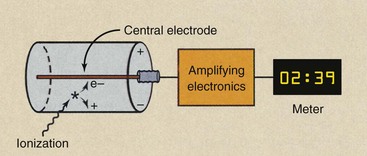
FIGURE 36-6 The ideal gas-filled detector consists of a cylinder of gas and a central collecting electrode. When a voltage is maintained between the central electrode and the wall of the chamber, electrons produced in ionization can be collected and measured.
Along the central axis of the cylinder a rigid wire called the central electrode is positioned. If a voltage is impressed between the central electrode and the wall such that the wire is positive and the wall negative, then any electrons liberated in the chamber by ionization will be attracted to the central electrode.
These electrons form an electrical signal, either as a pulse of electrons or as a continuous current. This electric signal then is amplified and measured. Its intensity is proportional to the radiation intensity that caused it.
In general, the larger the chamber, the more gas molecules are available for ionization, and therefore, the more sensitive is the instrument. Similarly, if the chamber is pressurized, then a greater number of molecules are available for ionization, and even higher sensitivity results.
Sensitivity is not the same as accuracy. A high level of accuracy means that an instrument can detect and precisely measure the intensity of a radiation field. Instrument accuracy is controlled by the overall electronic design of the device.
Region of Recombination
If the voltage across the chamber of the ideal gas-filled detector is increased slowly from zero to a high level, the resulting electrical signal in the presence of fixed radiation intensity will increase in stages (Figure 36-7). During the first stage, when the voltage is very low, no electrons are attracted to the central electrode. The ion pairs produced in the chamber recombine. This is known as the region of recombination, shown as stage R in Figure 36-7.
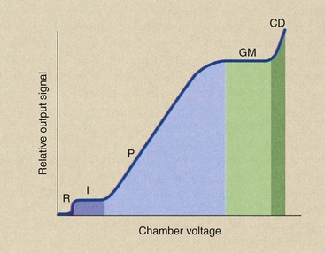
Ion Chamber Region
As the chamber voltage is increased, a condition is reached whereby every electron released by ionization is attracted to the central electrode and collected. The voltage at which this occurs varies according to the design of the chamber, but for most conventional instruments, it occurs in the range of 100 to 300 V.
This portion of the gas-filled detector performance curve is known as the ionization region, indicated by I in the Figure 36-7. Ion chambers are operated in this region.
Several different types of ion chambers are used in radiology; the most familiar of these is the portable survey instrument (Figure 36-8). This instrument is used principally for area radiation surveys. It can measure a wide range of radiation intensities, from 10 µGya/hr (1 mR/hr) to several thousand Gya/hr (R/hr).
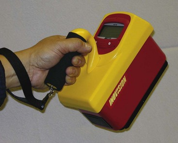
FIGURE 36-8 This portable ion chamber survey instrument is useful for radiation surveys when exposure levels are in excess of 10 µGya/hr. (Courtesy Cardinal Health, Inc.)
The ion chamber is the instrument of choice for measuring radiation intensity in areas around a fluoroscope, around radionuclide generators and syringes, in the vicinity of patients with therapeutic quantities of radioactive materials, and outside of protective barriers. Other, more accurate ion chambers are used for precise calibration of the output intensity of diagnostic x-ray imaging systems (Figure 36-9).
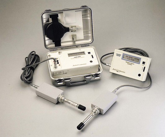
FIGURE 36-9 This ion chamber dosimeter is used for accurate measurement of diagnostic x-ray beams. (Courtesy Radcal Corp.)
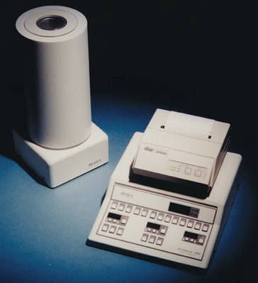
Another application of a precision ion chamber is the dose calibrator (Figure 36-10). These devices find daily use in nuclear medicine laboratories for the assay of radioactive material.
Proportional Region
As the chamber voltage of the ideal gas-filled detector is increased still farther above the ionization region, electrons of the filling gas released by primary ionization are accelerated more rapidly to the central electrode. The faster these electrons travel, the greater is the probability that they will produce additional ionization on their way to the central electrode. These additional ionizations result in additional electrons called secondary electrons.
Secondary electrons also are attracted to the central electrode and collected. The total number of electrons collected in this fashion increases with increasing chamber voltage. The result is a rather large electron pulse for each primary ionization. This stage of the voltage response curve is known as the proportional region.
Proportional counters are sensitive instruments that are used primarily as stationary laboratory instruments for the assay of small quantities of radioactivity. One characteristic of proportional counters that makes them particularly useful is their ability to distinguish between alpha and beta radiation. Nevertheless, proportional counters find few applications in clinical radiology.
Geiger-Muller Region
The fourth region of the voltage response curve for the ideal gas-filled chamber is the Geiger-Muller (G-M) region. This is the region in which Geiger counters operate.
In the G-M region, the voltage across the ionization chamber is sufficiently high that, when a single ionizing event occurs, a cascade of secondary electrons is produced in a fashion similar to a very brief, yet violent, chain reaction. The effect is that nearly all molecules of the gas are ionized, liberating a large number of electrons. This results in a large electron pulse.
When sequential ionizing events occur soon after one another, the detector may not be capable of responding to a second event if the filling gas has not been restored to its initial condition. Therefore, a quenching agent is added to the filling gas of the Geiger counter to enable the chamber to return to its original condition; subsequent ionizing events then can be detected. The minimum time between ionizations that can be detected is known as the resolving time.
Geiger counters are used for contamination control in nuclear medicine laboratories. As portable survey instruments, they are used to detect the presence of radioactive contamination on work surfaces and laboratory apparatus.
They are not particularly useful as dosimeters because they are difficult to calibrate for varying conditions of radiation. Geiger counters are sensitive instruments that are capable of detecting and indicating single ionizing events. If they are equipped with an audio amplifier and a speaker, one can even hear the crackle of individual ionizations.
The Geiger counter does not have a very wide range. Most instruments are limited to less than 1 mGya/hr (100 mR/hr).
Region of Continuous Discharge
If the voltage across the gas-filled chamber is increased still further, a condition is reached whereby a single ionizing event completely discharges the chamber, as in operation in the G-M region. Because of the high voltage, however, electrons continue to be stripped from atoms of the filling gas, producing a continuous current or signal from the chamber.
In this condition of continuous discharge, the instrument is useless for the detection of radiation, and continued operation in this region results in damage. The region of continuous discharge is indicated as CD in Figure 36-7.
Scintillation Detectors
Scintillation detectors are used in several areas of radiologic science. The scintillation detector is the basis for the gamma camera in nuclear medicine and is used in the detector arrays of CT imaging systems; it is the image receptor for several types of digital imaging systems.
The Scintillation Process
Some types of material scintillate when irradiated, that is, they emit a flash of light immediately in response to absorption of an x-ray. The amount of light emitted is proportional to the amount of energy absorbed by the material.
Consider, for example, the two x-ray interactions diagrammed in Figure 36-11. If a 50-keV x-ray interacts photoelectrically in the crystal, all the energy (50 keV) will reappear as light. If, however, that same x-ray interacts through a Compton scattering event in which only 20 keV of energy is absorbed, then a proportionately lower quantity of light will be emitted in the scintillation.
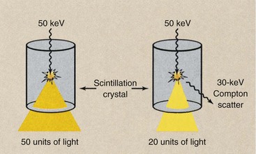
FIGURE 36-11 During scintillation, the intensity of light emitted is proportional to the amount of energy absorbed in the crystal.
Only those materials with a particular crystalline structure scintillate. At the atomic level, the process involves the rearrangement of valence electrons into traps. The return of the electron from the trap to its normal position is immediate in scintillation and delayed in luminescence. This property was considered under an earlier discussion of luminescence (see Chapter 12).
Types of Scintillation Phosphors
Many different types of liquids, gases, and solids can respond to ionizing radiation by scintillation. Scintillation detectors are used most often to indicate individual ionizing events and are incorporated into fixed or portable radiation detection devices. They can be used to measure radiation in the rate mode or the integrate mode.
Nearly all the noble gases can be made to respond to radiation by scintillation. Such applications are rare, however, because the detection efficiency is very low and the probability of interaction therefore is small.
Liquid scintillation detectors are used frequently in the research laboratory to detect low-energy beta emissions from carbon-14 (14C) and tritium (3H). Because they present a relatively harmless radiation hazard and are incorporated easily into biologic molecules, 14C and 3H are useful research radionuclides.
These radionuclides emit low-energy beta particles with no associated gamma rays. This makes them difficult to detect. With liquid scintillation counting, however, biologic molecules can be mixed with a liquid scintillation phosphor so that the beta emission interacts directly with the phosphor, causing a flash of light to be emitted. Liquid scintillation counters have nearly 100% detection efficiency for beta radiation.
By far, the most widely used scintillation phosphors are the inorganic crystals—thallium-activated sodium iodide (NaI : Tl) and thallium-activated cesium iodide (CsI : Tl). The activator atoms of thallium are impurities grown into the crystal to control the spectrum of the light emitted and to enhance its intensity.
NaI : Tl crystals are incorporated into gamma cameras; CsI : Tl is the phosphor that is incorporated into image-intensifier tubes as the input phosphor and into flat panel digital radiography image receptors. Both types of crystals have been incorporated into CT imaging system detector arrays. However, many of today’s CT imaging systems use cadmium tungstate (CdWO4) or a ceramic as the scintillation detector.
The Scintillation Detector Assembly
Light produced during scintillation is emitted isotopically, that is, with equal intensity in all directions. Consequently, when used as radiation detectors, scintillation crystals are enclosed in aluminum with a polished inner surface in contact with the crystal. This allows the light flash to be reflected internally to the one face of a crystal that is not enclosed, which is called the window.
Aluminum containment is also necessary to seal the crystal hermetically. A hermetic seal is one that prevents the crystal from coming into contact with air or moisture. This is necessary because many scintillation crystals are hygroscopic, that is, they absorb moisture. When moisture is absorbed, the crystals swell and crack. Cracked crystals are not useful because the crack produces an interface that reflects and attenuates the scintillation.
Figure 36-12 shows the basic components of a single crystal–photomultiplier (PM) tube assembly representative of the type used in the portable survey instrument. The detector portion of the assembly is the NaI : Tl crystal contained in the aluminum hermetic seal. Coupled to the window of the crystal is a PM tube that converts light flashes from the scintillator into an electrical signal of pulses.
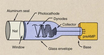
FIGURE 36-12 Scintillation detector assembly characteristics of the type used in a portable survey instrument.
 Photomultiplier Tube Gain
The PM tube is an electron vacuum tube that contains a number of elements. The tube consists of a glass envelope, which provides structural support for the internal elements and maintains the vacuum inside the tube.
The portion of the glass envelope that is coupled to the scintillation crystal is called the window of the tube. The crystal window and the PM tube window are sandwiched together with a silicone grease, which provides optical coupling, so that the light emitted by the scintillator is transmitted to the interior of the PM tube with minimum loss.
As light passes from the crystal into the PM tube, it is incident on a thin metal coating called a photocathode, which consists of a compound of cesium, antimony, and bismuth. Electrons are emitted from the photocathode by a process called photoemission, which is similar to thermionic emission in the filament of an x-ray tube, except that the stimulus is light rather than heat.
The flash of light from the scintillation crystal therefore is incident on the photocathode, and electrons are released by photoemission. The number of electrons emitted is directly proportional to the intensity of the light.
These photoelectrons are accelerated to the first of a series of plate-like elements called dynodes. Each dynode serves to amplify the electron pulse through secondary electron emission. For each electron incident on the dynode, several secondary electrons are emitted and directed to the next stage. Consequently, an electron gain occurs for each dynode in the PM tube.
The number of dynodes and the gain of each dynode determine the overall electron gain of the PM tube. Photomultiplier tube gain is the dynode gain raised to the power of the number of dynodes.
| Question: | An eight-stage PM tube (eight dynodes) has a dynode gain of three (three electrons emitted for each incident electron). What is the PM tube gain? |
| Answer: | PM tube gain = 38 = 6561 |
The last plate-like element of the PM tube is the collecting electrode or collector. The collector absorbs the electron pulse from the last dynode and conducts it to the preamplifier. The preamplifier provides an initial state of pulse amplification. It is attached to the base of the PM tube, a structure that provides support for the glass envelope and internal structures.
The overall result of scintillation detection is that a single photon interaction produces a burst of light; this, in turn, produces photoelectron emission, which then is amplified to produce a relatively large electron pulse.
The size of the electron pulse is proportional to the energy absorbed by the crystal from the incident photon.
It is this property of scintillation detection that promotes its use as an energy-sensitive device for gamma spectrometry that uses pulse height analysis. Through such an application, unknown gamma emitters can be identified and more sensitive radioisotope imaging can be accomplished by counting only those pulses with energy that represents total gamma ray absorption.
Scintillation detectors are sensitive devices for x-rays and gamma rays. They are capable of measuring radiation intensities as low as single-photon interactions. This property of scintillation detectors results in their use as portable radiation devices in much the same manner as Geiger counters are used.
A portable scintillation detector is more sensitive than a Geiger counter because it has much higher detection efficiency. For this application, the scintillation detector would be used to monitor the presence of contamination and perhaps low levels of radiation.
Thermoluminescence Dosimetry
Some materials glow when heated, thus exhibiting thermally stimulated emission of visible light, called thermoluminescence. In the early 1960s, Cameron and coworkers at the University of Wisconsin experimented with some thermoluminescent materials and were able to show that exposure to ionizing radiation caused some materials to glow particularly brightly when subsequently heated.
Radiation-induced thermoluminescence has been developed into a sensitive and accurate method of radiation dosimetry for personnel radiation monitoring and for measurement of patient dose during diagnostic and therapeutic radiation procedures. Personnel and patient radiation monitoring is discussed later; however, at this time, it is important to discuss some of the basic principles of TLD (Figure 36-13).
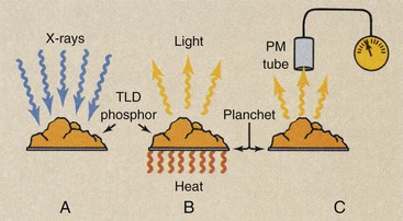
FIGURE 36-13 Thermoluminescence dosimetry is a multistep process. A, Exposure to ionizing radiation. B, Subsequent heating. C, Measurement of the intensity of emitted light.
After irradiation, the TLD phosphor is placed on a special dish or planchet for analysis in an instrument called a TLD analyzer. The temperature of the planchet can be controlled carefully. Directly viewing the planchet is a PM tube. The PM tube is the same type of light-sensitive and light-measuring vacuum tube that was described previously as a major component of scintillation detectors.
The PM tube–planchet assembly is placed in a chamber with a light-tight seal. The output signal from the PM tube is amplified and displayed.
The Glow Curve
As the temperature of the planchet is increased, the amount of light emitted by the TLD increases in an irregular manner. Figure 36-14 shows the light output from lithium fluoride (LiF) as temperature increases. Several prominent peaks can be seen on the graph; each occurs because of a specific electron transition within the thermoluminescent crystals.
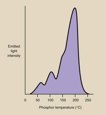
Such a graph is known as a glow curve; each type of thermoluminescent material has a characteristic glow curve. The height of the highest temperature peak and the total area under the curve are directly proportional to the energy deposited in the TLD by ionizing radiation. TLD analyzers are electronic instruments that are designed to measure the height of the glow curve or the area under the curve and relate this to exposure or dose through a conversion factor.
Types of Thermoluminescence Dosimetry Material
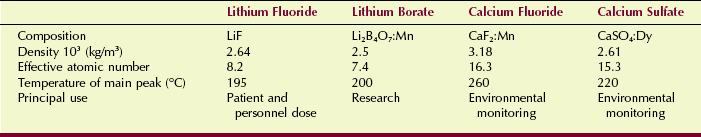
Many materials, including some body tissues, exhibit the property of radiation-induced thermoluminescence. Materials that are used for TLD, however, are somewhat limited in number and are principally types of inorganic crystals. Lithium fluoride (LiF) is the most widely used TLD material. It has an atomic number of 8.2 and therefore exhibits x-ray absorption properties similar to those of soft tissue.
LiF is relatively sensitive. It can measure doses as low as 50 µGyt (5 mrad) with modest accuracy, and at doses exceeding 100 mGyt (10 rad), its accuracy is better than 5%.
Calcium fluoride (CaF2) activated with manganese (CaF2:Mn) has a higher effective atomic number (Z = 16.3) than LiF; this makes it considerably more sensitive to ionizing radiation. CaF2:Mn can measure radiation doses of less than 10 µGyt (1 mrad) with moderate accuracy. Other types of TLDs are available; Table 36-5 lists some thermoluminescent phosphors and their principal characteristics and applications.
Properties of Thermoluminescence Dosimetry
A particular advantage of TLD is size. The TLD can be obtained in several solid crystal shapes and sizes. Rectangular rods measuring 1 × 1 × 6 mm and flat chips measuring 3 × 1 mm are the most popular sizes. The TLD also can be obtained in powder form; this allows irradiation in nearly any configuration. TLDs are also available with the phosphor matrixed with Teflon or plated onto a wire and sealed in glass.
The TLD is reusable. With irradiation, the energy absorbed by the TLD remains stored until released as visible light by heat during analysis. Heating restores the crystal to its original condition and makes it ready for another exposure.
The TLD responds proportionately to dose. If the dose is doubled, the TLD response also is doubled.
The TLD is rugged, and its small size makes it useful for monitoring dose in small areas, such as body cavities. The TLD does not respond to individual ionizing events; therefore, it cannot be used in a rate meter type of instrument. The TLD is suitable only for integral dose measurements, but it does not give immediate results. It must be analyzed after irradiation for dosimetry results.
Optically Stimulated Luminescence Dosimetry
An additional radiation dosimeter especially adapted for personnel monitoring was developed by Landauer in the late 1990s (Figure 36-15). The process is called optically stimulated luminescence (OSL) and uses aluminum oxide (Al2O3) as the radiation detector.
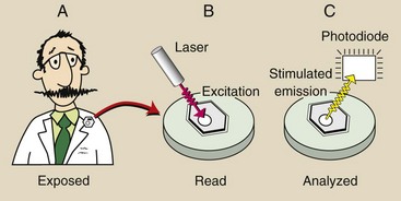
FIGURE 36-15 Optically stimulated luminescence dosimetry is a multistep process. A, Exposure to ionizing radiation. B, Laser illumination. C, Measurement of the intensity of stimulated light emission.
Irradiation of Al2O3 stimulates some electrons into an excited state. During processing, laser light stimulates these electrons, causing them to return to their ground state with the emission of visible light. The intensity of the visible light emission is proportional to the radiation dose received by the Al2O3.
The OSL process is not unlike TLD. Both are based on stimulated luminescence. However, OSL has several advantages over TLD, especially as applied to occupational radiation monitoring.
With a minimum reportable dose of 10 µGyt, OSL is more sensitive than TLD. OSL has a precision of 10 µGyt, which beats TLD. Other features of OSL include reanalysis for confirmation of dose, qualitative information about exposure conditions, wide dynamic range, and excellent long-term stability.
Summary
Many radiation protection devices, accessories, and protocols are associated with modern x-ray imaging systems. This chapter discusses the radiation protection devices that are common to all radiographic and fluoroscopic imaging systems. Many of these devices are federally mandated; others exhibit features added by manufacturers.
Leakage radiation emitted by the x-ray tube during exposure must be contained by a protective x-ray tube housing. The limit of leakage must be no more than 1 mGya per hour at a distance of 1 m from the housing. The control panel must indicate exposure by kVp and mA meters or visible and audible signals.
Great attention is given to the design of radiographic rooms, to the placement of x-ray imaging systems, and to the use of adjoining rooms. Two types of protective barriers are used: primary barriers and secondary barriers. Primary barriers intercept the useful x-ray beam and require the greatest amount of lead or concrete. Secondary barriers protect personnel from scatter and leakage radiation.
Dosimeters are instruments designed to detect and measure radiation. Other than photographic emulsion, four types of highly accurate devices are used to measure radiation. Gas-filled detectors include the ionization chamber, the proportional counter, and the Geiger-Muller counter. The scintillation detector is a very sensitive device that is used in nuclear medicine. Two other radiation detection devices used especially for occupational radiation monitoring are thermoluminescence dosimetry and optically stimulated luminescence dosimetry.
1. Define or otherwise identify the following:
2. What do audible and visible signals indicate on the radiographic control console?
3. List as many devices used for radiation protection on radiographic equipment as you can.
4. What is the result if the x-ray beam and the film are not properly aligned?
5. What filtration is used for mammography equipment operated below 30 kVp?
6. How are reproducibility and linearity different when the intensity of the x-ray beam is measured?
7. What characteristics of fluoroscopic equipment are designed for radiation protection?
8. How can filtration be measured if the amount of inherent and added filtration is unknown?
9. Name the three types of radiation exposure that are of concern when protective barriers are designed.
10. List four factors that are taken into consideration when a barrier for a radiographic room is designed.
11. What is the difference between a controlled area and an uncontrolled area?
12. What are the units of workload for an x-ray examination room?
13. Explain the use factor (U) as it relates to a protective barrier in an x-ray examination room.
14. Why is the use factor for secondary barriers always 1?
15. Name the three gas-filled dosimeters.
16. Discuss the properties of TLD that make it suitable for personnel monitoring.
17. Which modality of diagnostic imaging uses scintillation detection as a radiation detection process?
18. What are the two most widely used scintillation phosphors?
19. A photomultiplier has nine dynodes, each of which has a gain of 2.2. What is the overall tube gain?
20. Given the following conditions of operation, compute the weekly workload:
The answers to the Challenge Questions can be found by logging on to our website at http://evolve.elsevier.com.