Screen-Film Radiographic Quality Control
At the completion of this chapter, the student should be able to do the following:
1 Define quality assurance and quality control.
2 List the 10-step quality assurance model used in hospitals.
3 Name the three steps of quality control.
4 Describe the quality control tests and schedule for screen-film radiographic systems.
ALL FIELDS of medicine and all hospital departments are required to develop and conduct programs that ensure the quality of patient care and management. Diagnostic imaging departments are leaders in promoting quality patient care.
This chapter discusses the properties of quality assurance and quality control with an emphasis on radiographic imaging systems. Processor quality control is covered thoroughly in Chapter 24 (“Mammography Quality Control”) and therefore is only reviewed here.
Two areas of activity are designed to ensure the best possible diagnosis at an acceptable patient radiation dose and with minimum cost. These areas are quality assurance (QA) and quality control (QC). There is still some confusion about the use of these terms, but responsible organizations are developing clearer definitions. Both programs rely heavily on proper recordkeeping.
Quality Assurance
Health care organizations often adopt formal, structured QA models. The Joint Commission (TJC) promotes “The Ten-Step Monitoring and Evaluation Process.” This QA program uses a 10-step process to resolve identified patient care problems. To ensure that health care organizations are committed to providing high-quality services and care, accrediting agencies encourage the adoption of QA models such as that recommended by TJC (Box 20-1).
A program of QA monitors proper patient scheduling, reception, and preparation and answers the following questions: Is the scheduled examination appropriate for the patient? If so, has the patient been properly instructed before the time of the examination?
Item 8 in Box 20-1 leads to programs of continuous quality improvement (CQI); these have been implemented by many health care organizations.
Quality assurance also involves image interpretation. Did the patient’s ultimate disease or condition agree with the radiologist’s diagnosis? This is called outcome analysis. Was the report of the diagnosis promptly prepared, distributed, and filed for subsequent evaluation? Was the clinician or patient properly informed in a timely fashion? All of these QA activities require attention from the imaging team, but they are principally the responsibility of the radiologist and the imaging service management.
Quality Control
Quality control is more tangible and obvious than QA. A program of QC is designed to ensure that the radiologist is provided with an optimal image produced through good equipment performance and resulting in minimal patient radiation dose.
Quality control begins with the x-ray imaging systems used to produce the image and continues with the routine evaluation of image-processing facilities. QC concludes with a dedicated analysis of each image to identify deficiencies and artifacts (along with their causes) and to minimize reexaminations.
Each new piece of radiologic equipment, whether it is x-ray producing or image processing, should be acceptance tested before it is applied clinically. The acceptance test must be done by someone other than the manufacturer’s representative because it is designed to show that the equipment is performing within the manufacturer’s specifications and is producing an acceptable patient radiation dose.
With use, the performance characteristics of all such items of equipment change and may deteriorate. Consequently, periodic monitoring of equipment performance is required. On most systems, annual monitoring is satisfactory unless a major component such as an x-ray tube has been replaced.
When periodic monitoring shows that equipment is not performing as was intended, maintenance or repair is necessary. Preventive maintenance usually makes repair unnecessary.
 An acceptable QC program consists of three steps: acceptance testing, routine performance monitoring, and maintenance.
As with QA, QC requires a team effort, but QC is principally the responsibility of the medical physicist. In private offices, clinics, and hospitals, the medical physicist establishes the QC program and oversees its implementation at a frequency determined by the activity of the institution.
In a large medical center hospital where the medical physicist is a member of the professional staff, he or she performs many of the routine activities and supervises other activities. With the help of the QC technologist and radiologic engineers, the medical physicist sees that all necessary monitoring measurements and observations are performed.
In addition to ensuring quality patient care, a QC program in radiology is conducted for other reasons. Our litigious society demands QC records. Some insurance carriers pay for services only from facilities with approved QC programs. TJC will not place its seal of approval on facilities that do not have an ongoing QC program. Most states, through their Department of Health and with guidance from the Council of Radiation Control Program Directors (CRCPD), require QC by regulation.
Effective January 2012, most insurance companies and the U.S. Center for Medicare and Medicaid Services require accreditation for any advanced diagnostic imaging (ADI) such as CT, MRI, SPECT, and PET for payment for such studies. The accrediting organizations are the American College of Radiology, the Intersocietal Accreditation Commission, RadSite by HealthHelp, and TJC. All require robust QC programs.
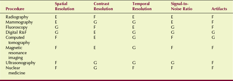
The nature of a QC program is determined somewhat by the characteristics of the image produced. Table 20-1 summarizes the characteristic features of most imaging systems. Usually, the QC program focuses on the strengths of the image to ensure that those strengths are maintained.
Screen-Film Radiographic Quality Control
Organizations such as the American College of Radiology and the American Association of Physicists in Medicine have developed guidelines for QC programs in radiography, as well as other diagnostic imaging modalities.
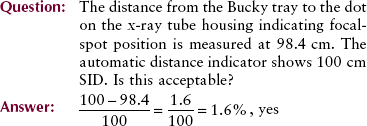
Table 20-2 presents the essentials of such a program, the recommended frequency of evaluation, and the tolerance limit for each assessment. Figure 20-1 shows a medical physicist preparing dosimetry equipment for QC measurements.
TABLE 20-2
Elements of a Quality Control Program for Radiographic Systems
| Measurement | Frequency* | Tolerance |
| Filtration | Annually | ≥2.5 mm Al |
| Collimation | Semiannually | ±2% SID |
| Focal-spot size | Annually | ±50% |
| Calibration of kVp | Annually | ±10% |
| Exposure timer accuracy | Annually | ±5% >10 ms ±20% ≤10 ms |
| Exposure linearity | Annually | ±10% |
| Exposure reproducibility | Annually | ±5% |
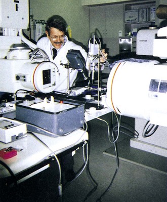
FIGURE 20-1 Medical physicist preparing for quality control (QC) measurements. (Courtesy Louis Wagner, University of Texas Medical School.)
Filtration
Perhaps the most important patient protection characteristic of a radiographic imaging system is filtration of the x-ray beam. State statutes require that general-purpose radiographic units have a minimum total filtration of 2.5 mm Al.
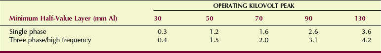
It is normally not possible to measure filtration directly, so one resorts to measurement of the half-value layer (HVL) of the x-ray beam, as described in Chapter 8. The measured HVL must meet or exceed the value shown in Table 20-3 for the total filtration to be considered adequate. Filtration should be evaluated annually or at any time after a change has occurred in the x-ray tube or tube housing.
Collimation
The x-ray field must coincide with the light field of the variable-aperture light-localizing collimator. If these fields are misaligned, the intended anatomy will be missed and unintended anatomy irradiated. Adequate collimation can be confirmed with any of a number of test tools designed for that purpose (Figure 20-2).
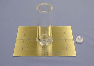
FIGURE 20-2 A test tool for monitoring the coincidence of the x-ray beam and light field. (Courtesy Cardinal Health.)
Most systems today are equipped with positive beam–limiting (PBL) collimators. These devices are automatic collimators that sense the size of the image receptor and adjust the collimating shutters to that size.
Because different sizes of image receptors must be accommodated, the PBL function must be evaluated for all possible receptor sizes. With a PBL collimator, the x-ray beam must not be larger than the image receptor except in the override mode.
Distance and centering indicators must be accurate to within 2% and 1% of the source-to-image receptor distance (SID), respectively. The distance indicator can be checked simply with a tape measure. The location of the focal spot usually is marked on the x-ray tube housing. Centering is checked visually for the light field and with markers for the exposure field.
Focal-Spot Size
The spatial resolution of a radiographic imaging system is determined principally by the focal-spot size of the x-ray tube. When new equipment or a replacement x-ray tube is installed, the focal-spot size must be measured (Figure 20-3).
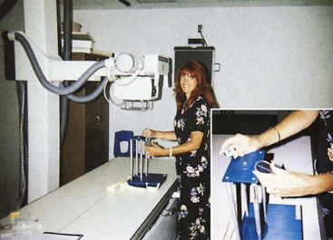
FIGURE 20-3 The pinhole camera, star pattern, and slit camera may be used to measure focal-spot size. (Courtesy Teresa Rice, Houston Community College.)
Three tools are used for measurement of focal-spot size: the pinhole camera, the star pattern, and the slit camera.
The pinhole camera is difficult to use and requires excessive exposure time. The star pattern is easy to use but has significant limitations for focal-spot sizes less than 0.3 mm. The standard for measurement of effective focal-spot size is the slit camera.
The fabrication of an x-ray tube is an exceptionally complex process. Specification of focal-spot size depends not only on the geometry of the tube but also on the focusing of the electron beam. Consequently, vendors are permitted a substantial variance from their advertised focal-spot sizes (see Table 6-2).
Focal-spot size should be evaluated annually or whenever an x-ray tube is replaced.
An acceptable alternative to focal-spot size measurement is use of a line-pair test tool to determine limiting spatial frequency (Figure 20-4).
Kilovolt Peak Calibration
The radiologic technologist selects kilovolt peak (kVp) for every screen-film radiographic examination. Radiologic technologists go to exceptional lengths to determine the appropriate kVp; therefore, the x-ray generator should be properly calibrated.
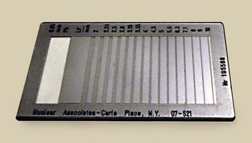
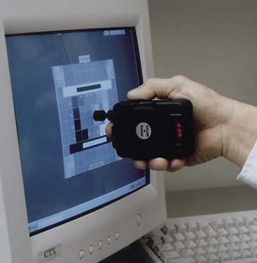
A number of methods are available to evaluate the accuracy of kVp. Today, most medical physicists use one of a number of devices that are based on filtered ion chambers or filtered photodiodes (Figure 20-5). Other methods that use voltage diodes and oscilloscopes are more accurate but require an exceptional amount of time.
FIGURE 20-5 High-voltage (kVp) and other generator functions can be evaluated with compact test devices. (Courtesy Gammex RMI.)
The kVp calibration should be evaluated annually or whenever high-voltage generator components have changed significantly. In the diagnostic range, any change in peak kilovoltage affects patient radiation dose. A variation in kVp of approximately 4% is necessary to affect image optical density and radiographic contrast.
Exposure Timer Accuracy
Exposure time is operator selectable on most radiographic consoles. Although many radiographic systems are phototimed or controlled by milliampere seconds (mAs), exposure time is still the responsibility of radiologic technologists. This parameter is particularly responsible for patient radiation dose and image optical density.
Exposure timer accuracy can be assessed in several ways. Most medical physicists use one of several commercially available products that measure exposure time on the basis of irradiation time of an ion chamber or photodiode assembly (Figure 20-6).
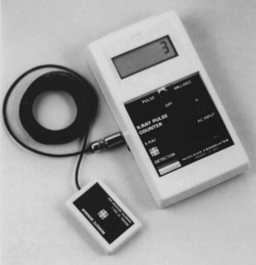
Exposure timer accuracy should be within 5% of the indicated time for exposure times greater than 10 ms.
The accuracy of the exposure timer should be assessed annually or more frequently if a component of the operating console or the high-voltage generator has undergone major repairs. Accuracy of 20% is acceptable for exposure times of 10 ms or less.
Automatic exposure control (AEC) also must be evaluated. These devices are designed to provide a constant optical density regardless of tissue thickness, composition, or failure of the reciprocity law (see Chapter 10). AEC systems are evaluated by exposing an image receptor through various thicknesses of aluminum or acrylic. Regardless of the material thickness and the absolute exposure time, the optical density of the processed image should be constant.
Insertion of a lead filter allows one to adequately assess the functioning of the backup timer. If the phototimer fails, the backup timer should terminate the exposure at 6 s or 600 mAs, whichever occurs first.
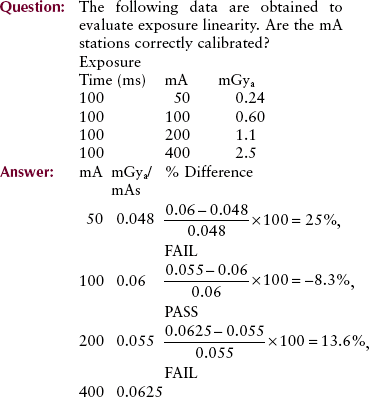
Exposure Linearity
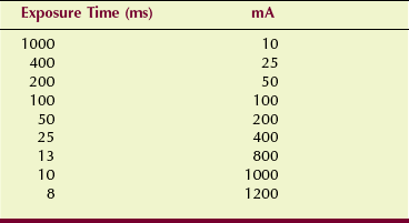
Many combinations of mA and exposure time produce the same mAs value. The ability of a radiographic unit to produce a constant radiation output for various combinations of mA and exposure time is called exposure linearity.
Exposure linearity is determined by a precision radiation dosimeter that measures radiation intensity at various combinations of mA and exposure time. Suppose, for example, that one were to choose 10 mAs for evaluation of the combinations of mA and exposure time shown in Table 20-4. Each of these combinations would be energized, and radiation intensity would be measured.
When evaluated in this fashion, the radiation output for adjacent mA stations should be within 10%. Exposure linearity should be evaluated annually or after any significant change or repair of the operating console or high-voltage generator.
This method of assessing exposure linearity is not valid if the exposure timer is inaccurate. Consequently, most would hold exposure time constant and would vary only the mA. Under these conditions, the mR/mAs value should be within 10% between adjacent mA stations.
Exposure Reproducibility
When selecting the proper kVp, mA, and exposure time for a given examination, the radiologic technologist rightfully expects the image optical density and the contrast to be optimal. If any or all of these technique factors are changed and then returned to the previous value, radiation exposure should be precisely the same. Radiation exposure should be reproducible.
Two methods are available to evaluate exposure reproducibility; both rely on a precision radiation dosimeter. First, one can make a series of at least three exposures at the same technique factors, having changed technique controls between each exposure. If the result is not reproducible, this is usually the result of error in the kVp control. Second, one can select a combination of technique factors and hold them constant for a series of 10 exposures.
Mathematical formulas can be used to determine reproducibility in both instances. These formulas basically require that output radiation intensity should not vary by more than ±5%.
Radiographic Intensifying Screens
Intensifying screens require periodic attention to minimize the appearance of artifacts. Screens should be cleaned with a soft, lint-free cloth and a cleaning solution provided by the manufacturer. The frequency of cleaning depends on the workload in the department but certainly should not occur less often than every other month.
Screen-film contact should be evaluated once or twice a year. This is done by radiographing a wire mesh pattern and analyzing the image for areas of blur (see Figure 12-24). If blur appears, the felt or foam pressure pad under the screen should be replaced. If this does not correct the problem, the cassette should be replaced.
Protective Apparel
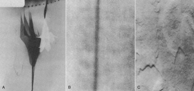
All protective aprons, gloves, and gonadal shields should be radiographed or fluoroscoped annually for defects. If cracks, tears, or holes are evident, the apparel may require replacement (Figure 20-7).
Film Illuminators
Viewbox illumination should be analyzed photometrically on an annual basis. This is done with an instrument called a photometer, which measures light intensity at several areas of the illuminator (Figure 20-8). Intensity should be at least 1500 cd/m2 and should not vary by more than ±10% over the surface of the illuminator. If a bulb requires replacement, all bulbs in that illuminator should be replaced and matched to the type of bulb used in adjacent illuminators.
Tomography Quality Control
In addition to the evaluations performed in the course of QC of a screen-film radiographic system, several measurements are required for those systems that can also perform conventional tomography. Precise performance standards do not exist for conventional tomography. QC measurements are designed to ensure that the characteristics evaluated remain constant.
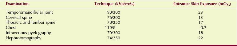
Patient radiation dose should be measured for the most frequent types of tomographic examination. Table 20-5 is a sample of the results from a three-phase system and six representative tomographic examinations.
TABLE 20-5
Exposure Technique and Entrance Skin Exposure During Conventional Tomographic Examination
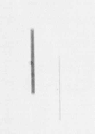
The geometric characteristics of a tomogram can be evaluated with any of a number of test objects designed for this use. Agreement between the indicated section level and the measured level should be within ±5 mm. With incrementing from one tomographic section to the next, the section level should be accurate to within ±2 mm. Constancy of ±1 mm from one QC evaluation to the next should be achieved.
Section uniformity is evaluated by imaging a hole in a lead sheet. The optical density of the screen-film image tracing of the hole should be uniform with no perceptible variations, gaps, or overlaps (Figure 20-9).
Processor Quality Control
Quality control in any activity refers to the routine and special procedures developed to ensure that the final product is of consistently high quality. QC in screen-film radiography requires a planned continuous program of evaluation and surveillance of radiologic equipment and procedures.
When applied to automatic processing, such a program involves periodic cleaning, system maintenance, and daily monitoring. Table 20-6 lists an appropriate processor QC program.
TABLE 20-6
Quality Control Program for Radiographic Film Processor
| Activity | Procedure or Item | Schedule |
| Processor cleaning | Crossover racks | Daily |
| Entire rack assembly and processing ranks | Weekly | |
| Scheduled maintenance | Observation of belts, pulleys, and gears | Weekly |
| Lubrication | Weekly or monthly | |
| Processor monitoring | Planned parts replacement | Regularly |
| Check developer temperature | Daily | |
| Check wash water temperature | Daily | |
| Check replenishment rates | Daily | |
| Sensitometry and densitometry | Daily |
Processor Cleaning
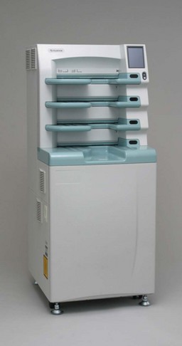
The first automatic processor had a dry-to-drop time of 7 minutes. Soon this was shortened to 3 minutes by what are known as double-capacity processors. Processing time was reduced further with the fast-access system, which is today’s popular 90-second processor (Figure 20-10). Such a processor can handle up to 500 films per hour, but to do so, it requires a high concentration of processing chemistry, a high development temperature 35°C (95°F), and a developer immersion time of 22 seconds.
The wash water temperature should be 31°C (87°F). Earlier automatic processors were supplied with hot and cold water, so the wash temperature was controlled primarily through a mixing valve. Current processors are supplied with only cold water, and temperature is maintained with a thermostatically controlled heater.
This rapid activity, carried on at high temperature with concentrated chemistry, tends to wear and corrode the mechanism of the transport system and contaminate the chemistry with processing sludge. This may lead to a deposit of sludge and debris on the rollers, which can severely affect film quality and cause artifacts if the processor is not properly cleaned at appropriate intervals.
In most facilities, cleaning is conducted weekly; records of such cleaning should be maintained. The cleaning procedure is rather simple. One removes the transport and crossover racks and cleans them and the processing tanks with appropriate fluids (Figure 20-11).
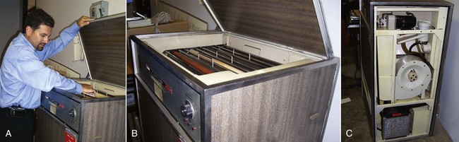
FIGURE 20-11 An automatic processor disassembled for cleaning. (Courtesy Joe Scalise, Merry X-ray Co.)
This takes no longer than a few minutes and pays great dividends in terms of reduced processor wear and consistent production of high-quality radiographs that are artifact free. When all has been reassembled, sensitometric levels must be reestablished.
Processor Maintenance
As with any electromechanical device, maintenance of the film processor is essential. If equipment is not properly maintained, the processor may fail when least expected or when the workload is heaviest. Three types of maintenance programs should be included in the QC program for an automatic film processor.
1. Scheduled maintenance refers to routine procedures that are performed usually weekly or monthly. Such maintenance includes observation of all moving parts for wear; adjustment of all belts, pulleys, and gears; and application of proper lubrication to minimize wear. During processor lubrication, it is especially important to keep the lubricant off your hands, thereby keeping it away from film and rollers and, of course, out of processor chemistry.
2. Preventive maintenance is a planned program of parts replacement at regular intervals. Preventive maintenance requires that a part be replaced before it fails. Such a program should avoid unexpected downtime.
3. Nonscheduled maintenance is, of course, the worst kind. A failure in the system that necessitates processor repair is a nonscheduled event. A proper program of scheduled maintenance and preventive maintenance keeps nonscheduled maintenance to a minimum.
Processor Monitoring
At least once per day, processor operation should be observed and certain measurements recorded. For the most accurate results, this monitoring should occur at the same time every day. The temperature of the developer and wash water should be noted. Developer and fixer replenishment rates should be observed and recorded.
Replenishment tanks should be checked to determine whether the floating lids are properly positioned and whether fresh chemistry is needed. It is often appropriate to check the pH and specific gravity of developer and fixer solutions. Residual hypo should be determined.
A sensitometric strip should be passed through the processor, and fog, speed, and contrast then should be measured and recorded appropriately. Most film suppliers provide forms and assistance to establish and conduct a program of film processor monitoring. A written record of the results of such a program is important.
The processor monitoring approach described in Chapter 24 for the dedicated mammography processor can be applied to all other processors in the health care facility.
Summary
In diagnostic imaging, QA involves the assessment and evaluation of patient care. QC is the measurement and performance evaluation of imaging equipment. Both processes ensure that radiologists are provided with optimal images for proper diagnoses.
The QA and QC team includes radiographers, management and secretarial personnel, the equipment manufacturer’s representative, the medical physicist, radiologic engineers, and radiologists. All accrediting organizations require proper QA and QC programs for approval.
The three steps of QC include (1) acceptance testing, (2) routine performance evaluation, and (3) error correction. Screen-film radiographic QC evaluates filtration, collimation, focal-spot size, kVp, timers, linearity, and reproducibility.
Radiographic intensifying screens are evaluated regularly for cleanliness and screen-film contact. All lead apparel is checked for cracks, tears, and holes. Finally, viewboxes or film illuminators are examined for intensity and cleanliness.
Conventional tomography section sensitivity is evaluated regularly.
Radiographic processor QC is essential for optimal image quality. Sensitometry and densitometry are important daily functions of QC radiologic technologists.
1. Define or otherwise identify the following:
2. List and explain the theory behind the TJC QA program used in hospitals.
3. Discuss the three steps of quality control for screen-film radiographic equipment.
4. Name the people on the diagnostic imaging QC team.
5. How is filtration measured in radiographic equipment?
6. Why are proper x-ray beam alignment and collimation important?
7. What are the limits for radiographic misalignment?
8. What three QC tools are used to measure focal-spot size?
9. What is the permitted variation of radiographic reproducibility?
10. What test is performed on intensifying screens and cassettes to check whether there is proper screen-film contact?
11. What products are used to clean radiographic intensifying screens?
12. How often should lead apparel be checked for protective integrity?
13. How do we ensure kVp accuracy?
14. What is the unit of luminance of a viewbox?
15. How often should an automatic film processor be cleaned?
16. What is the importance of preventive maintenance for a radiographic film processor?
17. A high-frequency radiographic imaging system requires how much x-ray beam filtration?
18. What is the permitted radiographic collimator misalignment?
The answers to the Challenge Questions can be found by logging on to our website at http://evolve.elsevier.com.