CHAPTER 7 Tooth Morphology and Access Cavity Preparation
The hard tissue surrounding the dental pulp can take a variety of configurations and shapes. A thorough knowledge of tooth morphology, careful interpretation of angled radiographs, and adequate access to and exploration of the tooth’s interior are prerequisites for treatment. Magnification and illumination are indispensable aids. This chapter describes and illustrates tooth morphology and explains the techniques crucial to achieving unobstructed direct access to the root canal and apical foramina. This chapter is divided into eight major sections: (1) components of the root canal system, (2) root canal anatomy, (3) anatomy of the apical root, (4) objectives and guidelines for access cavity preparation, (5) mechanical phases of access cavity preparation, (6) challenging access preparations, (7) errors in access cavity preparation, and (8) morphology and access cavity preparations for individual teeth.
Only after correct completion of this phase of therapy can the clinician perform thorough shaping and cleaning and three-dimensional (3-D) obturation. The optimal endodontic result is difficult to achieve if the access is not properly prepared. The clinician must have an understanding of the complexity of the root canal system to understand the principles and problems of shaping and cleaning, to determine the apical limits and dimensions of preparations, to perform microsurgical procedures successfully and to correct procedural errors.
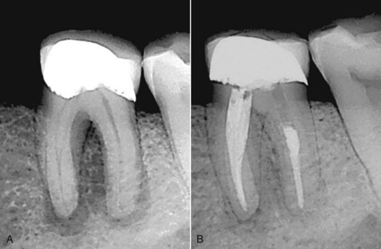
Practitioners must have a thorough understanding of the internal anatomic relationships of teeth and must be able to visualize these relationships before undertaking endodontic therapy. Careful evaluation of two or more periapical radiographs, exposed at different horizontal angulations of the x-ray cone, is mandatory. These radiographs provide important information about root canal morphology. The clinician must keep in mind that the inclination of the x-ray tube significantly influences the ability to detect root canal systems present in premolar teeth. For example, if the horizontal angle is varied by either 20 or 40 degrees, the number of root canals seen in the maxillary first and second premolars and the mandibular first premolars coincides with the number of canals actually present.131 However, in the mandibular second premolar, only the 40-degree horizontal angle correctly identifies the root canal morphology. The critical importance of a careful reading of each radiograph before and during root canal therapy is well recognized. As shown in a case report of five canals in a mandibular first molar, the radiographic appearance significantly aided recognition of the complex canal morphology.69 This study concluded that “any attempt to develop techniques that require fewer radiographs runs the risk of missing information which may be significant for the success of therapy.”
However, conventional radiographs may not always determine the correct morphology, particularly when only a buccolingual view is taken. In one study, 790 extracted mandibular incisors and premolars were radiographed to assess the incidence of canal bifurcation in a root.144 When the fast break guideline was used (i.e., interpreting a sudden disappearance or narrowing of a canal as a sign of canal division [e.g., bifurcation]; Fig. 7-1), the result was failure to diagnose one third of these divisions from a single radiographic view. Thus, evaluation of the root canal system is most accurate when the clinician uses information from several radiographic views together with a thorough clinical exploration of the interior and exterior of the tooth. Alternatively, the recent development of micro-CT has greatly increased our understanding of the complexities and three-dimensional relationships of the root canal systems (see also Chapter 9 and online Chapter 29).
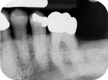
FIG. 7-1 Periapical radiographs can reveal clues to root canal morphology. Abrupt disappearance of the large canal in the mandibular premolars usually signifies a canal bifurcation.
The main objectives of root canal therapy are thorough shaping and cleaning of all pulp spaces and complete obturation of these spaces with an inert filling material. The presence of an untreated canal may be a reason for failure. A canal may go untreated because the clinician fails to detect it. It is extremely important that clinicians use all the armamentaria at their disposal to locate and treat the entire root canal system. The complexity of the spaces that must be accessed, shaped, cleaned, and filled is remarkable. However, even under the most difficult circumstances, current endodontic techniques have an exceptionally high rate of success.
Diagnostic measures are important aids in the location of root canal orifices. These measures include obtaining multiple pretreatment radiographs or cone beam CT (CBCT, see online Chapter 26), examining the pulp chamber floor with a sharp explorer, troughing grooves with ultrasonic tips, staining the chamber floor with 1% methylene blue dye, performing the sodium hypochlorite “champagne bubble” test (Fig. 7-2), and visualizing pulp chamber anatomy108 and root canal bleeding points. Sequential application of 17% aqueous ethylenediaminetetraacetic acid (EDTA) and 95% ethanol (using the Stropko irrigator fitted with a 27-gauge notched irrigating needle) has been recommended for effective cleaning and drying of the pulp chamber floor before visual inspection of the canal system.199
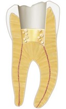
FIG. 7-2 Allowing sodium hypochlorite (NaOCl) to remain in the pulp chamber may help locate a calcified root canal orifice. Tiny bubbles may appear in the solution, indicating the position of the orifice.
An important aid for locating root canals is the dental operating microscope (DOM), which was introduced into endodontics to provide enhanced lighting and visibility (Fig. 7-3). The DOM enhances the clinician’s ability to remove dentin with great precision, thereby minimizing procedural errors. Numerous studies have shown that it also significantly improves the clinician’s ability to locate and negotiate canals. For example, the number of second mesiobuccal (MB-2) canals identified in maxillary molars increased from 51% with the naked eye to 82% with the microscope.13 In another study, 41% of MB-2 canals were identified when magnifying loupes were used, and 94% were identified when the DOM was used.181 Other clinicians have noted that use of the DOM improves the detection of MB-2 canals to more than 90% in maxillary first molars and 60% in maxillary second molars.109,199 All these studies demonstrate that magnification and illumination greatly enhance root canal therapy. In contrast, one group of investigators determined that dental loupes and the DOM were equally effective for locating MB-2 canals in maxillary molars.29 Other investigators determined that the DOM did not significantly enhance the ability to locate canals but did improve the ability to negotiate them.79 Nevertheless, most clinicians would agree that the DOM makes canals easier to locate by magnifying and illuminating the grooves in the pulpal floor and by distinguishing the color differences of the dentin of the floor and walls.43,108
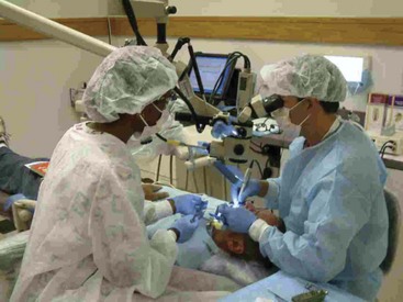
FIG. 7-3 The dental operating microscope (DOM) has vastly improved locating and negotiating of canal anatomy.
Components of the Root Canal System
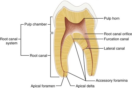
The entire space in the dentin where the pulp is housed is called the root canal system (Fig. 7-4). The outline of this system corresponds to the external contour of the tooth. However, factors such as physiologic aging, pathosis, and occlusion all potentially modify its dimensions through the production of secondary and tertiary dentin and cementum. The root canal system is divided into two portions: the pulp chamber, located in the anatomic crown of the tooth, and the pulp or root canal(s), found in the anatomic root. Other features are the pulp horns; accessory, lateral, and furcation canals; canal orifices; apical deltas; and apical foramina. A root canal begins as a funnel-shaped canal orifice, generally at or just apical to the cervical line, and ends at the apical foramen, which opens onto the root surface at or within 3 mm from the center of the root apex.30,80,81,163,215,220 Nearly all root canals are curved, particularly in a faciolingual direction. These curvatures may pose problems during shaping and cleaning procedures because they are not evident on a standard facial radiograph. Angled views are necessary to determine their presence, direction, and severity. A curvature may be a gradual curve of the entire canal or a sharp curvature near the apex. Double S-shaped canal curvatures also can occur. In most cases the number of root canals corresponds to the number of roots; however, an oval root may have more than one canal.
Accessory canals are minute canals that extend in a horizontal, vertical, or lateral direction from the pulp to the periodontium. In 74% of cases they are found in the apical third of the root, in 11% in the middle third, and in 15% in the cervical third.215 Accessory canals contain connective tissue and vessels but do not supply the pulp with sufficient circulation to form a collateral source of blood flow. They are formed by the entrapment of periodontal vessels in Hertwig’s epithelial root sheath during calcification.49 Pathologically, they are significant because they serve as avenues for the passage of irritants, primarily from the pulp to the periodontium (see also Chapter 18).
Accessory canals may also occur in the bifurcation or trifurcation of multirooted teeth.215 One study219 called these furcation canals (Fig. 7-5). Furcation canals form as a result of the entrapment of periodontal vessels during the fusion of the diaphragm, which becomes the pulp chamber floor.49 In mandibular molars these canals occur in three distinct patterns (Fig. 7-6). Tables 7-1 and 7-2 present the incidence of furcation canals for each tooth.

FIG. 7-5 Mandibular first molar showing a furcation canal (FC, arrows). F, Furcation; PC, pulp chamber floor; RC, root canal.
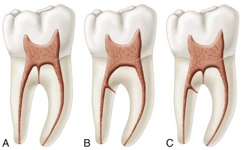
FIG. 7-6 Accessory canals occur in three distinct patterns in the mandibular first molars. A, In 13% a single furcation canal extends from the pulp chamber to the intraradicular region. B, In 23% a lateral canal extends from the coronal third of a major root canal to the furcation region (80% extend from the distal root canal). C, About 10% have both lateral and furcation canals.
According to the findings of scanning electron microscopy (SEM), the diameter of furcation openings in mandibular molars varies from 4 to 720 µm.216 The number of furcation canals ranges from none to more than 20 per specimen. Foramina on both the pulp chamber floor and the furcation surface were found in 36% of maxillary first molars, 12% of maxillary second molars, 32% of mandibular first molars, and 24% of mandibular second molars (Fig. 7-7). Mandibular teeth have a higher incidence of foramina involving both the pulp chamber floor and the furcation surface (56%) than do maxillary teeth (48%). No relationship was found between the incidence of accessory foramina and the occurrence of pulp chamber calcification or the distance from the chamber floor to the furcation. Radiographs failed to demonstrate the presence of furcation and lateral canals in the coronal portion of these roots. In one study, the pulp chamber floor of 200 permanent molars was stained with 0.5% basic fuscin dye.85 Patent furcation canals were detected in 24% of maxillary and mandibular first molars, 20% of mandibular second molars, and 16% of maxillary second molars. These canals may be the cause of primary endodontic lesions in the furcations of multirooted teeth (Fig. 7-8) and provide a rationale for placing adhesive restorations on the floor of the pulp chamber to prevent furcal breakdown.
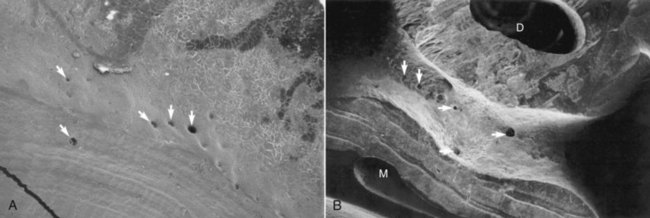
FIG. 7-7 A, Electron photomicrograph of the pulp chamber floor of a mandibular first molar. Multiple accessory foramina can be seen (arrows), ranging from 20 to 140 µm (×20). B, Electron photomicrograph of the furcation surface of a mandibular first molar. Multiple accessory foramina can be seen on the furcation surface (×30). D, Distal canal; M, mesial canals.
Root Canal Anatomy
Together with diagnosis and treatment planning, the knowledge of common root canal morphology and its frequent variations is a basic requirement for endodontic success. The significance of canal anatomy has been underscored by studies demonstrating that variations in canal geometry before shaping and cleaning had a greater effect on the changes that occurred during preparation than did the instrumentation techniques.160-162
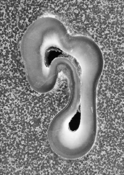
From the early work of Hess and Zurcher88 to more recent studies33,82,101,184 demonstrating the anatomic complexities of the root canal system, it has long been established that a root with a tapering canal and a single foramen is the exception rather than the rule. Investigators have shown multiple foramina, additional canals, fins, deltas, intercanal connections, loops, C-shaped canals, and furcation and lateral canals in most teeth.50,54,150,163,190,215 Consequently, in treating each tooth the clinician must assume that complex anatomy occurs often enough to be considered normal. The first premolar in Fig. 7-9, A is a good example of complex anatomy. The extra root is not obvious in a pretreatment radiograph (see Fig. 7-9, B). Figure 7-10 shows a cross-section of a similar tooth. This tooth has a fine, ribbon-shaped canal system instead of two distinct canals. Both these teeth present challenges for shaping, cleaning, and obturation.
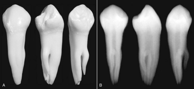
FIG. 7-9 A, Mandibular first premolar with three separate roots trifurcating at midroot. B, Radiograph of the three views. Small canals diverging from the main canal create a configuration that is difficult to prepare and obturate biomechanically.
The clinician must be familiar with the various pathways root canals take to the apex. The pulp canal system is complex, and canals may branch, divide, and rejoin. Weine232 categorized the root canal systems in any root into four basic types. Others,218 using cleared teeth in which the root canal systems had been stained with hematoxylin dye, found a much more complex canal system; they identified eight pulp space configurations, which can be briefly described as follows (Fig. 7-11):
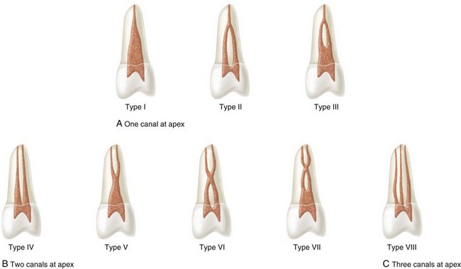
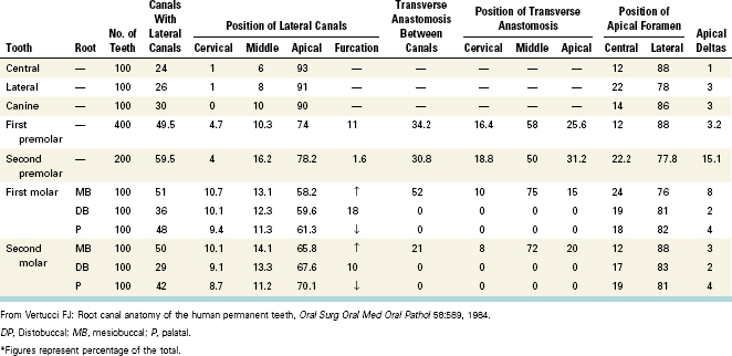
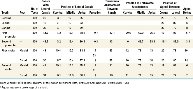
The percentages of human permanent teeth with these canal configurations are presented in Tables 7-3 and 7-4. The anatomic variations present in these teeth are listed in Tables 7-1 and 7-2. The only tooth that showed all eight possible configurations was the maxillary second premolar.
Other studies using more than 1000 teeth have described similar morphologic results.33 Another study used more than 1000 teeth and described similar morphologic results with the exceptions that one canal was found in 23% of maxillary laterals, 55% of mesiobuccal roots of maxillary second molars, and 30% of distal roots of mandibular second molars.33 The differences are most likely the result of variations of populations in the two studies.10 Another group studied 100 mandibular anterior teeth and found two new root canal types.101 In one configuration, two separate canals extended from the pulp chamber to midroot, where the lingual canal divided into two; all three canals joined in the apical third of the root and exited as one canal (Fig. 7-12, A). In the other configuration, one canal left the pulp chamber, divided into two in the middle third of the root, then rejoined to form one canal, which again split and exited as three separate canals with separate foramina (Fig. 7-12, B). Another set of variants was first observed in the mandibular molars of Burmese; this study revealed seven additional canal configurations (Fig. 7-13).82 These include three canals joining into one or two canals; two canals separating into three canals; two canals joining, redividing into two, and terminating as one canal; four canals joining into two; four canals extending from orifice to apex; and five canals joining into four at the apex. Another study evaluated gender-specific root canal configurations in 2800 teeth.184 Of these specimens 99% were identical to those in the Vertucci classification. The remaining 1% (36 teeth) represented 14 additional canal morphologies, which occurred twice as often in mandibular teeth. These authors concluded that gender plays a role in determining canal morphology and that both gender and ethnic origin should be considered in the pretreatment evaluation for root canal therapy.
FIG. 7-12 Diagrammatic representation of Kartal and Yanikoglu’s canal configurations. B, Buccal; L, labial.
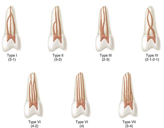
FIG. 7-13 Diagrammatic representation of Gulabivala and co-workers’ supplemental canal configurations.
In addition to in vitro studies, a large number of case reports have described a variety of complex canal configurations (see tables 7-8 to 7-27). Some authors have been critical of case studies reporting “freak” cases thought to be rare.231 However, reports of complex anatomy from both in vitro and in vivo investigations seem to be increasing. This emphasizes the adage that it is easier to recognize an anatomic feature if one is already prepared to see it.
Specific types of canal morphology appear to occur in different racial groups. For example, compared with Caucasian patients, those of African descent have a higher number of extra canals in both the mandibular first premolar (33% versus 14%) and the mandibular second premolar (8% versus 3%).211 In addition, patients of Asian descent have different percentages of canal configurations than those reported in studies dominated by white and black populations.223-225229 One well-recognized ethnic variant is the higher incidence of single-rooted and C-shaped mandibular second molars in Asians compared with other populations.127 However, this is not always the case; the occurrence of two canals in the mesiobuccal root of maxillary first molars in Japanese patients is similar to that described for other ethnic groups.233 All this information makes it clear that the clinician is confronted daily with highly complex and variable root canal systems. All available armamentaria must be used to achieve a successful outcome.
Examination of the pulp chamber floor can reveal clues to the location of orifices and to the type of canal system present. Importantly, if only one canal is present, it usually is located in the center of the access preparation. All such orifices, particularly if oval shaped, must be explored thoroughly with apically precurved small K-files (Fig. 7-14). If only one orifice is found and it is not in the center of the root, another orifice probably exists, and the clinician should search for it on the opposite side (Fig. 7-15). The relationship of the two orifices to each other is also significant. The closer they are, the greater the chance the two canals join at some point in the body of the root. As the distance between orifices in a root increases, the greater the chance is that the canals will remain separate. The more separation between orifices the less the degree of canal curvature.42 The direction a file takes when introduced into an orifice is also important. If the first file inserted into the distal canal of a mandibular molar points either to the buccal or to the lingual aspect, the clinician should suspect a second canal. If two canals are present, they will be smaller than a single canal.
FIG. 7-14 An oval orifice must be explored with apically curved small instruments. The clinician should place the file tip in the orifice with the tip curved to the buccal side when trying to locate the buccal canal. A curved file tip is placed toward the palate to explore for the palatal canal. B, Buccal; P, palatal.
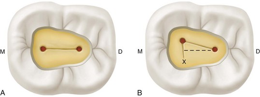
FIG. 7-15 A, In a mandibular second molar with two canals, both orifices are in the mesiodistal midline. B, If two orifices are not directly in the mesiodistal midline, a search should be made for another canal on the opposite side, using Krasner and Rankow’s laws of anatomy in the area of “X.” D, Distal; M, mesial.
Whenever a root contains two canals that join to form one, the lingual/palatal canal generally is the one with direct access to the apex. This anatomy is best treated by preparing and obturating this canal to the apex and the buccal canal to the point of juncture. If both canals are enlarged to the apex, an hourglass preparation results; the point where the two canals join is more constricted than the preparation at the apex. Filling such a configuration leaves voids in the apical third and invites treatment failure, particularly if microorganisms or their by-products remain in the canal. Rotary nickel–titanium files must be used cautiously with this type of anatomy because instrument separation can occur as the file traverses the sharp curvature into the common part of the canal. When one canal separates into two, the division is buccal and palatal/lingual, and the lingual canal generally splits from the main canal at a sharp angle, sometimes nearly a right angle (Fig. 7-16). One investigator191 recommends visualizing this configuration as a lower case letter h. The buccal canal is the straight-line portion of the h; the lingual canal exists about midroot at a sharp angle from the buccal canal. This requires modification of the access to achieve unobstructed passage of instruments into the lingual canal.
FIG. 7-16 A, Mesial view of a mandibular premolar with a Vertucci type V canal configuration. The lingual canal separates from the main canal at nearly a right angle. B, This anatomy requires widening of access in a lingual direction to achieve straight-line access to the lingual canal. This should be done with the dental operating microscope.
Anatomy of the Apical Root
The classic concept of apical root anatomy is based on three anatomic and histologic landmarks in the apical region of a root: the apical constriction (AC), the cementodentinal junction (CDJ), and the apical foramen (AF). Kuttler’s description of the anatomy of the root apex has the root canal tapering from the canal orifice to the AC, which generally is 0.5 to 1.5 mm coronal to the AF (Fig. 7-17).110 The AC generally is considered the part of the root canal with the smallest diameter; it also is the reference point clinicians use most often as the apical termination for shaping, cleaning, and obturation. Pulp blood vessels are narrow at the AC, which makes successful treatment of inflammation in the canal difficult. Posttreatment discomfort generally is greater when this area is violated by instruments or filling materials, and the healing process may be compromised.
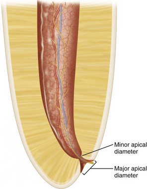
FIG. 7-17 Morphology of the root apex.
From its orifice the canal tapers to the apical constriction, or minor apical diameter, which generally is considered the narrowest part of the canal. From this point the canal widens as it exits the root at the apical foramen, or major apical diameter. The space between the minor and major apical diameters is funnel shaped.
The CDJ is the point in the canal where cementum meets dentin; it is the point where pulp tissue ends and periodontal tissues begin. The location of the CDJ in the root canal varies considerably. It generally is not in the same area as the AC, and estimates place it approximately 1 mm from the AF.178,193
From the AC, or minor apical diameter, the canal widens as it approaches the AF, or major apical diameter. The space between the major and minor diameters has been described as funnel shaped or hyperbolic, or as having the shape of a morning glory. The mean distance between the major and minor apical diameters is 0.5 mm in a young person and 0.67 mm in an older individual.110 The distance is greater in older individuals because of the buildup of cementum.
The AF is the “circumference or rounded edge, like a funnel or crater, that differentiates the termination of the cemental canal from the exterior surface of the root.”110 The diameter of the foramen is 502 µm in individuals 18 to 25 years of age and 681 µm in those over age 55, which demonstrates the growth of the AF with age.110 By comparison, these sizes are larger than the cross-sectional diameter of #50 and #60 endodontic files, respectively. The AF does not normally exit at the anatomic apex but rather is offset 0.5 to 3 mm. This variation is more marked in older teeth through cementum apposition. Studies have shown that the AF coincides with the apical root vertex in 17% to 46% of cases.*
The location and diameter of the CDJ differ from those of the AF in maxillary anterior teeth.167 The extension of cementum from the AF into the root canal differs considerably, even when opposite canal walls are compared. Cementum reaches the same level on all canal walls in only 5% of cases. The greatest extension generally occurs on the concave side of the canal curvature. This variability confirms that the CDJ and the AC generally are not in the same area and that the CDJ should be considered just a variable junction at which two histologic tissues meet in the root canal. The diameter of the canal at the CDJ varies considerably; it was determined to be 353 µm for the central incisors, 292 µm for the lateral incisors, and 298 µm for the canines.167 These measures approximate the size of #30 to #35 endodontic files.
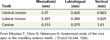
In maxillary anterior teeth, the root apex and main AF coincided in 17% of examined central incisors and canines and in 7% of lateral incisors.136 Both the root apex and the AF of the central incisors and canines were displaced distolabially, whereas those of the lateral incisors were displaced distolingually. The perpendicular distance from the root apex to the AC and both mesiodistal and labiolingual root canal diameters at the AC are shown in Table 7-5. The labiolingual diameter in all maxillary anterior teeth is approximately 50 µm more than the mesiodistal diameter. This has definite implications for shaping and cleaning procedures because only the mesiodistal diameter is evident on radiographs.
TABLE 7-5 Mean Perpendicular Distance From Root Apex to Apical Constriction With Mesiodistal and Labiolingual Diameters at Constriction
Scanning electron microscopy has been used to determine the number and size of main apical foramina, their distance from the anatomic apex, and the size of accessory foramina. In one study, more than one main foramen was found in all teeth except the palatal root of maxillary molars and the distal root of mandibular molars.142 No main foramen was seen in 24% of maxillary premolars and 26% of maxillary incisors. The mesial roots of mandibular molars (50%) and maxillary premolars (48%), and the mesial roots of maxillary molars (42%), had the highest percentage of multiple main foramina. This finding is consistent with observations that blunted roots usually have more than one root canal. The mean values for the size of the main foramen are listed in Table 7-6. Sizes ranged from 210 µm for the maxillary premolars to 392 µm for the distal roots of the mandibular molars.
TABLE 7-6 Size of Main Apical Foramina
| Teeth | Mean Value (µm) |
|---|---|
| Maxillary incisors | 289.4 |
| Mandibular incisors | 262.5 |
| Maxillary premolars | 210 |
| Mandibular premolars | 268.25 |
| Maxillary molars | |
| Palatal | 298 |
| Mesiobuccal | 235.05 |
| Distobuccal | 232.2 |
| Mandibular molars | |
| Mesial | 257.5 |
| Distal | 392 |
From Morfis A, Sylaras SN, Georgopoulou M, Kernani M, Prountzos F: Study of the apices of human permanent teeth with the use of a scanning electron microscope, Oral Surg Oral Med Oral Pathol 77:172, 1994.
All groups of teeth had at least one accessory foramen. The maxillary premolars had the most and the largest accessory foramina (mean value, 53 µm) and the most complicated apical morphologic makeup. The mandibular premolars had strikingly similar characteristics, a possible reason why root canal therapy may fail in premolar teeth.
The morphology of the apical root varies tremendously; it includes numerous accessory canals; areas of resorption and repaired resorption; attached, embedded, and free pulp stones; and varying amounts of irregular secondary dentin.137,138 Primary dentinal tubules are found less often than in the coronal dentin and are more or less irregular in direction and density. Some areas are completely devoid of tubules. Fine tubular branches (300 to 700 µm in diameter) that run at a 45-degree angle to the main tubules and microbranches (25 to 200 µm in diameter) that run at a 90-degree angle to the main tubules are often present (Fig. 7-18). This variable structure in the apical region presents challenges for root canal therapy. Obturation techniques that rely on the penetration of adhesives into dentinal tubules may not provide successful sealing in the apical region. Therefore the formation of a hybrid layer may become an important part of adhesive systems used in the apical root canal. Conversely, the reduction in dentinal tubules in this apical region leads to reduced chances of bacterial invasion into the dentinal walls of the root.

FIG. 7-18 Fine tubules and microbranches can be seen in the apical part of the root.
(From Mjör IA, Nordahl I: Arch Oral Biol 41:401, 1996.)
Considerable controversy exists over the exact termination point for root canal therapy.187 Clinical determination of apical canal morphology is difficult at best. The existence of an AC may be more conceptual than real. Several studies have reported that a traditional single AC was present less than half the time, particularly when apical root resorption and periradicular pathosis were factors.47,57,186,232 The apical root canal often is tapered, or walls are parallel to each other, or the canal has multiple constrictions. Some authors therefore have recommended the following termination points: 1 mm from the apex when no bone or root resorption has occurred; 1.5 mm from the apex when only bone resorption has occurred; and 2 mm from the apex when both bone and root resorption have occurred.232
Because locating the AC and AF is difficult clinically, some researchers contend that the radiographic apex is a more reliable reference point.246 These authors recommend that root canal procedures terminate at or within 3 mm from the radiographic apex, depending on the pulpal diagnosis. For vital cases, clinical and biologic evidence indicates that a favorable point at which to terminate therapy is 2 to 3 mm short of the radiographic apex.104,189 This leaves an apical pulp stump, which prevents extrusion of irritating filling materials into the periradicular tissues. With pulp necrosis, bacteria and their by-products may be present in the apical root canal, which could jeopardize healing. Studies have shown that, in these cases, a better success rate is achieved when therapy ends at or within 2 mm of the radiographic apex.103,104,189 When therapy ended short of the 2-mm point or extended past the radiographic apex, the success rate declined by 20%. For retreatment cases, therapy should extend to or preferably 1 to 2 mm short of the radiographic apex to prevent overextension of instruments and filling materials into the periradicular tissues.
Other investigators who evaluated apical and periradicular tissues after root canal therapy concluded that the most favorable prognosis was obtained when procedures were terminated at the AC, and the worst prognosis was produced by treatment that extended beyond the AC.112-115172 Procedures terminated more than 2 mm from the AC had the second worst prognosis. These findings occurred with vital and necrotic tissue and when bacteria were present beyond the AF. Sealer or gutta-percha (or both) in the periradicular tissues, lateral canals, and apical ramifications may cause a severe inflammatory reaction. However, the authors of the studies acknowledge the difficulty of locating the AC clinically. Some researchers recommend that clinicians terminate all therapy at or beyond the radiographic apex and fill all apical ramifications and lateral canals.180
The apical limit of instrumentation and obturation continues to be the subject of major controversy in root canal therapy. However, modern electronic apex locators are reliable instruments that can help the clinician determine the working length of the root canal.
Two hallmarks of the apical region are its variability and unpredictability. The tremendous variation in canal shapes and diameters complicates cleaning and shaping procedures in all dimensions. Successful treatment depends on the anatomy of the root canal system, the dimensions of the canal walls, and the final size of enlarging instruments.
Sometimes the initial file chosen for exploring the canal anatomy and for binding in the canal is used as a measure of the diameter of the apical root canal. However, this technique does not accurately gauge the size of oval-shaped apical root canals. In one study, file binding occurred in 75% of such cases when the file contacted only one side of the apical canal wall, and it occurred without any apical wall contact in the remaining 25%. In 90% of the canals, the diameter of the initial instrument was smaller than the short diameter of the canal.243 Consequently, using the first file to bind for gauging the diameter of the apical canal and as guidance for apical enlargement is not reliable. More recent studies have suggested that this problem could be remedied by removing the interferences in the coronal and middle thirds of the canal.45,116 For example, radicular flaring before canal exploration removes interferences and increases the initial file size that is snug at the apex (almost two file sizes greater).45 Early flaring gives the clinician a better sense of the size of the apical canal, allowing better decisions about the final diameter needed for apical shaping and cleaning. This is another advantage of the crown-down instrumentation technique.
The correlations between maximal canal diameters and instrument diameters varied considerably in a study that compared the shape of the apical root canal of maxillary first molars with the D0 diameter of endodontic instruments.71 Evaluation of the root canal diameter showed that a circular shape (the two diameters were equal) predominated in the palatal and MB-2 canals; a flat shape (the larger diameter exceeded the smaller by more than the radius) occurred most often in the main mesiobuccal (MB-1) canal; and both circular and flat shapes were found in the distobuccal canal. Flat and ribbon-shaped canals persisted near the apex even in elderly patients and mainly in the MB-1 canal. This finding was believed to arise from concentric narrowing of ribbon-shaped canals, primarily along the smaller diameter. Oval canals narrowed mainly along the larger diameter and tended to become more circular. The authors of this study concluded that the maxillary first molar has a very complicated canal shape at the apical limit and that this anatomy makes shaping, cleaning, and obturation difficult, particularly in the MB-1 and distobuccal canals. Because of this variability, guidelines for instrument calibers that would guarantee adequate canal preparation are virtually impossible to establish.
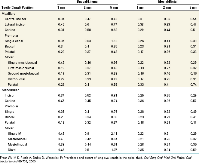
One comprehensive study reviewed the apical root canal diameters and tapers of each tooth group and demonstrated that root canals often are long and oval or ribbon shaped in the apical 5 mm (Table 7-7).244 A long oval canal was defined as having a ratio of the diameters of the long-to-short canal axes greater than 2. This type of canal morphology was found to occur in 25% of the cross-sections studied. In these roots the buccal/lingual diameter is greater than the mesial/distal diameter. This finding held true for all canals except the palatal canal of maxillary molars. These canal measurements suggest that apical preparations should be taken to larger sizes than previously recommended.
The authors of another study concluded that “because of long oval canals, larger canal tapers in the buccal–lingual direction, wider ranges in the apical diameters of canals, and the lack of technology to measure these diameters, it is very difficult if not impossible to adequately debride all canals by instrumentation alone.”210 This fact was further emphasized by research that showed that neither the balanced force instrumentation method nor rotary nickel–titanium files allowed controlled preparation of the buccal and lingual extensions of oval canals.174,245 The instruments created a round bulge in the canal, leaving the extensions unprepared and filled with smear layer and debris. Another series of studies evaluated the effectiveness of five nickel–titanium rotary instrumentation systems on canal debridement and found that all techniques left 35% or more of the canal surface area unchanged.160,162
The results of all these studies are fairly predictable, considering the highly variable and irregular morphology of root canal systems and the endodontic intracanal instruments currently in use, which cannot contact all the recesses present along canal walls. These instruments do a good job of shaping the canal but a poor job of accomplishing total canal debridement.
In an attempt to find better ways to clean and disinfect root canals, one group of investigators determined that enlarging canals to greater than the traditionally recommended apical sizes was the only way to remove culturable bacteria from the canal effectively.35 The larger apical sizes optimized irrigation and disinfection and facilitated mechanical elimination of microbes. A similar study concluded that an increase in the size of canal instrumentation at working length produced an increase in canal cleanliness.214 Irrigant volume, the number of instrument changes, and the depth of penetration of irrigant needles were less important factors contributing to canal debridement. A potential adverse effect of enlarging the apical canal diameter may be an increased risk of procedural errors or root fractures or both. Further research in this area is required.1
As a supplement to these procedures, acoustic streaming by sonic and ultrasonic irrigation appears to enhance the cleanliness of oval canals (Fig. 7-19).98,121 However, further research must be done to determine the best combination of treatment techniques to effectively debride these highly variable root canal systems.
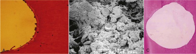
FIG. 7-19 A, Cross-section of a mandibular anterior tooth showing pulp remnants in the recesses of root canal walls in the apical 1 mm after preparation with a rotary nickel–titanium bur (size 40, #.08 taper) and manual irrigation (6% NaOCl and RC-Prep). B, Electron photomicrograph of the canal wall in A, showing canal wall debris (×3000). C, Cross-section of the mandibular anterior tooth showing clean canal walls in the apical 1 mm after preparation with a rotary nickel–titanium bur (size 40, #.08 taper) and sonic acoustic irrigation with 6% NaOCl.
One study used high-resolution computerized tomography to create a detailed, 3-D model of the root canal system.161 This method permits precise measurement of canal volume, area, and dimensions. The mean canal diameters in the apical 0.5 mm of maxillary molars were measured for the MB-1 canal (188 ± 5 µm), the distobuccal canal (174 ± 12 µm), and the palatal canal (318 ± 23 µm). Such information goes a long way toward the establishment of final instrumentation sizes for cleaning and shaping.
The apical anatomy studies also indicate that the root apex should be resected 2 to 3 mm during surgical procedures; this removes most of the unprepared and unfilled accessory canals, eliminating a potential reservoir of pathogens.90,142 In one study, researchers used a bevel perpendicular to the long axis of the root, and apical ramifications and accessory canals increasingly were eliminated by 1 mm of root resection (52% and 40%, respectively), 2 mm of root resection (78% and 40%), and 3 mm of root resection (98% and 93%).106 This showed that root-end resections of 3 mm are most effective for eliminating most of these structures.
In root-end resections a bevel perpendicular to the long axis of a root exposes a small number of microtubules.137,138 However, a root resection with a 45-degree bevel exposes a significantly greater number of tubules, increasing the chance of leakage into and out of the root canal.208,217 To prevent this, root-end cavity preparations should extend coronally to the height of the bevel (Fig. 7-20).
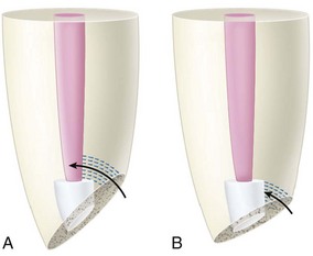
FIG. 7-20 Leakage through dentinal tubules originating at the beveled root surface. A, Reverse filling does not extend coronally to the height of the bevel. Arrows indicate a possible pathway for fluid penetration. B, Reverse filling extends coronally to the height of the bevel, blocking fluid penetration (arrows) into the root canal space.
(Redrawn from Vertucci FJ, Beatty RG: J Endod 12:335, 1986.)
The root apex contains a variety of anatomic structures and tissue remnants. Intercanal connections can become exposed, and a single foramen may become multiple foramina. Treatment results are poor if this altered anatomy is not recognized, prepared, and obturated. One study evaluated the root apex of teeth with refractory apical periodontitis that did not respond to root canal therapy and found that 70% had significant apical ramifications.222 This incidence strongly suggests a close relationship between the anatomic complexity of the root canal system and the persistence of periradicular pathosis.
An isthmus is a narrow, ribbon-shaped communication between two root canals that contains pulp or pulpally derived tissue. All isthmi must be found, prepared, and filled during surgery, because they can function as bacterial reservoirs. Any root with two or more canals may have an isthmus. Therefore the presence of an isthmus should be suspected whenever multiple canals are seen on a resected root surface. In one study, the authors recommended that methylene blue dye be used to aid visualization of the outline of the resected root surface and thus detection of an isthmus.34
In one study, isthmi in the mesiobuccal root of maxillary first molars were found most often 3 to 5 mm from the root apex.239 A complete or partial isthmus was found at the 4-mm level 100% of the time. In another study, partial isthmi were found more often than complete isthmi.204
Identification and treatment of isthmi are vital to the success of surgical procedures.34 Investigators 106 identified five types of isthmi that can be found on a beveled root surface (Fig. 7-21).
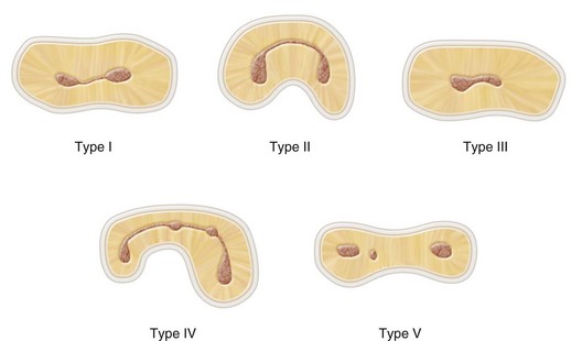
FIG. 7-21 Schematic representation of isthmus classifications described by Kim and colleagues.106 Type I is an incomplete isthmus; it is a faint communication between two canals. Type II is characterized by two canals with a definite connection between them (complete isthmus). Type III is a very short, complete isthmus between two canals. Type IV is a complete or incomplete isthmus between three or more canals. Type V is marked by two or three canal openings without visible connections.
Isthmi are found in 15% of anterior teeth; in maxillary premolar teeth, they are found in 16% at the 1-mm resection level and in 52% at the 6-mm resection level. The prevalence of isthmi increases in the mesiobuccal root of the maxillary first molar, from 30% to 50% as the root is resected from the 2- to 4-mm level. Eighty percent of the mesial roots of mandibular first molars have isthmi at the 3- to 4-mm resection level, whereas 15% of distal roots have isthmi at the 3-mm level. Microsurgical endodontic techniques have enabled clinicians to visualize the resected root surface and identify the isthmus, prepare it with ultrasonic tips, and fill the root-end preparation with acceptable materials. The recognition and microendodontic treatment of canal isthmi have significantly reduced the failure rate of endodontic surgery.174,175
Objectives and Guidelines for Access Cavity Preparation
Objectives
Access is the first and arguably most important phase of nonsurgical root canal treatment. A well-designed access preparation is essential for a good endodontic result.203 Without adequate access, instruments and materials become difficult to handle properly in the highly complex and variable root canal system. The objectives of access cavity preparation are (1) to remove all caries, (2) to conserve sound tooth structure, (3) to completely unroof the pulp chamber, (4) to remove all coronal pulp tissue (vital or necrotic), (5) to locate all root canal orifices, (6) to achieve straight- or direct-line access to the apical foramen or to the initial curvature of the canal, and (7) to establish restorative margins to minimize marginal leakage of the restored tooth.
A properly prepared access cavity creates a smooth, straight-line path to the canal system and ultimately to the apex, or position of the first curvature (Fig. 7-22). Straight line access provides the best chance of debridement of the entire canal space and reduces the risk of file breakage.140 When prepared correctly the access cavity allows complete irrigation, shaping and cleaning, and quality obturation. Ideal access results in straight entry into the canal orifice, with the line angles forming a funnel that drops smoothly into the canal(s). Projection of the canal center line to the occlusal surface of the tooth indicates the location of the line angles. Connection of the line angles creates the outline form. Modifications of the outline form may be needed to facilitate location of canals and to create a convenience form. The clinician must find a balance between creating adequate access and removing too much dentin, which could compromise the final restoration or promote crown fracture.

Guidelines
The guidelines described in the following sections are essential for the completion of an ideal access preparation.
Visualization of the Likely Internal Anatomy
Because internal anatomy dictates access shape, the first step in preparing an access cavity is visualization of the position of the pulp space in the tooth. This visualization requires evaluation of angled periapical radiographs and examination of tooth anatomy at the coronal, cervical, and root levels. Diagnostic radiographs help the clinician estimate the position of the pulp chamber, the degree of chamber calcification, the number of roots and canals, and the approximate canal length. Palpation along the attached gingiva aids the determination of root location and direction. The clinician uses the information from these assessments to choose the direction of initial bur penetration.
Evaluation of the Cementoenamel Junction and Occlusal Anatomies
Traditionally, access cavities have been prepared in relation to the occlusal anatomy. However, complete reliance on the occlusal anatomy is dangerous because this morphology can change as the crown is destroyed by caries and reconstructed with various restorative materials. Complete dependence on the occlusal anatomy may explain the occurrence of some procedural errors. In one a study involving 500 pulp chambers, Krasner and Rankow108 found that the cementoenamel junction (CEJ) was the most important anatomic landmark for determining the location of pulp chambers and root canal orifices. The study demonstrated the existence of a specific and consistent anatomy of the pulp chamber floor. These authors proposed nine guidelines, or laws, of pulp chamber anatomy to help clinicians determine the number and location of orifices on the chamber floor (Fig. 7-23).
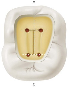
FIG. 7-23 Diagrammatic representation of Krasner and Rankow’s first and second laws of symmetry and first through third laws of orifice location. D, Distal; M, mesial.
More than 95% of the teeth these investigators examined conformed to these laws.108 Slightly fewer than 5% of mandibular second and third molars did not conform because of the occurrence of C-shaped anatomy.
Preparation of the Access Cavity Through the Lingual and Occlusal Surfaces
Access cavities on anterior teeth usually are prepared through the lingual tooth surface, and those on posterior teeth are prepared through the occlusal surface. These approaches are the best means of achieving straight-line access and diminishing esthetic and restorative concerns. Some authors have recommended that the traditional anterior access for mandibular incisors be moved from the lingual surface to the incisal surface in selected cases.132 This allows better access to the lingual canal and improves canal debridement (Fig. 7-24).
Removal of All Defective Restorations and Caries Before Entry Into the Pulp Chamber
The clinician must remove all defective restorations before entering the root canal system. With an open preparation, canals are much easier to locate, and shaping, cleaning, and obturation are much easier to perform. In one study,1 it was determined that clinicians were about 40% more likely to miss fractures, caries, and marginal breakdown if restorations were not completely removed. Working through restorations also allows restorative debris to become more easily lodged in the canal system (see Fig. 7-74, D).
All carious dentin must be removed during access preparation. This removal prevents irrigating solutions from leaking past the rubber dam into the mouth and prevents carious dentin and its bacteria from entering the root canal system. If a chamber wall is perforated during removal of carious dentin, allowing leakage of saliva into the pulp spaces, the wall must be repaired immediately with a temporary filling material, preferably from inside the cavity preparation. Sometimes removal of extensive defective restorations and carious dentin may not leave enough tooth structure for placement of a rubber dam clamp to seal against salivary contamination. A crown-lengthening procedure should be performed to correct this situation before the root canal procedure is begun.
Removal of Unsupported Tooth Structure
Preparation of an access cavity results in the removal of part of the central portion of the tooth thereby reducing the tooth’s resistance to occlusal stresses. After completing the preparation, the clinician should remove all unsupported tooth structure to assess restorability and to prevent tooth fracture. Unnecessary removal of sound tooth structure should be avoided.
Creation of Access Cavity Walls That Do Not Restrict Straight- or Direct-line Passage of Instruments to the Apical Foramen or Initial Canal Curvature
Complete clinician control over all enlarging and filling instruments is vital. Sufficient tooth structure must be removed to allow instruments to be placed easily into each canal orifice without interference from canal walls, particularly when a canal curves severely or leaves the chamber floor at an obtuse angle. Hence, access design is dependent not only on the orifice location, but also on the position and curvature of the entire canal. The walls of the root canal, rather than the walls of the access preparation, must guide the passage of instruments down the canal. Failure to follow this guideline results in treatment errors, including root perforation, misdirection of an instrument from the main canal (ledge formation), instrument separation, or creation of an incorrect canal shape (apical transportation). Following this guideline minimizes the occurrence of procedural errors and maximizes the effectiveness of shaping, cleaning, and obturation instruments.
Delay of Dental Dam Placement Until Difficult Canals Have Been Located and Confirmed
Difficulty can arise in gaining access into teeth that are crowded and rotated, fractured to the free gingival margin, heavily restored and calcified, or part of a fixed prosthesis. In these situations the clinician’s best course of action may be to prepare the initial part of the access cavity before placing the dental dam so that the inclination of root eminences can be visualized; this information can be used as an indicator of the direction of the long axis of the treated tooth. Micro-Openers (DENTSPLY Maillefer, Tulsa, OK) (Fig. 7-25) are excellent instruments for locating canal orifices when a dental dam has not been placed. These flexible, stainless steel hand instruments have #.04 and #.06 tapered tips. They also have offset handles that provide enhanced visualization of the pulp chamber.
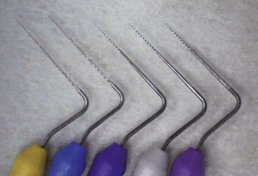
FIG. 7-25 Set of Micro-Openers (DENTSPLY Maillefer, Tulsa, OK) for canal identification and enlargement.
The dental dam must be placed once the roof of the pulp chamber has been penetrated and the canals identified.
Location, Flaring, and Exploration of All Root Canal Orifices
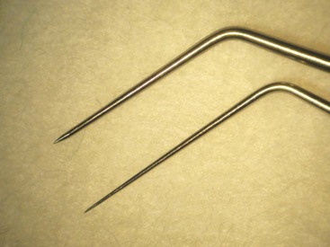
A sharp endodontic explorer is used to locate canal orifices and to determine their angle of departure from the pulp chamber. Next, all canal orifices and the coronal portion of the canals are flared to make instrument placement easier. The canals are then explored with small, precurved K-files (#6, #8, or #10). The clinician must take care to keep these instruments within the confines of the canal system until the working length has been accurately determined. A lubricating agent (e.g., RC-Prep [Premier Dental Products, Plymouth Meeting, PA], a water-based preparation that will not congeal vital pulp tissue), may be used on instruments and introduced into the canal. Congealed pulp tissue may form a collagen plug that blocks the apex, preventing complete shaping and cleaning.
Inspection of the Pulp Chamber, Using Magnification and Adequate Illumination
Magnification and illumination are particularly important in root canal therapy, especially for determining the location of canals; negotiating constricted, curved, and calcified canals; and débriding and removing tissue and calcifications from the pulp chamber. Enhanced vision allows the clinician to see internal dentin color changes and subtle landmarks that may not be visible to the unaided eye. Surgical loupes, endodontic endoscopes,12 and the DOM are some of the commercially available instruments that can help the clinician accomplish these goals. A clinician trained in microscopic techniques has a better chance of locating and negotiating intricate root canal systems.
Tapering of Cavity Walls and Evaluation of Space Adequacy for a Coronal Seal
A proper access cavity generally has tapering walls with its widest dimension at the occlusal surface. In such a preparation, occlusal forces do not push the temporary restoration into the cavity and disrupt the seal. At least 3.5 mm of temporary filling material (e.g., Cavit [3M, St. Paul, MN]) is needed to provide an adequate coronal seal for a short time.230 Recently, canal orifice plugs of composite, glass ionomer, and mineral trioxide aggregate (ProRoot MTA; DENTSPLY Tulsa Dental Specialties, Tulsa, OK) have shown promise in reducing the risk of bacterial contamination of the canal system when microleakage occurs at the coronal–restorative margins.96
Mechanical Phases of Access Cavity Preparation
Armamentaria
The preparation of an access cavity requires the following equipment:
Magnification and Illumination
The access cavity cannot be prepared adequately without the use of magnification and an appropriate light source. At the least, the clinician needs surgical loupes with an auxiliary light source (see Chapter 6). The DOM is the preferred means of magnification and illumination.
Handpieces
An experienced clinician with good tactile awareness is likely to perform most phases of access preparation with a high-speed handpiece. After penetration of the dentin, a less experienced clinician may benefit from the increased tactile awareness offered by a slow-speed handpiece. For challenging access cavity preparations, especially those involving calcified and receded pulp chambers, even experienced clinicians may sacrifice cutting speed and efficiency in favor of the increased cutting control of the slow-speed handpiece or an ultrasonic tip used with the DOM.
Burs
Numerous burs have been developed to assist the clinician with access cavity preparation. Providing a detailed, unabridged list of these burs would be difficult, and most clinicians have their own set of preferred access burs. In reality, creating an access cavity that meets the previously stated guidelines is more important than worrying about which burs are used in the process. This discussion therefore covers some of the more common access burs.
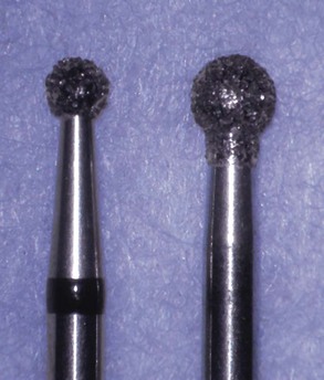
Round carbide burs (sizes #2, #4, and #6) (Fig. 7-26) are used extensively in the preparation of access cavities. They are used to remove caries and to create the initial external outline shape. They also are useful for penetrating through the roof of the pulp chamber and for removing the roof. Some clinicians prefer to use a fissure carbide bur (Fig. 7-27) or a diamond bur with a rounded cutting end (Fig. 7-28) to perform these procedures. The advantage of the fissure carbide and diamond round-end burs is that they also can be used for some of the axial wall extensions of the access cavity preparation. However, when these burs are used for this purpose by inexperienced clinicians, their cutting ends can gouge the pulp floor and axial walls (see Fig. 7-75, A).
Fissure carbide and diamond burs with safety tips (i.e., noncutting ends) (Fig. 7-29) are safer choices for axial wall extensions. They can be used to extend and favorably orient the axial walls of the pulp chamber. Because they have no cutting end, the burs can be allowed to extend to the pulp floor, and the entire axial wall can be moved and oriented all in one plane from the enamel surface to the pulp floor. Such a technique produces axial walls free of gouges as the final access extensions are created. Fissure carbide and diamond burs also can be used to level off cusp tips and incisal edges, which are used as reference points for the working length determination.
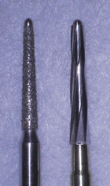
FIG. 7-29 Access burs: Safety-tip tapered diamond bur (left); safety-tip tapered carbide bur (right).
Round diamond burs (sizes #2 and #4) (Fig. 7-30) are needed when endodontic access must be made through porcelain or ceramometal restorations. Diamond burs are less traumatic to porcelain than carbide burs and are more likely to penetrate the porcelain without cracking or fracturing it. They should always be used with water spray to control heat buildup in porcelain restorations. After penetrating the porcelain the clinician should switch to a carbide bur for metal or dentin penetration because of this bur’s greater cutting efficiency.
A trend in restorative dentistry is the increased use of zirconia-based crowns and onlays. Zirconia has different mechanical and thermal characteristics than metal. Carbide burs do not cut zirconia efficiently or safely. Zirconia is a brittle material and, when cut, can develop cracks that propagate through the framework and lead to eventual failure of the crown or onlay. Diamond bur–manufacturing companies are aware of these issues and they are currently introducing medium- and fine-grit diamond burs that efficiently cut zirconia. These diamond burs should be used with copious water spray to minimize heat buildup in the zirconia crowns during access preparations. Also, some diamond burs degrade rapidly when cutting through zirconia and should be thrown away after one use.
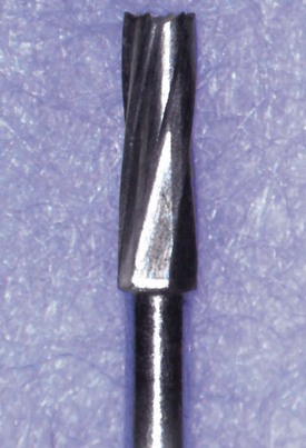
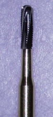
Many teeth requiring access cavity preparations have metal restorations that must be penetrated. These restorations may be amalgams, all-metal cast restorations, or metal copings of porcelain fused to metal crowns. A transmetal bur (Fig. 7-31) is excellent for this purpose because of its exceptional cutting efficiency. To penetrate a metal restoration, the clinician should always use a new transmetal bur with water spray for maximal cutting effect.
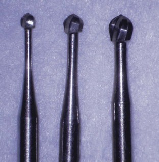
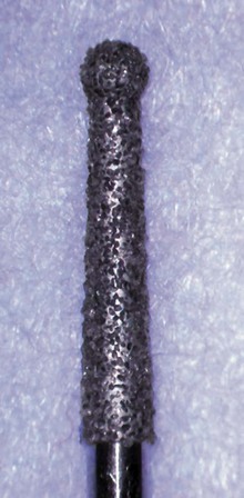
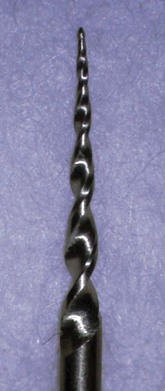
If a tooth has a receded pulp chamber and calcified orifices, the clinician often must cut into the root to locate and identify the canal orifices. Extended-shank round burs, such as the Mueller bur (Brasseler USA, Savannah, GA) (Fig. 7-32, A) and the LN bur (DENTSPLY Maillefer, Tulsa, OK) (Fig. 7-32, B), are useful for this purpose. The Munce Discovery bur (CJM Engineering, Santa Barbara, CA) is similar to the Mueller but has a stiffer shaft and is available in smaller head sizes. The extra-long shank of these burs moves the head of the handpiece away from the tooth, improving the clinician’s visibility during this delicate procedure. As an alternative, ultrasonic units offer good visibility with precision cutting.

Once the orifices have been located, they should be flared or enlarged and blended into the axial walls of the access cavity. This process permits the intracanal instruments used during shaping and cleaning to enter the canal(s) easily and effortlessly. Gates-Glidden burs can be used for this purpose, starting with smaller sizes and progressing to the larger sizes (Fig. 7-33). More recently, #.12 tapered rotary endodontic files (Fig. 7-34) have been used for the flaring and blending procedure. When using either of these two techniques for canal flaring, the clinician must guard against removing excessive dentin on the furcation side of a root canal, which could create a “strip” perforation.
Endodontic Explorer, Endodontic Spoon, #17 Operative Explorer
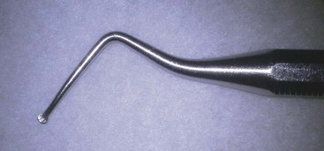
Various hand instruments are useful for preparing access cavities. The DG-16 endodontic explorer (Fig. 7-35) is used to identify canal orifices and to determine canal angulation. The JW-17 endodontic explorer (Fig. 7-35) (CK Dental Industries, Orange, CA) serves the same purpose, but its thinner, stiffer tip can be useful for identifying calcified canals. The endodontic spoon (Fig. 7-36) can be used to remove coronal pulp and carious dentin. A #17 operative explorer is useful for detecting any remaining pulp chamber roof, particularly in the area of a pulp horn (Fig. 7-37).
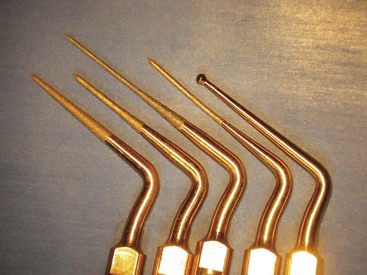
Ultrasonic Unit and Tips
An ultrasonic unit (Fig. 7-38) and tips specifically designed for endodontic procedures can be valuable aids in the preparation of access cavities. Ultrasonic tips (Fig. 7-39) can be used to trough and deepen developmental grooves to remove tissue and explore for canals. Ultrasonic systems provide outstanding visibility compared with conventional handpiece heads, which typically obstruct vision. Fine ultrasonic tips are smaller than conventional round burs, and their abrasive coatings allow clinicians to sand away dentin and calcifications conservatively when exploring for canal orifices.
Access Cavity Preparations
Anterior Access Cavity Preparations
Many of the same steps are used in similar tooth types to prepare an access cavity. The following discussion outlines the steps for maxillary and mandibular anterior teeth. Tooth-specific access concerns are illustrated and discussed in the section Morphology and Access Cavity Preparations for Individual Teeth, later in the chapter.
Removal of Caries and Permanent Restorations
Caries typically is removed early, before the pulp chamber is entered. This minimizes the risk of contamination of the pulp chamber or root canal(s) with bacteria. Defective permanent restorations, whether amalgams, composite resins, or crowns, must be removed entirely to prevent coronal leakage from contaminating the pulp chamber, the root canal(s), or both after the endodontic appointment. Removal of defective permanent restorations also permits straight-line access and prevents restorative fragments from becoming lodged in the root canal system (see Fig. 7-74, D). If recurrent decay is detected or suspected, the permanent restoration must be removed entirely to prevent coronal contamination of the pulp chamber.
The management of intact permanent restorations when recurrent caries is not present requires some judgment. Amalgam and composite restorations typically are removed entirely to improve visibility during the search for root canal orifices. As stated in an earlier study,1 clinicians were about 40% more likely to miss fractures, caries, and marginal breakdown if restorations were not completely removed. However, the clinician may want to retain the proximal portion of a class II restoration that extends subgingivally to aid in rubber dam isolation. When parts of existing permanent restorations are not removed, the clinician usually can widen the access opening larger than is ideal at the expense of removing restorative material, not sound tooth structure. The remaining permanent restoration material is removed at the end of the appointment before the temporary restoration is placed.
Often clinicians decide to perform endodontic therapy through intact crowns rather than removing or replacing them. These access cavities are repaired after completion of the root canal procedure. The patient and the clinician must realize that visibility can be compromised in these circumstances, particularly if a DOM is not used. The clinician can enhance visibility by beveling the crown’s cavosurface margins and by making sure all axial walls are glassy smooth.
Initial External Outline Form
Once caries and restorations have been addressed, the clinician creates an initial external outline opening on the lingual surface of the anterior tooth. This step often is performed during the removal of caries and restorations. For an intact tooth, the clinician should begin in the center of the lingual surface of the anatomic crown (Fig. 7-40, A). A #2 or #4 round bur or a tapered fissure bur is used to penetrate through the enamel and slightly into the dentin (approximately 1 mm). An outline form is created, similar in geometry to an ideal access shape for the particular anterior tooth (see Fig. 7-40, B); it is one half to three quarters the projected final size of the access cavity. Because most of this step involves removal of enamel, the high-speed handpiece is used for cutting efficiency. The bur is directed perpendicular to the lingual surface as the external outline opening is created (see Fig. 7-40, C).
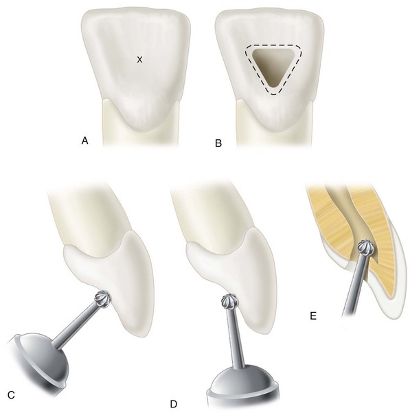
FIG. 7-40 A, In anterior teeth the starting location for the access cavity is the center of the anatomic crown on the lingual surface (X). B, Preliminary outline form for anterior teeth. The shape should mimic the expected final outline form, and the size should be one half to three fourths the size of the final outline form. C, The angle of penetration for the preliminary outline form is perpendicular to the lingual surface. D, The angle of penetration for initial entry into the pulp chamber is nearly parallel to the long axis of the root. E, Completion of removal of the pulp chamber roof; a round carbide bur is used to engage the pulp horn, cutting on a lingual withdrawal stroke.
Penetration of the Pulp Chamber Roof
Experienced clinicians can comfortably penetrate the pulp chamber roof with a high-speed handpiece, but less experienced clinicians may find the increased tactile sensation of a slow-speed handpiece a safer option. Continuing with the same round or tapered fissure bur, the clinician changes the angle of the bur from perpendicular to the lingual surface to parallel to the long axis of the root (see Fig. 7-40, D). Penetration into the tooth is accomplished along this root’s long axis until the roof of the pulp chamber is penetrated; frequently a drop-in effect is felt when this occurs. The clinician should measure the distance from the incisal edge to the roof of the pulp chamber on a dimensionally accurate pretreatment radiograph and limit penetration to this distance. If the drop-in effect is not felt at this depth, the clinician should evaluate the situation carefully to prevent a gouge or perforation. The depth and angle of penetration should be assessed for any deviation away from the long axis of the root in both the mesiodistal and buccolingual dimensions, and the penetration angle should be realigned if necessary. If all looks good, the clinician should probe the access opening with an endodontic explorer, using magnification and illumination. Often the sharp explorer tip penetrates through the pulp chamber roof with firm pressure. Angled radiographs should be taken to assess progress if any confusion or doubt exists. A little caution and concern at this stage can prevent an iatrogenic mishap (see Fig. 7-75, C).
Complete Roof Removal
Once the pulp chamber has been penetrated, the remaining roof is removed by catching the end of a round bur under the lip of the dentin roof and cutting on the bur’s withdrawal stroke (see Fig. 7-40, E). Because each tooth has a unique pulp chamber anatomy, working in this manner allows the internal pulp anatomy to dictate the external outline form of the access opening. In vital cases, pulp tissue hemorrhage can impair the clinician’s ability to see the internal anatomy. In such cases, as soon as enough roof has been removed to allow instrument access, the coronal pulp should be amputated at the orifice level with an endodontic spoon or round bur and the chamber irrigated copiously with sodium hypochlorite. If the hemorrhage continues, a tentative canal length can be established by measuring the pretreatment radiograph. A small broach coated with a chelating agent then can be introduced into the canal and rotated, thereby amputating the radicular pulp at a more apical level. This procedure is followed by irrigation with sodium hypochlorite. After hemorrhage has been controlled, allowing visibility, all of the pulp chamber roof, including the pulp horns, must be removed and all internal walls must be flared to the lingual surface of the tooth. Complete roof removal is confirmed with a #17 operative explorer if no “catches” are discovered as the explorer tip is withdrawn from the pulp chamber along the mesial, distal, and facial walls.
Identification of all Canal Orifices
After the pulp chamber has been unroofed, the canal orifices are located with an endodontic explorer (Fig. 7-41). This instrument is to the endodontist what a periodontal probe is to the periodontist. Used for reaching, feeling, and often digging at the hard tissue, it is the tactile extension of the clinician’s fingers. Natural anatomy indicates the usual places for orifices, but restorations, dentinal protrusions, and dystrophic calcifications can dictate the actual configuration the clinician encounters. While probing the chamber floor, the explorer often penetrates or dislodges calcific deposits blocking an orifice. It also can be used to evaluate straight-line access. Positioning the explorer in an orifice allows the clinician to check the shaft for clearance from the axial walls and to determine the angle at which a canal departs the main chamber (Fig. 7-42).
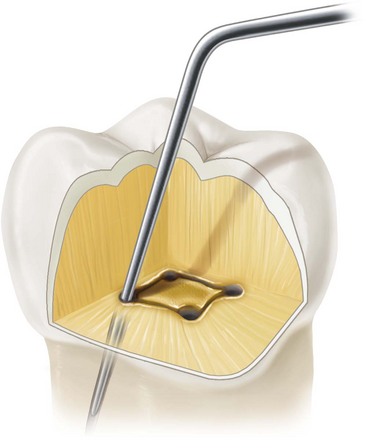
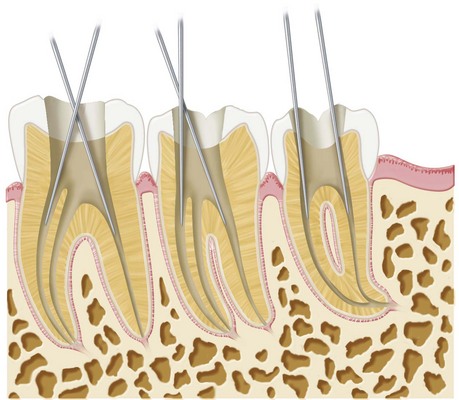
FIG. 7-42 Root canal orifices are explored to assess straight-line access and to determine the path of insertion for endodontic instruments.
The endodontic explorer is preferred over the rotating bur as the instrument for locating canal orifices. Not only is the explorer a safer option, its double-ended design also offers two angles of approach. The clinician should keep in mind the probability of finding additional canals in the tooth and the most likely anatomic location of these canals.
In a study94 involving maxillary molars, the authors looked at several pretreatment variables and their influence on the clinician’s likelihood of detecting root canals. The results of this study indicated that the number of root canals detected varied according to age and caries. Age was a significant factor in detecting fewer canals, most likely due to the calcification and morphologic changes that occurs in root canals as a patient ages. The presence of caries at the time of treatment resulted in the detection of greater number of root canals. However, because caries was associated with younger individuals in this study, age seems to play the dominant role in the clinician’s likelihood of detecting root canals.
Removal of the Lingual Shoulder and Orifice and Coronal Flaring
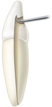
Once the orifice(s) has been identified and confirmed, the lingual shoulder is removed. This structure is the lingual shelf of dentin that extends from the cingulum to a point approximately 2 mm apical to the orifice (Fig. 7-43). Its removal aids straight-line access and allows for more intimate contact of files with the canal’s walls for effective shaping and cleaning.
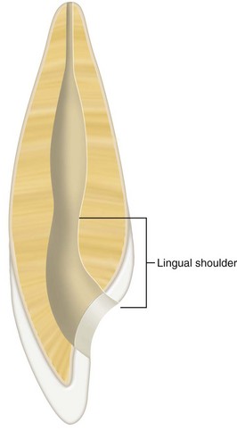
FIG. 7-43 Lingual shoulder of the anterior tooth, extending from the cingulum to 2 mm apical to the orifice.
The lingual shoulder can be removed with a tapered safety-tip diamond or carbide bur or with Gates-Glidden burs. The tip of a fine safety-tip diamond bur is placed approximately 2 mm apical to the canal orifice and inclined to the lingual during rotation to slope the lingual shoulder. The clinician must be careful when using this bur to avoid placing a bevel on the incisal edge of the access preparation (Fig. 7-44). When Gates-Glidden burs are used, the largest that can passively be placed 2 mm apical to the orifice is used first. During rotation, the bur is leaned against the lingual shoulder and withdrawn. The clinician can increase the size of these burs sequentially, depending on the size of the canal, and repeat the shaping of the lingual wall until the lingual shoulder of dentin has been eliminated.

FIG. 7-44 Placing an incisal bevel on the lingual surface of a maxillary anterior tooth can lead to fracture of the permanent restoration during occlusal function.
During this process the orifice should also be flared so that it is contiguous with all walls of the access preparation. This can be done with small to large Gates-Glidden burs. These burs are used in a circumferential filling motion, flaring each wall of the canal in sequence. To prevent iatrogenic mishaps on thin walls facing a root concavity, these burs should be placed passively into the canal and rotated as they are gently leaned against a canal wall and withdrawn.
Another approach to flaring the orifice involves the use of rotary nickel–titanium orifice openers; they should be used at slow speeds and low torque.
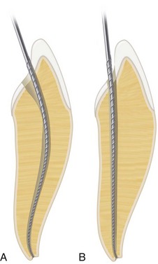
Straight-Line Access Determination
After the lingual shoulder has been removed and the orifice(s) flared, the clinician must determine whether straight-line access has been achieved. Ideally, an endodontic file can approach the apical foramen or the first point of canal curvature undeflected. Unnecessary deflection of the file can result in numerous consequences related to loss of instrument control. Deflected instruments function under more stress than undeflected instruments and are more susceptible to separation during the shaping and cleaning process (Fig. 7-45). Deflected instruments also lack access to critical areas of the canal and therefore do not shape and clean effectively. Attempts to shape and clean without straight-line access often lead to procedural errors such as ledging, transportation, and zipping (Fig. 7-46). A ledge is an iatrogenically created root canal wall irregularity that may impede placement of an intracanal instrument to the apex. Transportation occurs in the portion of the canal apical to a curvature when canal wall structure opposite the curve is removed, tending to straighten the canal curvature. Zipping, or elliptication of the apical foramen, occurs when an overextended file transports the outer wall of the apical foramen. Conversely, undeflected instruments provide better tactile sensation, which is necessary for “feeling” the canal anatomy and “feeling” how the file is performing in the root canal system.
FIG. 7-45 Separation of a rotary endodontic instrument as a result of underextended access preparation rather than canal binding.
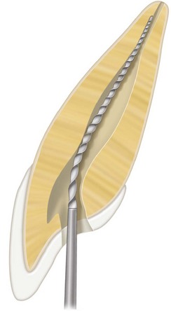
FIG. 7-46 Inadequate access preparation. The lingual shoulder was not removed, and incisal extension is incomplete. The file has begun to deviate from the canal in the apical region, creating a ledge.
Straight-line access is evaluated by inserting into the canal the largest file that fits passively to the apical foramen or the point of the first canal curvature. This internal length can be determined by measuring a diagnostic pretreatment periapical radiograph. The file is inserted gently and withdrawn as the clinician “feels” for canal binding or deflection. If deflection is detected, the clinician must reevaluate the adequacy of lingual shoulder removal before changing the incisal edge position of the access preparation. Inadequate removal of the lingual shoulder causes the file to deflect in a facial direction, and an inexperienced clinician may overextend the incisal edge of the access preparation in an attempt to achieve straight-line access (Fig. 7-47). If the lingual shoulder has been adequately removed and the file still binds on the incisal edge, the access cavity should be extended farther incisally until the file is not deflected. The final position of the incisal wall of the access cavity is determined by two factors: (1) complete removal of the pulp horns and (2) straight-line access.
Visual Inspection of the Access Cavity
The clinician should inspect and evaluate the access cavity, using appropriate magnification and illumination. Although this can be done during any stage of the preparation, it should always be done at this point. The axial walls at their junction with the orifice must be inspected for grooves that might indicate an additional canal. The orifice and coronal canal must be evaluated for a bifurcation (see Fig. 7-14).
Refinement and Smoothing of Restorative Margins
The final step in the preparation of an access cavity is to refine and smooth the cavosurface margins. Rough or irregular margins can contribute to coronal leakage through a permanent or temporary restoration. Proper restorative margins are important because anterior teeth may not require a crown as the final restoration. Definite, smooth cavosurface margins allow the clinician to place and finish a composite resin final restoration with the precision necessary to minimize coronal leakage. Such leakage could jeopardize the success of the root canal procedure.
Another factor the clinician must consider when finalizing the access margins of a maxillary anterior tooth is that the final composite resin restoration will be placed on a functional tooth surface. The incisal edges of the mandibular anterior teeth slide over these maxillary lingual surfaces during excursive jaw movement. Therefore the restorative margins of maxillary anterior teeth should be created to allow a bulk of restorative material at the margin. Butt joint margins are indicated rather than beveled margins, which produce thin composite edges that can fracture under excursive functional loads and ultimately result in coronal leakage. Obviously, if the anterior tooth requires a crown as the final restoration, the access cavosurface margin becomes a less critical factor.
Posterior Access Cavity Preparations
The process of preparing access cavities on posterior teeth is similar to that for anterior teeth, but enough differences exist to warrant a separate discussion.
Removal of Caries and Permanent Restorations
The discussion of caries and permanent restoration removal presented in the previous section, Anterior Access Cavity Preparations, applies equally to posterior teeth. Posterior teeth requiring root canal therapy typically have been heavily restored or the carious process is extensive. Such conditions, along with the complex pulp anatomy of posterior teeth, can make the access process challenging.
Initial External Outline Form
The removal of caries and existing restorations often accomplishes the creation of an initial external outline form. As with anterior teeth, the pulp chamber of posterior teeth is positioned in the center of the tooth at the level of the CEJ. An access starting location must be determined for an intact tooth. In maxillary premolars this point is on the central groove between the cusp tips (Fig. 7-48). Crowns of mandibular premolars are tilted lingually relative to their roots (Fig. 7-49), and the starting location must be adjusted to compensate for this tilt (Fig. 7-50). In mandibular first premolars the starting location is halfway up the lingual incline of the buccal cusp on a line connecting the cusp tips. Mandibular second premolars require less of an adjustment because they have less lingual inclination. The starting location for this tooth is one third the way up the lingual incline of the buccal cusp on a line connecting the buccal cusp tip and the lingual groove between the lingual cusps.
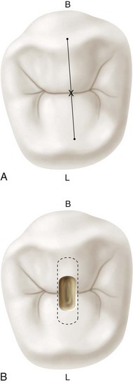
FIG. 7-48 A, Starting location for access to the maxillary premolar (X). B, Initial outline form (dark area) and projected final outline form (dashed line). B, Buccal; L, lingual.
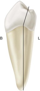
FIG. 7-49 The crown of a mandibular premolar is tilted lingually relative to the root. B, Buccal; L, lingual.
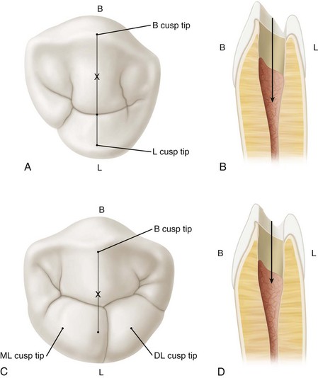
FIG. 7-50 A, Mandibular first premolar and access starting location (X) (occlusal view). B, Mandibular first premolar and starting location (proximal view). C, Mandibular second premolar and access starting location (X) (occlusal view). D, Mandibular second premolar and starting location (proximal view). B, Buccal; DL, distolingual; L, lingual; ML, mesiolingual.
To determine the starting location for molar access cavity preparations, the clinician must establish the mesial and distal boundary limitations (Fig. 7-51). Evaluation of bite-wing radiographs is an accurate method of assessing the mesiodistal extensions of the pulp chamber. The mesial boundary for both the maxillary and mandibular molars is a line connecting the mesial cusp tips. Rarely are pulp chambers found mesial to this imaginary line. A good initial distal boundary for maxillary molars is the oblique ridge. For mandibular molars the initial distal boundary is a line connecting the buccal and lingual grooves. For molars the correct starting location is on the central groove halfway between the mesial and distal boundaries.
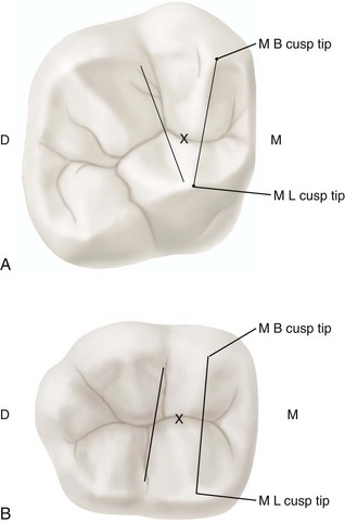
FIG. 7-51 A, Mesial and distal boundary of a maxillary molar showing the access starting location (X). B, Mesial and distal boundary of a mandibular molar showing the access starting location (X). D, Distal; M, mesial; MB, mesiobuccal; ML, mesiolingual.
Penetration through the enamel into the dentin (approximately 1 mm) is performed with a #2 round bur for premolars and a #4 round bur for molars. A tapered fissure bur may be used instead of round burs. The bur is directed perpendicular to the occlusal table, and an initial outline shape is created at about one half to three fourths its projected final size. The premolar shape is oval and widest in the buccolingual dimension. The molar shape is also oval initially; it is widest in a buccolingual dimension for maxillary molars and in a mesiodistal direction for mandibular molars. The final outline shape for molars is triangular (for three canals) or rhomboid (for four canals); however, the canal orifices dictate the position of the corners of these geometric shapes. Therefore, until the orifices have been located, the initial outline form should be left as an oval.
Penetration of the Pulp Chamber Roof
Continuing with the same round or tapered fissure bur, the clinician changes the angle of penetration from perpendicular to the occlusal table to an angle appropriate for penetration through the roof of the pulp chamber. In premolars the angle is parallel to the long axis of the root(s) both in the mesiodistal and buccolingual directions. Failure to analyze this penetration angle carefully can result in gouging or perforation because premolar roots often are tilted relative to the occlusal plane. In molars the penetration angle should be toward the largest canal, because the pulp chamber space usually is largest just occlusal to the orifice of this canal. Therefore, in maxillary molars the penetration angle is toward the palatal orifice, and in mandibular molars it is toward the distal orifice (Fig. 7-52).
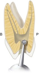
FIG. 7-52 Angle of penetration toward the largest canal (palatal) in a maxillary molar. B, Buccal; P, palatal.
As with anterior teeth, penetration is limited to the distance measured on a pretreatment radiograph to just penetrate the roof of the pulp chamber. If the drop-in effect is not felt at this depth, the clinician should carefully evaluate the angle of penetration before drilling deeper. In multirooted posterior teeth, the clinician must guard against lateral and furcation perforations. Aggressive probing with an endodontic explorer often can help locate the pulp chamber.
Complete Roof Removal
A round bur, a tapered fissure bur, or a safety-tip diamond or carbide bur is used to remove the roof of the pulp chamber completely, including all pulp horns (Fig. 7-53, A and B). Visibility problems caused by vital pulp hemorrhage should be handled as described in the previous section for anterior teeth (see Anterior Access Cavity Preparations). The goal is to funnel the corners of the access cavity directly into the orifices, and a safety-tip diamond or carbide bur performs this task nicely; it can be set on the pulp floor and the entire axial wall shaped at one time with little chance of gouging (Fig. 7-54). The safety-tip diamond or carbide bur is passed between the orifices along the axial walls to remove the roof, taper the internal walls, and create the desired external outline shape simultaneously.
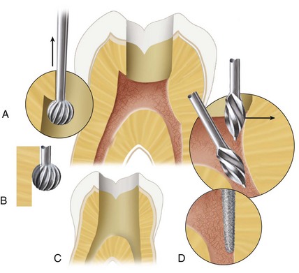
FIG. 7-53 A, Pulp roof/pulp horn removal. The round bur hooks under the lip of the pulp horn. B, The bur is rotated and withdrawn in an occlusal direction to remove the lip. C, Removal of a cervical dentin bulge. A Gates-Glidden bur is placed just apical to the orifice and withdrawn in a distoocclusal direction. D, A safety-tip tapered diamond bur is used to blend and funnel the axial wall from the cavosurface margin to the orifice.
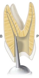
Identification of all Canal Orifices
In posterior teeth with multiple canals, the canal orifices play an important role in determining the final extensions of the external outline form of the access cavity. Ideally, the orifices are located at the corners of the final preparation to facilitate the shaping and cleaning process. Internally, the access cavity should have all orifices positioned entirely on the pulp floor and should not extend into an axial wall. Extension of an orifice into the axial wall creates a mouse hole effect (Fig. 7-55), which indicates internal underextension and impedes straight-line access. In such cases the orifice must be repositioned onto the pulp floor without interference from axial walls.
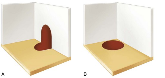
Removal of the Cervical Dentin Bulges and Orifice and Coronal Flaring
In anterior teeth the lingual shoulder is the internal anatomic structure that must be removed as an impediment to straight-line access. In posterior teeth the internal impediments are the cervical dentin bulges and the natural coronal canal constriction. The cervical bulges are shelves of dentin that frequently overhang orifices in posterior teeth, restricting access into root canals and accentuating existing canal curvatures. These bulges can be removed with safety-tip diamond or carbide burs or Gates-Glidden burs. The instruments should be placed at the orifice level and leaned toward the dentin bulge to remove the overhanging shelf (see Fig. 7-53, C and D).
After the shelf has been removed, the orifice and constricted coronal portion of the canal can be flared with Gates-Glidden burs, which are used in a sweeping upward motion with lateral pressure away from the furcation. An alternative method is to use a #.10 or #.12 tapered engine-driven nickel–titanium file to establish the upper canal shape. As the orifice is enlarged, it should be tapered and blended into the axial wall so that the clinician can slide from the corner of the external outline form down the axial wall into the orifice without encountering any obstructions (Fig. 7-56).
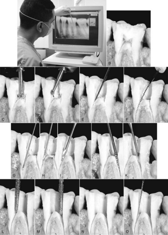
FIG. 7-56 A, Evaluation of the pretreatment radiograph. B, Clinical evaluation of the tooth. C, Penetration of the pulp roof. D, Removal of the pulp roof/pulp horns with a round carbide bur. E, Location of the orifice with a Mueller or LN bur. F, Exploration of the canal with a small K-file. G-I, Flaring of the orifice/coronal third of the mesial canal with Gates-Glidden burs. J, Flaring of the orifice/coronal third of the distal canal with a #.12 taper nickel–titanium rotary file. K, Flaring of the orifice/coronal third of the distal canal with a Gates-Glidden bur. L, Funneling of the mesial axial wall from the cavosurface margin to the mesial orifice. M, Funneling of the distal axial wall from the cavosurface margin to the distal orifice. N, Completed access preparation. O, Verification of straight-line access.
Straight-Line Access Determination
As with anterior teeth, straight-line access is paramount to successful shaping. Files must have unimpeded access to the apical foramen or the first point of canal curvature to perform properly during shaping and cleaning. The clinician must assess each canal for straight-line access and make all adjustments necessary to achieve this goal (see Fig. 7-56, O).
Visual Inspection of the Pulp Chamber Floor
Please refer to the earlier section under Anterior Access Cavity Preparations; and Fig. 7-57.
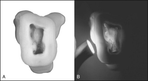
Refinement and Smoothing of the Restorative Margins
In both temporary and interim permanent restorations, the restorative margins should be refined and smoothed to minimize the potential for coronal leakage. The final permanent restoration of choice for posterior teeth that have undergone root canal therapy is a crown or onlay.
Challenging Access Preparations
Teeth With Minimal or No Clinical Crown
Several factors can cause the loss of a significant portion of a tooth’s clinical crown. Caries left untreated can cause loss of coronal tooth structure. Badly decayed teeth typically can fracture under occlusal function because of the undermined and unsupported remaining tooth structure. Similarly, teeth that have been heavily restored with amalgam, composite resin, or glass ionomer restorative materials can have minimal coronal tooth structure. These restorative materials provide no extracoronal support for the tooth, and the fillings can fall out during occlusal function, leaving little or no clinical crown remaining. External trauma can cause the clinical crown to fracture, sometimes shearing off to the free gingival margin.
Creating an access cavity on a tooth with little or no clinical crown might seem to be a simple procedure. In young teeth, traumatic fractures often expose the pulp chamber, making preparation easy. However, in older teeth that have had caries or large restorations, the pulp chambers typically have receded or calcified. Loss of significant coronal anatomy to guide penetration angles can make access quite difficult.
Before beginning an access cavity on these teeth, the clinician should study their root angulation on pretreatment radiographs and examine the cervical crown anatomy with an explorer (Fig. 7-58). Pulp chambers are located at the center of the crown at the level of the CEJ. Access often is started without a dental dam in place so that root eminences can be visualized and palpated as access is attempted (Fig. 7-59). Because the external root anatomy is formed by odontoblasts in the pulp, by visualizing the root anatomy both radiographically and clinically, the clinician should have a good idea of access penetration angles. Every effort is made to stay centered within the root for the best chance of locating the pulp canal.25 The depth of penetration needed to reach the pulp canal is measured on a pretreatment radiograph. If the clinician reaches this depth without locating the canal, two radiographs should be taken before the process proceeds. A straight-on radiograph shows whether the preparation is deviating in a mesial or distal direction. Applying the buccal-object rule, an angled radiograph shows a buccal or lingual deviation in penetration. After checking these radiographs, the clinician can redirect the penetration angle if necessary and move the preparation apically. As soon as the pulp canal is identified, the dental dam must be placed and the access preparation finalized, using the guidelines discussed earlier in this chapter.
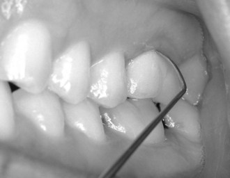
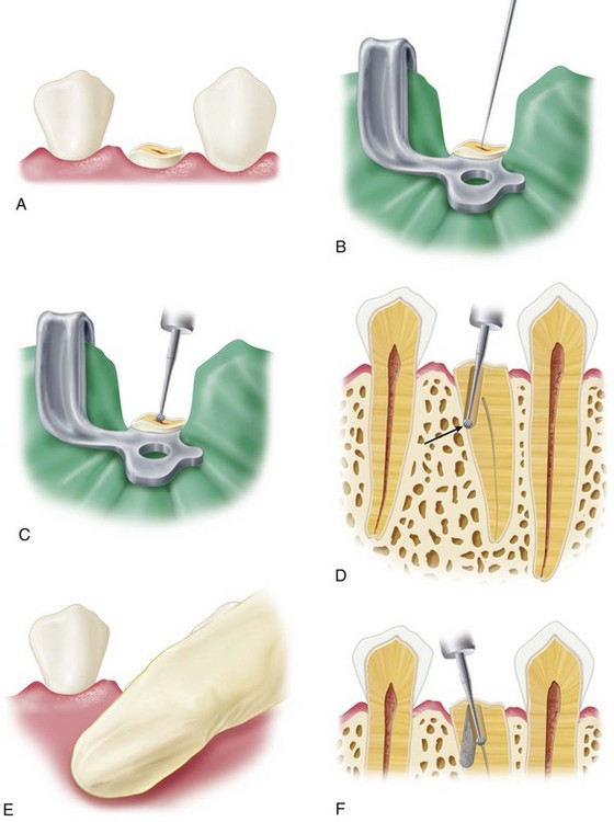
FIG. 7-59 Access cavity preparation when the anatomic crown is missing. A, A mandibular first premolar with the crown missing. B, An endodontic explorer fails to penetrate the calcified pulp chamber. C, A long-shank round bur is directed in the assumed long axis of the root. D, Perforation of the root wall (arrow), resulting from the clinician’s failure to consider root angulation. E, Palpation of the buccal root anatomy without a dental dam in place to determine root angulation. F, Correct bur angulation after repair of the perforation with mineral trioxide aggregate (MTA; DENTSPLY Tulsa Dental Specialties, Tulsa, OK). The dental dam is placed as soon as the canal is identified.
Heavily Restored Teeth (Including Those With Full Veneer Crowns)
Restorative materials often alter the external anatomic landmarks on the crown of a tooth, making access preparation difficult. Restorative materials and full crowns rarely reproduce the original tooth anatomy in the exact same position. The crown-to-root angulation often is altered when large restorations or crowns correct occlusal discrepancies (Fig. 7-60). Most restorative materials block the passage of light into the internal aspects of the tooth, resulting in poor visibility during preparation of the access cavity. All these factors, singly or together, complicate the preparation of access cavities on heavily restored teeth.1 The DOM and transillumination of the cervical area of a heavily restored tooth can greatly improve visibility and reveal landmarks that otherwise would be missed (see Fig. 7-57).
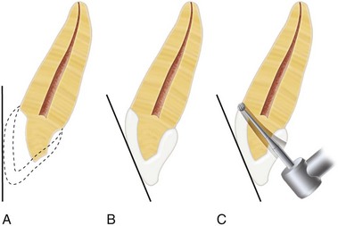
FIG. 7-60 Access cavity error resulting from alteration of the original tooth contours by a full veneer crown. A, Original crown contour of the tooth. B, A full veneer crown is used to change the original crown contour for esthetic purposes. C, Access perforation resulting from reliance on the full veneer crown contour rather than the long axis of the root.
In most cases, complete removal of large restorations is the wisest course (Fig. 7-61). These restorations often have leaky, defective margins or recurrent caries or both. Removing the restoration allows the clinician better visibility of the internal anatomic structures through direct visualization and increased light penetration. With increased visibility the clinician can check for recurrent caries and fracture lines on the pulp chamber walls or floor. As stated earlier in a study,1 clinicians are 40% more likely not to detect these anomalies when restorations are not removed completely. Better visibility also makes locating receded or calcified canals easier.

FIG. 7-61 A, In a heavily restored maxillary second molar that requires root canal therapy, the clinician may attempt access to the canals. Pretreatment radiographs demonstrate three important factors: (1) a reinforcing pin is in place (arrow); (2) at least two thirds of the coronal portion is restorative material; and (3) the mesiobuccal canal appears calcified (arrow). These factors suggest complete excavation. B, A patient may ask the clinician to attempt an unexcavated search for the canals; this may result in a furcal perforation, compromising the prognosis. In such cases the patient should be engaged in the decision to continue treatment, which unquestionably involves removal of the existing restoration. C, A safer, more conservative approach is to remove the amalgam, the pin, and any old cements. Careful excavation, using enhanced vision, results in access to the pulp chamber. D, The clinician now can perform sound root canal therapy, followed by internal reinforcement and full coverage.
Coronal leakage often occurs when parts of large restorations are left in the tooth because the restorations are loosened by the vibration of the access drilling. Another reason to remove these restoration remnants completely is to prevent pieces of the restorative material from falling into the root canal. Instruments can rub against restoration fragments during shaping and cleaning, creating filings that can be carried into the canal system (see Fig. 7-74, D). Complete removal prevents these problems.
Complete removal of an extensive restoration from the cervical region of the tooth permits more direct access to the root canal(s). For example, class V restorations often cause calcification of the coronal canal, making location of the canal through the occlusal approach quite difficult. Removal of the class V restoration allows more direct access to the calcified canal, which makes location and treatment much easier. Any remaining canals can be treated through the conventional occlusal access cavity (Fig. 7-62).
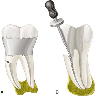
FIG. 7-62 A, Extensive class V restoration necessitated by root caries and periodontal disease that led to canal calcification (arrow). B, Access to the canal is occluded by calcification. Removal of the facial restoration may be required to obtain access from the buccal surface.
When an extensive restoration is a full or partial veneer crown, the restoration must be evaluated thoroughly. If any concerns arise about recurrent decay or leaky margins, the crown should be removed before the access cavity is prepared. Removal of the crown allows elimination of all recurrent caries and improves the visibility of the pulp spaces.
Creation of an access through an intact full or partial veneer crown should be done with caution. When such restorations are placed, they often change the crown-to-root angulation to correct preexisting occlusal discrepancies. Full veneer crowns also can alter tooth rotation. Both these situations make the preparation of access cavities challenging. Pretreatment radiographs can be helpful, but the metal in the full veneer crown often masks the underlying pulp chamber. In these situations the clinician’s best approach is to stay as centered in the tooth as possible, using all available clinical and radiographic information. The DOM and transillumination of the CEJ are valuable aides in this process.
Metal veneer crowns are best penetrated with new, sharp carbide burs. Round burs work well, but tungsten carbide transmetal burs are more efficient. These crosscut fissure burs are specifically designed to cut through metal restorative materials. Porcelain or ceramometal restorations must be handled delicately to minimize the potential for fracture. The clinician should use a round diamond bur and copious water spray to penetrate the porcelain. After porcelain penetration, a transmetal bur and copious water spray should be used to penetrate the metal coping; the water spray minimizes heat buildup, which could fracture the porcelain (Fig. 7-63).
FIG. 7-63 Access cavity preparation through a ceramometal crown. A, A round diamond bur is used to penetrate the porcelain. B, After the access outline has been made with the round diamond bur, a transmetal bur is used to cut through the metal. C, Prepared access cavity, which allows a direct approach to the canals. D, Test files can be placed on the access cavity walls without impingement.
Many clinicians tend to be too conservative when preparing an access cavity through a veneer crown. An attempt to save the crown often leads to an underextended preparation. All the guidelines for access cavity preparations discussed earlier must be followed. When the preparation is complete, the clinician should search the margins and internal spaces for caries, leakage, and fractures. If no problems are discovered, the clinician may proceed with shaping and cleaning, leaving the full veneer crown in place.
Teeth With Calcified Canals
A pretreatment radiograph (Figs. 7-64 and 7-65) often appears to reveal total or nearly total calcification of the pulp chamber and radicular canal spaces. Unfortunately, these spaces have adequate room to allow passage of millions of microorganisms. Chronic inflammatory processes (e.g., caries, medications, occlusal trauma, and aging) often cause narrowing of the root canal system. Canals become less calcified as they approach the root apex. Despite severe coronal calcifications, the clinician must assume that all canals exist and must be shaped, cleaned, and obturated to the canal terminus.
FIG. 7-64 Radiograph taken when a patient’s symptoms (i.e., nonlingering cold sensitivity and sensitivity to sweets) first appeared. The mandibular first molar was not treated endodontically because tests showed it to be vital. Caries was removed from under the mesial amalgam, and calcium hydroxide was placed over the cavity proximal to the pulp space.
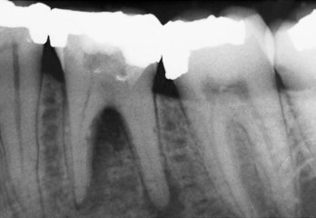
FIG. 7-65 Radiograph of the mandibular first molar in Fig. 7-64 taken 13 years later shows severe calcification of the pulp chamber and periradicular radiolucencies.
Teeth with severe pulp calcification may present problems with locating and negotiating root canals. The use of magnification and transillumination, as well as careful examination of color changes and pulp chamber shapes, can help the clinician safely locate canals. The clinician should search for root canal orifices only after completely preparing the pulp chamber and cleaning and drying its floor (95% denatured ethanol is useful for drying the floor and enhancing visibility). A fiberoptic light directed through the CEJ can reveal subtle landmarks and color changes that may not otherwise be visible. The chamber floor is darker in color than its walls, and developmental grooves connecting orifices are lighter in color than the chamber floor. The clinician must be aware of these color differences when searching for calcified orifices and must keep in mind that root canal orifices are located at the angles formed by the floor and walls and at the end points of developmental grooves. Additional aids for locating calcified root canals include staining the pulp chamber floor with 1% methylene blue dye, performing the sodium hypochlorite “champagne bubble” test (see Fig. 7-2) and searching for canal bleeding points.
In severely calcified teeth, calcified dentin must be removed slowly down the root. The clinician can use long, thin ultrasonic tips under the high magnification of a DOM to avoid removing too much tooth structure. As the search moves apically, two radiographs must be taken, one from the straight-on direction and the other from an angled direction. A very small piece of lead foil placed at the apical extent of the penetration can provide a radiographic reference.
Uncovering calcified canals is a challenge. When the canal is located, a small K-file (#6, #8, or #10) coated with a chelating agent should be introduced into the canal to determine patency. This file should not be removed until some canal enlargement has occurred. It should be used in short up-and-down movements and in a selective circumferential filing motion with most of the lateral pressure directed away from the furcation. This safely enlarges the coronal canal and moves it laterally to avoid the furcation. It also creates a path of insertion for larger files and for preflaring burs. Figures 7-64 through 7-71 illustrate several methods that can be used to locate calcified spaces. For the most successful results, the sequence should be followed as shown.
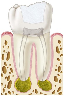
FIG. 7-66 Mandibular first molar with a class I restoration, calcified canals, and periradicular radiolucencies. Presumably pulp exposure has occurred, resulting in calcification and ultimately necrosis of the pulp tissue.
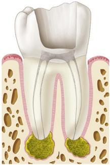
FIG. 7-67 Excavation of a restoration and base material. The clinician should extend the cavity preparation toward the assumed location of the pulp chamber, keeping in mind that pulp chambers are located in the center of the tooth at the level of the cementoenamel junction (CEJ).
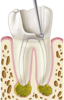
FIG. 7-68 The clinician uses a long-shank #2 or #4 round bur to remove dentin, attempting to locate calcified canals by following Krasner and Rankow’s anatomic laws.

FIG. 7-69 An endodontic explorer is used to probe the pulp floor. A straight ultrasonic tip may be used to remove dentin. Angled radiographs must be taken to monitor progress.
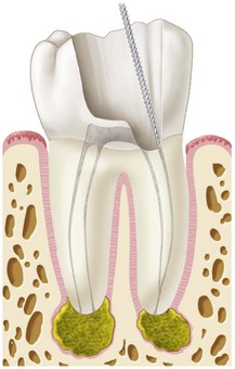
FIG. 7-70 At the first indication of a canal space, the smallest instrument (i.e., a #.06 or #.08 file) should be introduced into the canal. Gentle passive movement, both apical and rotational, often produces some penetration. A slight pull, signaling resistance, usually is an indication that the canal has been located. This should be confirmed by radiographs.
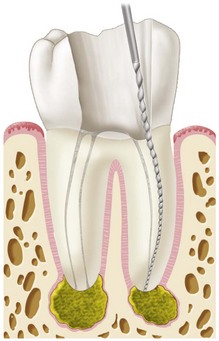
FIG. 7-71 A small hand K-file negotiates the canal to its terminus. An apex locator or radiograph is used to confirm the file’s position.
The wise clinician stops excavating dentin if a canal orifice cannot be found to avoid weakening the tooth structure. Serious errors can arise from overzealous or inappropriate attempts to locate canals. Root wall or furcation perforations can occur even with the most careful search. In such cases the communication with the periodontal tissues must be repaired immediately (Fig. 7-72). Retrograde surgical procedures may be a more conservative approach to treating the tooth when compared with perforations or root fractures. No rapid technique exists for dealing with calcified root canals. Painstaking removal of small amounts of dentin with the aid of the DOM and radiographic confirmation has proved to be the safest approach.
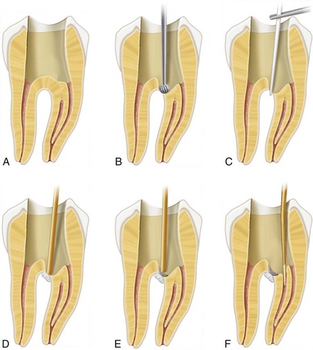
FIG. 7-72 Perforation repair. A, Access is gained into two canals, but the calcified canal orifice has not been located. B, Minute furcal perforation noted during the search for the canal. C, Absorbent points are used to control hemorrhage. D, CollaCote (Zimmer Dental, Carlsbad, CA) is introduced to provide a base for repair material. E, MTA (DENTSPLY Tulsa Dental, Tulsa, OK) is introduced. F, Location of the calcified canal; enhanced vision, including the dental operating microscope, is recommended.
Crowded Teeth
Conventional access preparations may not be possible in patients with crowded teeth. The decision regarding an alternative approach must be based on straight-line access principles and conservation of tooth structure. In certain circumstances a buccal access preparation may be the treatment of choice (Fig. 7-73). Modern restorative materials have made repair of this access esthetically acceptable.
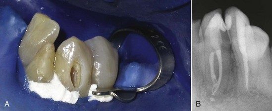
FIG. 7-73 A, Access cavity on crowded mandibular teeth. The access preparation is performed through the buccal surface on tooth #22. Tooth #23 also has been accessed through the buccal surface; root canal therapy was performed, and the access cavity was permanently restored with composite. B, Obturation.
Rotated Teeth
Rotated teeth can present problems for the clinician during access cavity preparation because of the altered crown-to-root relationships. According to one investigator,141 diagnostic periapical radiographs, although only two dimensional, are indispensable for “determining the anatomic relationship of the crown to the root and the angle of the root in the arch.” When these factors are identified, the clinician should visualize likely access variations before entering the tooth. Perforations in rotated teeth during access preparation usually occur because of faulty angulation of the bur with respect to the long axis of the root.
Other problems also can occur when tooth angulations are not considered during preparation of an access cavity. Such problems include the following:
The best way to handle these problems is to prevent them from occurring. A thorough radiographic examination is crucial. The initial outline form occasionally can be created without the dental dam; this facilitates positioning of the bur with the long axis of the tooth. Bur penetration for both depth and angulation should be confirmed frequently with radiographs.
Errors in Access Cavity Preparation
Unfortunately, errors can occur in the preparation of an access cavity. Most are the result of failure to follow the access guidelines; others reflect a lack of understanding of the internal and external tooth morphology. Common errors are discussed and illustrated in Figs. 7-74 through 7-76.