CHAPTER 9 Cleaning and Shaping of the Root Canal System
Framework for Root Canal Treatment
Clinical endodontics encompasses a number of treatments, but perhaps the most important is treating pulps and root canal systems (with or without periradicular pathosis of pulpal origin) so that patients can retain their natural teeth in function and esthetics. The treatment of traumatic dental injuries and prophylactic treatment of vital pulps to maintain vitality are different from pulpectomies in which root canal instrumentation is required. However, endodontic therapy essentially is directed toward one specific set of aims: to cure or prevent periradicular periodontitis.429
Routine orthograde root canal treatment is a predictable and usually highly successful procedure, both in relatively straightforward (Fig. 9-1) and more difficult cases (Figs. 9-2 and 9-3). In recent studies and reviews, favorable outcome rates of up to 95% were reported for the treatment of teeth diagnosed with irreversible pulpitis39,99,139; favorable outcome rates of up to 85% were reported for necrotic teeth.98,140,303,311
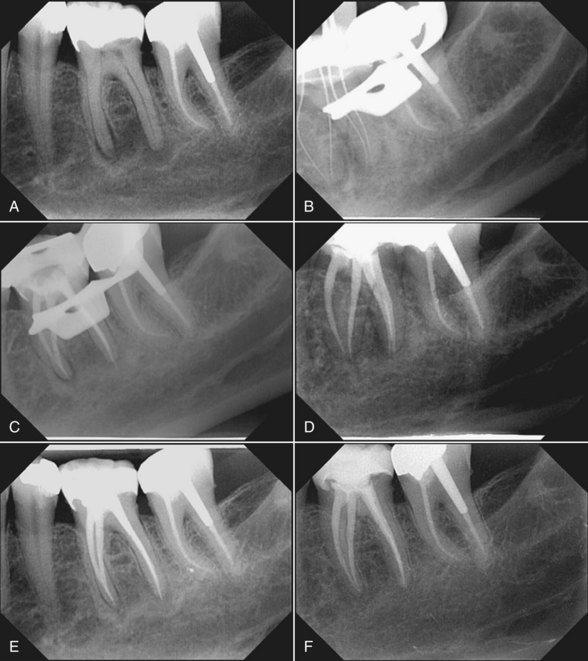
FIG. 9-1 Effect of routine root canal treatment of a mandibular molar. A, Pretreatment radiograph of tooth #19 shows radiolucent lesions adjacent to both mesial and distal root apices. B, Working length radiograph shows two separate root canals in the mesial root and two merging canals in the distal root. C, Posttreatment radiograph after shaping of root canal systems with nickel-titanium rotary files and obturation with thermoplasticized gutta-percha. D, Six-month recall radiograph after restoration of tooth #19 with an adhesively inserted full ceramic crown; some periradicular bone fill can be seen. E, One-year recall radiograph shows evidence of additional periradicular healing. F, Five-year recall radiograph; tooth not only is periapically sound but also clinically asymptomatic and fully functional.
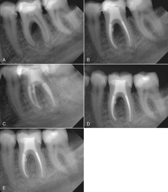
FIG. 9-2 Root canal treatment in a case of apical and interradicular pathosis. A, Pretreatment radiograph of tooth #19 shows an interradicular lesion. B-C, Posttreatment radiographs after root canal preparation and obturation. Note the lateral canal in the coronal third of the root canal. D-E, Two-month recall radiograph suggests rapid healing.
(Courtesy Dr. H. Walsch.)
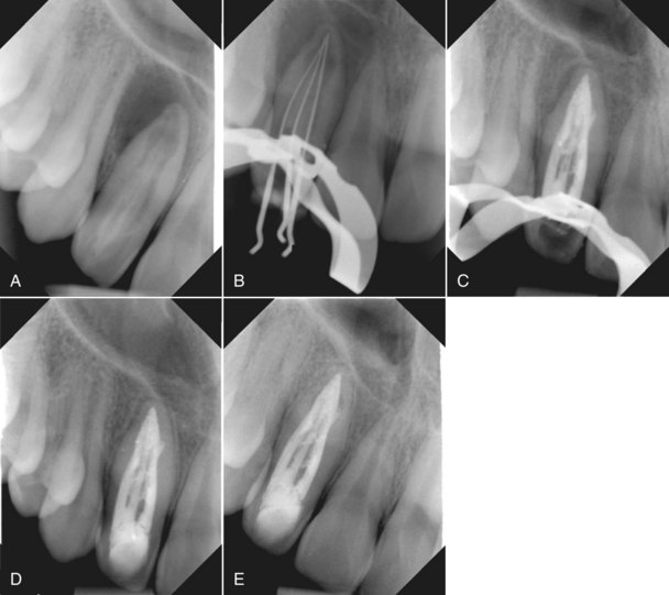
FIG. 9-3 Root canal treatment in a case with unusual and complicated anatomy. A, Pretreatment radiograph of tooth #7 in a 12-year-old boy shows a substantial periradicular lesion and evidence of additional radicular anatomy (i.e., a dens-in-dente type II, according to Oehlers’ classification).285 B, Working length radiograph shows three separate root canals. C, Posttreatment radiograph  months after shaping of the root canal systems with a nickel-titanium rotary system aided by ultrasonically activated K-files and dressing with calcium hydroxide four times for about 2 weeks each. Note the substantial periradicular bone fill. D, One-year recall radiograph shows evidence of periradicular healing. E, Two-year recall radiograph shows sound periradicular tissues.
To date, many treatment modalities, including nickel-titanium rotary instruments, have not been shown to have a statistically relevant impact on treatment outcomes.303 This poses a real problem in the age of evidence-based therapy, because a new therapeutic technique should provide a better result than standard procedures in clinical tests. The small number of relevant prospective clinical studies is only partly offset by numerous in vitro experiments. This chapter includes pertinent information from such studies, as well as results from our own experiments, because rotary nickel-titanium instruments have become widely used adjuncts in root canal treatment.
Pathophysiology of Endodontic Disease
Many prospective and peritreatment factors have been suggested as links to favorable treatment outcomes in endodontic therapy. Such factors include the patient’s age and gender, the position of the tooth in the arch, extension of the root canal filling, and the use of certain interappointment dressings, such as calcium hydroxide [Ca(OH)2]. The presence of a periradicular osseous lesion (i.e., “apical periodontitis”) appears to be a relevant prognostic factor that reduces the likelihood of a favorable outcome for root canal treatment; however, lesion size by itself is not an indication for endodontic surgery (see Chapter 22). Fig. 9-4 shows two cases in which large osseous lesions were treated by orthograde approaches. At recall appointments, the teeth were asymptomatic, and a reduction in lesion size was evident in both cases.
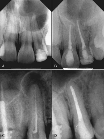
FIG. 9-4 Potential of root canal treatment in cases of substantial periradicular destruction. A, Pretreatment radiograph of teeth #8 and #9 shows a large lesion. Neither tooth responded to cold tests. B, Two-year follow-up radiograph shows bone fill. The canals were shaped with rotary and hand instruments, and obturation was performed using laterally compacted gutta-percha with AH Plus as the sealer. C, Pretreatment radiograph of tooth #4, which has a previously filled root canal; a large periradicular lesion and insufficient obturation can be seen. D, Two-year posttreatment radiograph shows evidence of bony healing after nonsurgical retreatment.
(A-B courtesy Dr. M. Zehnder; C-D courtesy Dr. F. Paqué.)
Some may question whether lesions such as the ones in Fig. 9-4 are in fact cysts. Several studies have demonstrated that lesion size shows little correlation with the incidence of radicular cysts.55,222,275,279 Only histologic examination can prove whether a radiolucency is in fact a cyst. True cysts are believed to heal only after surgical enucleation,278 whereas the noncystic majority of apical processes heal predictably by orthograde endodontic treatment without surgery. An orthograde approach, therefore, appears to be beneficial in clinically asymptomatic cases and should include recall appointments at appropriate intervals (see Chapter 14).
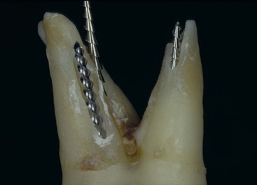
If clinical symptoms persist or begin after endodontic therapy, surgery may be performed in addition to orthograde root canal treatment. In the case shown in Fig. 9-5, a large lesion that extended into the maxillary sinus and nasal cavity was treated surgically 1 week after orthograde therapy of teeth #7 and #8, which included removal of two instrument fragments. The lesion was completely enucleated during surgery, and a tissue biopsy specimen was submitted for histologic processing; the lesion was diagnosed as a radicular cyst. As expected in this case, the patient reported discomfort after surgery. This supports the preference for a nonsurgical approach whenever possible.

FIG. 9-5 Possibilities and limitations of orthograde endodontic therapy. In this case, a large lesion in the right maxilla was enucleated and histologically diagnosed as a radicular cyst. A, Pretreatment occlusal plane radiograph shows a large periradicular lesion in the right maxilla, as well as two separated instruments in tooth #7 (arrow). B, Posttreatment periapical radiograph of tooth #7 and necrotic tooth #8, which were obturated after calcium hydroxide dressings had been placed for 2 weeks. Obturation was done with laterally compacted gutta-percha and Roth’s 801 sealer. C, Two lentulo spiral fragments removed from tooth #7 (ruler gradation is 0.5 mm). D, Histologic slide shows both respiratory epithelium (arrow) and squamous epithelial lining and inflammatory cells, supporting the diagnosis.
(C Courtesy Dr. I. Hegyi.)
When root canal therapy is part of a comprehensive treatment plan, a favorable outcome for the root canal portion is a prime requirement. Extended bridgework and removable dentures depend on healthy periradicular tissues, just as they depend on healthy marginal and apical periodontal tissues. Fig. 9-6 presents a case in which a removable denture seemed unavoidable at the first examination. After extractions and root canal therapy were performed, small-unit, fixed partial dentures were placed. These reconstructions remain fully functional and allow this patient to benefit from the natural dentition.
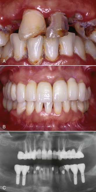
FIG. 9-6 Root canal therapy as part of a comprehensive treatment plan. The patient, who was recovering from intravenous drug addiction, requested restorative dental treatment. Because of extensive decay, several teeth had to be extracted, and nine teeth were treated endodontically. Root canal treatment was aided by nickel-titanium rotary instruments, and obturation was done with lateral compaction of gutta-percha and AH26 as the sealer. Microsurgical retrograde therapy was performed on tooth #8, and the distobuccal root of #14 had to be resected. Metal-free adhesively luted restorations were placed, and missing mandibular teeth were replaced by implants. A, Pretreatment intraoral status, showing oral neglect. B, Posttreatment intraoral status at 4-year follow-up, showing fully functional, metal-free, tooth-colored reconstructions. C, Panoramic radiograph at 4-year recall shows sound periradicular tissues in relation to endodontically treated teeth.
(Restorations done by Dr. Till N. Göhring.)
In summary, orthograde root canal treatment has a high degree of predictability both in normal and complex cases. Some limitations exist, but the potential for a favorable outcome is significant. As indicated previously, the shaping and cleaning procedures performed as part of root canal treatment are directed against microbial challenges to the root canal system.170 Microorganisms can breach dental hard-tissue barriers through several avenues, the most common being dental caries (Fig. 9-7).327
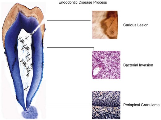
FIG. 9-7 Schematic representation of the progression of pulpal disease and the development of periradicular pathosis. A carious lesion leads to contact of toxins and microbes with the coronal pulp, resulting in inflammation and infection. The stereotypic defense reaction of dental pulp then occurs: hard-tissue deposition. This reaction may lead to repair or to additional hard-tissue deposition (e.g., as calcific metamorphosis). The next step may be formation of microabscesses, changes in circulation during inflammation, and ultimately progression of infection into the radicular pulp space. Finally, periradicular osseous lesions may develop if the bacterial challenge persists.
(Courtesy Professor H.-U. Luder and T. Häusler.)
Dental Anatomy
Pulpal reactions may be observed as soon as the diffusion barrier (the remaining dentin thickness) is sufficiently permeable for bacteria or their toxins to affect the pulp56 (see Fig. 9-7). Under experimental conditions, pulpal inflammation can be detected only a few hours after topical application of bacterial components to exposed dentin.46,286 In an established lesion, a bacterial ecosystem evolves, with synergisms and antagonisms among the microorganisms (see Chapter 15). These interactions play an important role in the course of the disease when intraradicular biofilms develop and bacteria invade dentinal tubules.236 Two key factors initiate and modify inflammatory reactions such as the development of microabscesses in subodontoblastic regions: the penetration of bacterial components and the release and diffusion of inflammatory mediators.
The stereotypic pulpal defense reaction is hard-tissue deposition (Fig. 9-8 and see Fig. 9-7) by primary and secondary odontoblasts.56 Hard tissue is laid down as a response to a stimulus (reactionary or reparative dentinogenesis) and thus takes place within a defined spatial relationship to that stimulus, occurring slightly apical to the lesion.
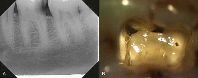
FIG. 9-8 Evidence of coronal hard-tissue deposition. A, Periapical radiograph of tooth #19 shows evidence of reduced coronal and radicular pulp space. B, Intraoral photograph, taken through an operating microscope (×25), of access cavity of the tooth shown in A; note the calcific metamorphosis.
Hard-tissue deposition is a natural event with aging451 (secondary dentinogenesis), which creates a higher degree of treatment difficulty in older patients.452 Clinicians note a radiographically detectable decrease in the size of the pulp space that occurs most often in the coronal regions but also can be seen in the more apical areas. This condition is not a contraindication to orthograde endodontic therapy, but it does require additional attention to clinical procedures such as preenlargement and prebending of hand files (discussed later in this chapter).
The process of calcific metamorphosis is a response to traumatic injury.22 It is characterized by a reduction in the size of both the radicular and coronal pulp spaces. Conversely, teeth with signs of hard-tissue deposition caused by bacterial attack show an initial reduction of pulp space size coronally, which may involve the pulp chamber and canal orifices (see Fig. 9-7). This situation calls for meticulous preparation of an access cavity and preenlargement of canal orifices in a nondestructive manner. Depending on the timing of inoculation and the number of microbes, hard-tissue deposition also may occur more apically.215
Reparative dentin may form a diffusion barrier sufficient for the pulp to recover, depending on the severity of the bacterial challenge and the capability of the defense mechanisms.242 Unfortunately, no consensus exists on the best therapy to allow this recovery to occur.47 Further into the disease progress, and if the carious lesion persists, bacteria may be present in sufficient concentrations to induce pulpal inflammation. This is triggered by molecular signals (e.g., cytokines) released from cells such as macrophages and neutrophils well before microbes are actually present intrapulpally (see Chapter 15). At this stage, with a diagnosis of reversible pulpitis, endodontic treatment may be avoidable, provided the source of the irritants is removed.
To deliver adequate endodontic therapy, the clinician must understand that apical periodontitis is the endpoint of a disease flow that in most cases originates coronally, either with carious lesions or a traumatized pulp (see Fig. 9-7). As stated previously, opportunistic bacteria may invade dental hard tissue, and their byproducts eventually may reach the pulp space (see Chapter 15). Host response factors, such as the recruitment of neutrophil granulocytes and local development of neurogenic inflammation, act against microbial invasion, but this line of defense may succumb to the challenge if the carious defect is not repaired. Then, after microabscesses form, circulation changes occur; coronal and subsequently radicular pulp may become nonperfused and thus necrotic.
At various points in this process, bacterial factors such as lipopolysaccharides and peptidoglycans201 can reach periapical tissues through apical and accessory foramina. Zones of bone resorption (appearing as radiolucencies) may develop, depending on the balance between microbial virulence factors and host defenses.402 The development of apical periodontitis is associated with a significantly less encouraging prognosis after orthograde endodontic treatment.99,387,389
One school of thought emphasizes the importance to successful endodontic therapy of cleaning and filling lateral and accessory canals.337,458 Clinical radiographs of beautifully performed cases support this position; the contribution of accessory canals to lesion development in certain cases seems highly likely (see Fig. 9-2). However, this pathogenesis depends on the volume of accessory canals and the amount of bacteria harbored in them. Another subject of controversy is the clinical importance and mechanisms of dentinal tubule infection235,236,300 with bacteria and fungi (Fig. 9-9).
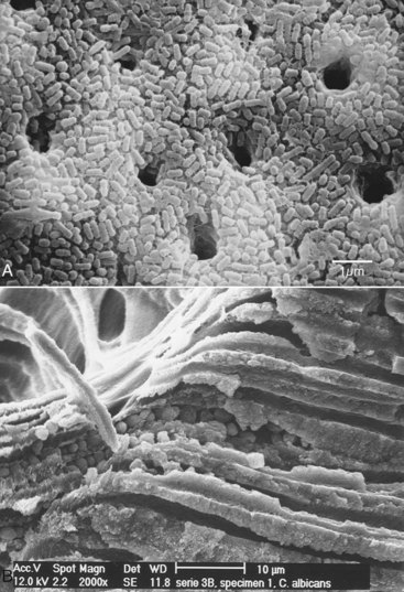
FIG. 9-9 Presence of microorganisms inside the main root canal and dentinal tubules. A, Scanning electron micrograph of a root canal surface shows a confluent layer of rod-shaped microbes (×3000). B, Scanning electron micrograph of a fractured root with a thick smear layer and fungi in the main root canal and dentinal tubules.
(A courtesy Professor C. Koçkapan; B courtesy Professor T. Waltimo.)
In most cases, lesions are associated with the main root canal systems (see Figs. 9-1 and 9-3 to 9-5) and form periapically around the main foramina. The main canal unquestionably has the highest bacterial load, and important studies link reduction of the viable intracanal bacterial load to favorable outcomes for endodontic therapy.207,299,387 A primary aim of all endodontic procedures, and most notably of cleaning and shaping, is to remove canal contents, specifically infective microorganisms and necrotic tissues.2
Clinical Objectives
A wide spectrum of possible strategies exists for attaining the goal of removing the canal contents and eliminating infection. Investigators244 introduced a minimally invasive approach to removing canal contents and accomplishing disinfection that did not involve the use of a file: the noninstrumentation technique.137 This system consisted of a pump, a hose, and a special valve that was cemented into the access cavity (Fig. 9-10, A) to provide oscillation of irrigation solutions (1% to 3% sodium hypochlorite3) at a reduced pressure. Although several in vitro studies243,245,246 demonstrated that canals can be cleaned and subsequently filled using this system (see Fig. 9-10, B and C), preliminary clinical results have not been as convincing (see Fig. 9-10, D).27
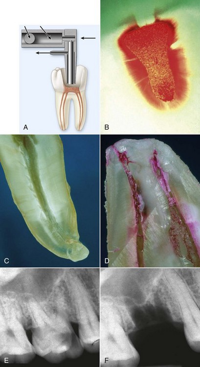
FIG. 9-10 Spectrum of strategies for accomplishing the primary aim of root canal treatment: elimination of infection. A, Schematic diagram of minimally invasive therapy using the noninstrumentation technique (NIT). B, Example of teeth cleaned in vitro using NIT. Note the clean intracanal surface, which is free of adhering tissue remnants. C-D, Examples of teeth cleaned in vivo and later extracted to investigate the clinical effects of NIT. Note the relatively clean, tissue-free canal space in C and the significant tissue revealed by rhodamine B staining in D. E-F, Course of maximally invasive therapy; apically involved tooth #30 was extracted, effectively removing the source of periradicular inflammation.
(A-B courtesy Professor A. Lussi; C-D courtesy Professor T. Attin; E-F Courtesy Dr. T. Kaya.)
At the opposite end of the spectrum is a treatment technique that essentially removes all intraradicular infection through extraction of the tooth in question (see Fig. 9-10, C). Almost invariably, periradicular lesions heal after extraction of the involved tooth.
Clinical endodontic therapy takes place somewhere along this spectrum of treatment strategies. This is reflected in some of the controversies that surround the cleaning and shaping process, such as how large the apical preparation should be and what are the correct diameter, length, and taper.204
The foundation of the endodontic treatment plan is an adequate diagnostic process (see Chapter 1), which includes obtaining diagnostic radiographs from various angles. Also, the restorability and periodontal status of teeth to be treated endodontically must be determined. In some cases, buildups or crown lengthening is required for preendodontic restoration to allow proper isolation, create pulp chambers that retain irrigants, and facilitate interappointment temporary restorations. In many cases, the existing restoration may have to be removed so an adequate diagnosis can be made and the immediate cause of endodontic treatment can be assessed.1
Once the decision has been made to initiate endodontic treatment, the clinician must integrate his or her knowledge of dental anatomy, immunology, and bioengineering science with clinical information. The intent of this chapter is to assist clinicians with that task and to provide a much-condensed background in radicular anatomy, pulpal pathophysiology, and nickel-titanium metallurgy.
Endodontic therapy has been compared to a chain, wherein the chain is only as strong as each individual link. For the purposes of this chapter, shaping and cleaning of the root canal system is considered a decisive link, because shaping determines the efficacy of subsequent procedures. It includes mechanical débridement, the creation of space for the delivery of medicaments, and optimized canal geometries for adequate obturation.301 These tasks are attempted within a complex anatomic framework, as recognized in the early 20th century by Walter Hess183 (Fig. 9-11) (see Chapter 7).
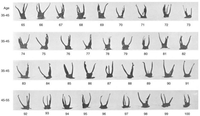
FIG. 9-11 Panel of 36 anatomic preparations of maxillary molars from the classic work by Professor Walter Hess of Zurich. Note the overall variability of root canal systems and the decrease of canal dimensions with age.
(From Hess W: The anatomy of the root canals of teeth of the permanent dentition, London, 1925, John Bale, Sons & Danielsson.)
Unfortunately, canal preparation results are adversely affected by the highly variable root canal anatomy.12,13,188,274,308 This fact is especially true for conventional hand instruments and to a lesser degree for most nickel-titanium rotary instruments.50,301 Therefore the radicular anatomy is briefly reviewed as it pertains to cleaning and shaping.
Root canal curvature can be assessed clinically from radiographs, preferably taken from various angles. However, it is well documented that curves in the mesiodistal plane often are greater than those in the more readily accessible buccal-lingual plane.103,312 In vitro, a full account of three-dimensional canal anatomy can be seen with interactive micro–computed tomographic (µCT) reconstructions (Figs. 9-12 and 9-13).
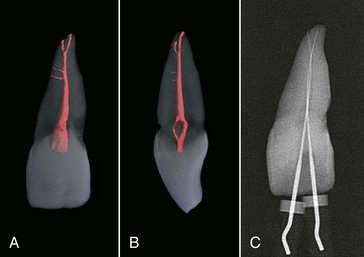
FIG. 9-12 Micro–computed tomographic scans of dental anatomy (36 µm resolution). A, Clinical view of tooth #9 shows two accessory canals and an apical bifurcation. B, Mesiodistal view of the tooth shown in A. C, Working length radiograph, with files placed in both apical canal aspects.
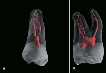
FIG. 9-13 Micro–computed tomographic scans of more complicated dental anatomy (36 µm resolution). A, Clinical view of tooth #3 shows a fine mesiobuccal and distobuccal canal system with additional anatomy in all three roots. B, Mesiodistal view of the tooth shown in A.
The clinician must understand the five commonly encountered canal paths: canals that merge, curve, recurve, dilacerate, or divide.337 All five situations are risk factors for file breakage and should be carefully evaluated, as is done for more basic considerations such as the estimated canal length, position of the primary curve, canal diameter, and apical topography.
Early anatomic studies162,163,219 evaluated the position and topography of the apical foramina and the position of the apical constriction. These studies found that the physiologic foramen, or canal terminus, was located up to 1 mm coronal to the anatomic apex, or root tip. This observation has been confirmed by later studies.123,267
Clinically, the landmark detected from radiographs (the radiographic apex) does not necessarily coincide with the anatomic apex because of projection artifacts. Taken together, these observations suggest that shaping to the radiographic apex is likely to produce overinstrumentation past the apical foramen, with possible clinical sequelae of posttreatment pain and inoculation of microorganisms into periapical spaces.45,47,126,168
Foramen diameter was also an issue in both early162,219 and more recent studies.68,123,267,403 The smallest canal diameter, called the apical constriction, was located 0.5 to 0.7 mm coronal to the canal terminus.162,219 A wide range of diameters has been reported in that region, from 0.2 to about 1 mm68,210-212,219,267; the concept of a single apical constriction has also been challenged.123 Moreover, studies have shown that clinicians usually underestimate apical dimensions.461 Clearly the apical anatomy presents the clinician with major challenges (Fig. 9-14), such as apically dividing canals, nonround cross sections, and deltalike configurations. In addition, canal cross sections that are wide buccolingually458 are difficult to instrument with rotary techniques.
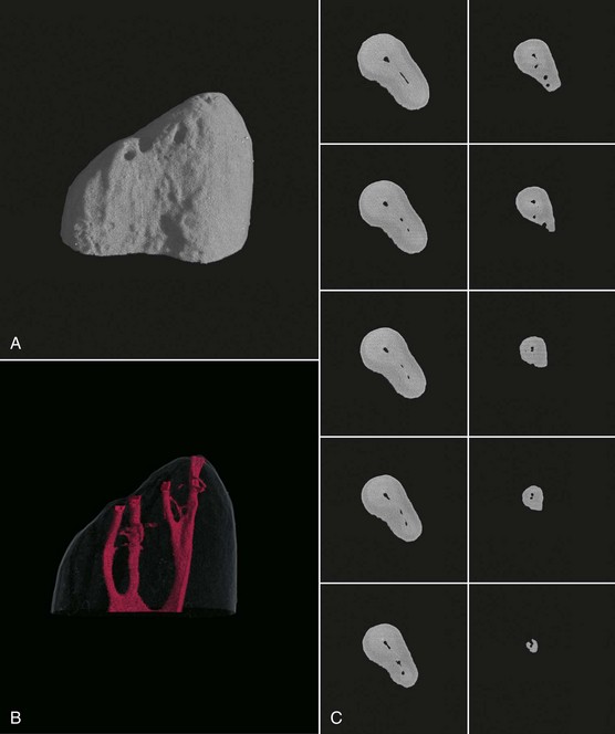
FIG. 9-14 Micro–computed tomographic scan of anatomy of the apical 5 mm of a mesiobuccal root (8 µm resolution). A-B, Three-dimensional reconstruction of outer contour and root canal systems. C, Cross sections 0.5 mm apart.
The clinician must choose the strategies, instruments, and devices to deal with these challenges and control the preparation shape, length, and width precisely. This allows the clinician to use endodontic therapy to address acute (Fig. 9-15) and chronic (Fig. 9-16) forms of the disease processes described previously. Recall radiographs taken at appropriate intervals will demonstrate longevity and favorable outcomes (see Figs. 9-1 to 9-4, 9-6, and 9-16) if clinical objectives are maintained (Box 9-1).
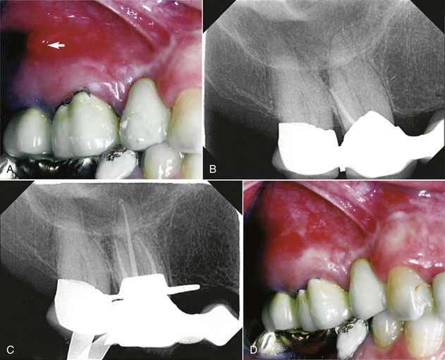
FIG. 9-15 Sinus tract as a sign of a chronic apical abscess and effect of routine root canal treatment. A, Intraoral photograph of left maxillary region with draining sinus tract (arrow) periapical to tooth #14. B, Pretreatment radiograph with gutta-percha point positioned in the sinus tract, pointing toward the distobuccal root of #14. C, Finished root canal fillings after 2 weeks of calcium hydroxide dressing. D, Intraoral photograph of the same region as in A, showing that the sinus tract had closed by the time obturation was performed.
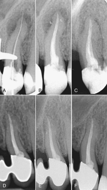
FIG. 9-16 Relationship of radicular anatomy and endodontic disease as shown by filled accessory canals. A, Working length radiograph of tooth #13 shows lesions mesially and distally but not apically. B, Posttreatment radiograph shows the accessory anatomy. C, Six-month recall radiograph before placement of the restoration. D, Two-year recall radiograph after resection of the mesiobuccal root of tooth #14 and placement of a fixed partial denture. Excess sealer appears to have been resorbed, forming a distal residual lesion. E, Four-year recall radiograph shows almost complete bone fill. F, Seven-year recall radiograph; tooth #14 is radiologically sound and clinically within normal limits.
Cleaning and Shaping: Technical Issues
Because several technical issues arise with the instruments and devices used for cleaning and shaping, a short review of these products is provided here (also see Chapter 8). A vast array of instruments, both handheld and engine-driven, are available for root canal preparation. Up to the last decade of the past century, endodontic instruments were manufactured from stainless steel. With the advent of nickel-titanium,370 instrument designs began to vary in terms of taper, length of cutting blades, and tip design. Files traditionally have been produced according to empiric designs, and most instruments still are devised by individual clinicians rather than developed through an evidence-based approach. Similar to the development of composite resins in restorative dentistry, the development of new files is a fast and market-driven process. With new versions rapidly becoming available, the clinician may find it difficult to pick the file and technique most suitable for an individual case. Clinicians must always bear in mind that all file systems have benefits and weaknesses. Ultimately, clinical experience, handling properties, usage safety, and case outcomes, rather than marketing or the inventor’s name, should decide the fate of a particular design.
Hand and Engine-Driven Instruments
Hand instruments have been in clinical use for almost 100 years, and they still are an integral part of cleaning and shaping procedures. A norm established by the American Dental Association (ADA) and the International Standards Organization (ISO)21,117 sets the standards for broaches, K-type files and reamers, Hedström files, and paste carries; however, the term ISO-normed instruments currently is used mainly for K-files (Fig. 9-17). One important feature of these instruments is a defined increase in diameter of 0.05 or 0.1 mm, depending on the instrument size (Fig. 9-18).
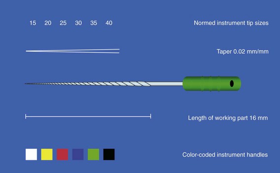
FIG. 9-17 Schematic drawing of an ISO-normed hand instrument size #35. Instrument tip sizing, taper, and handle colors are regulated by the ISO/ANSI/ADA norm.
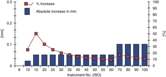
FIG. 9-18 Increase in tip diameter in absolute figures and in relation to the smaller file size. Note the particularly large increase from size #10 to size #15.
Broaches
Barbed broaches are produced in a variety of sizes and color codes. They are manufactured by cutting sharp, coronally angulated barbs into metal wire blanks. Broaches are intended to remove vital pulp from root canals, and in cases of mild inflammation, they work well for severing pulp at the constriction level in toto. The use of broaches has declined since the advent of nickel-titanium rotary shaping instruments, but broaching occasionally may be useful for expediting procedures and removing materials (e.g., cotton pellets or absorbent points) from canals.
K-Files
K-files were manufactured by twisting square or triangular metal blanks along their long axis, producing partly horizontal cutting blades (Fig. 9-19). Noncutting tips, also called Batt tips, are created by grinding and smoothing the apical end of the instrument (see Fig. 9-19). Investigators introduced a modified shape, the Flex-R file, which was manufactured fully by grinding so that the transitional angles were smoothed laterally between the tip and the instrument’s working parts.335 Similar techniques are required to manufacture NiTi K-files413 such as the NiTi-Flex (DENTSPLY Maillefer, Ballaigues, Switzerland). NiTi K-files are extremely flexible and are especially useful for apical enlargement in severe apical curves. They can be precurved, but only with strong overbending; this subjects the file to excess strain and should be done carefully. Because of their flexibility, the smaller NiTi files (sizes up to #25) are of limited use.
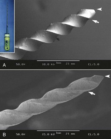
FIG. 9-19 Flute geometry and tip configuration of a hand file (insert) and a NiTi rotary instrument. A, K-file with sharp cutting edges (arrow) and Batt tip (arrowhead). B, GT rotary file with rounded, noncutting tip (arrowhead), smooth transition, and guiding radial lands (arrow).
Cross-sectional analysis of a K-file reveals why this design allows careful application of clockwise and counterclockwise rotational and translational working strokes. ISO-normed K- and Hedström files are available in different lengths (21, 25, and 31 mm), but all have a 16-mm-long section of cutting flutes (see Fig. 9-17). The cross-sectional diameter at the first rake angle of any file is labeled D0. The point 1 mm coronal to D0 is D1, the point 2 mm coronal to D0 is D2, and so on up to D16. The D16 point is the largest diameter of an ISO-normed instrument. Each file derives its numeric name from the diameter at D0 and is assigned a specific color code (see Fig. 9-17).
Another aspect of ISO files is the standard taper of 0.32 mm over 16 mm of cutting blades, or 0.02 mm increase in diameter per millimeter of length (#.02 taper) (see Fig. 9-17). Thus a size #10 instrument has a diameter of 0.1 mm at D0 and a corresponding diameter of 0.42 mm at D16 [0.1 mm + (16 × 0.02 mm)]. For a size #50 instrument, the diameters are 0.5 mm at D0 and 0.82 mm at D16.
The tip size increases by 0.05 mm for file sizes #10 to #60; for sizes #60 to #140, the absolute increase is 0.1 mm (see Fig. 9-18). Recalculation of these diameter increments into relative steps (in percentages) reveals dramatic differences: the step from size #10 to #15 is 50%, whereas the increase from size #55 to #60 is less than one fifth of that change (see Fig. 9-18).
In very small files (sizes #6 to #10), the problem is partly resolved by several key points: (1) apical dimensions are such that a size #6 file does not significantly remove dentin other than in severely calcified cases; (2) a size #8 file taken 0.5 to 1 mm long to establish patency (discussed later in the chapter) contacts the desired endpoint of the preparation with a diameter approaching the tip size of a #10 file; (3) similarly, placing a size #10 file just minutely through the foramen eases the way for passive insertion of the subsequent #15 file to full length.337
The ISO specifications inadvertently complicated the cleaning and shaping of root canal systems. The ISO-normed design is a simplification that has specific disadvantages, and it may explain the clinical observation that enlarging from size #10 to #15 is more difficult than the step from size #55 to #60. The introduction of Golden Medium files (DENTSPLY Maillefer), which have tip sizes between the ISO-stipulated diameters, seemed to solve the problem. However, their use is not that important clinically, because the approved machining tolerance of ± 0.02 mm negates the intended advantage. Moreover, although ± 0.02 mm tolerance is stipulated by the ISO norm (see Fig. 9-17), most manufacturers do not adhere to it.208,365,404,487
A subsequent modification involved tips with a constant percentage of diameter increments, the Series 29. The first ProFile instruments (DENTSPLY Tulsa Dental, Tulsa, OK, USA) followed this design, with a nominal diameter increase of 29%. This sizing pattern creates smaller instruments that carry less of a workload. However, the intended advantage is offset by larger diameters, because the 29% increase between successive files is actually greater than the percentage change found in the ISO file series.
Hedström Files
Hedström files are milled from round, stainless steel blanks. They are very efficient for translational strokes,355 but rotational working movements are strongly discouraged because of the possibility of fracture. Hedström files up to size #25 can be efficiently used to relocate canal orifices and, with adequate filing strokes, to remove overhangs. Similarly, wide oval canals can be instrumented with Hedström files as well as with rotary instruments. On the other hand, overzealous filing can lead to considerable thinning of the radicular wall and strip perforations (Fig. 9-20). As with stainless steel K-files, Hedström files should be single-use instruments.397
Gates-Glidden Drills
Gates-Glidden (GG) drills are important instruments that have been used for more than 100 years without noteworthy design changes. These instruments, especially the nickel-titanium FlexoGates model (DENTSPLY Maillefer),151 usually work well for preenlargement of coronal canal areas.114,261 However, when misused, GG drills can dramatically reduce radicular wall thickness.149,197,239
GG instruments are manufactured in a set and numbered 1 to 6 (with corresponding diameters of 0.5 to 1.5 mm); the number of rings on the shank identifies the specific drill size. GG instruments are available in various lengths and made by several manufacturers. Each instrument has a long, thin shaft with parallel walls and a short cutting head. Because of their design and physical properties,66 GG drills are side-cutting instruments with safety tips; they can be used to cut dentin as they are withdrawn from the canal (i.e., on the outstroke).337 Used this way, their cutting action can deliberately be directed away from external root concavities in single-rooted and furcated teeth.4 GG instruments should be used only in the straight portions of the canal, and they should be used serially and passively.424
Two procedural sequences have been proposed: with the step-down technique, the clinician starts with a large drill and progresses to smaller ones; conversely, with the step-back technique, the clinician starts with a small drill and progresses to larger ones. With the step-down approach, the clinician must select a GG instrument with a diameter that allows introduction into the respective orifice and progression for about 1 mm. The subsequent smaller instruments progress deeper into the canal until the coronal third has been preenlarged. This technique efficiently opens root canal orifices and works best when canals exit the access cavity without severe angulations. Opened orifices simplify subsequent cleaning and shaping procedures and help establish a smooth glide path from the access cavity into the root canal system.
With the step-back approach, a small GG instrument is introduced into the canal, and dentin is removed on the outstroke. This process is repeated with the next larger GG instrument, which is again worked shorter than the preceding smaller one. In this way, the coronal third of the root canal is enlarged and dentin overhangs are removed.
As stated earlier, when used adequately, GG instruments are inexpensive, safe, and clinically beneficial tools. High revolutions per minute (rpm), excessive pressure, an incorrect angle of insertion, and the use of GG instruments to aggressively drill into canals have resulted in mishaps such as strip perforation. Also, cyclic fatigue may cause GG instruments to fracture when used in curved canal areas, and the short cutting heads may fracture with high torsional loads. Gates-Glidden drills may be used safely and to their fullest potential at 750 to 1500 rpm. As with nickel-titanium rotary instruments, GG drills work best when used in electric gear reduction handpieces rather than with air motors.
Nickel-Titanium Rotary Instruments
Since the early 1990s, several instrument systems manufactured from nickel-titanium (NiTi) have been introduced into endodontic practice. The specific design characteristics vary, such as tip sizing, taper, cross section, helix angle, and pitch (Fig. 9-21). Some of the early systems have been removed from the market or play only minor roles; others, such as ProFile (DENTSPLY Tulsa Dental, DENTSPLY Maillefer), are still widely used. New designs continually are produced, but the extent to which clinical outcomes (if any) will depend on design characteristics is difficult to forecast.303
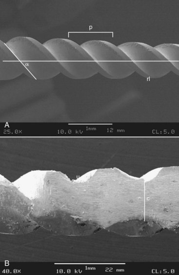
FIG. 9-21 Design characteristics of nickel-titanium rotary instruments. A, Lateral view showing the details of the helix angle, pitch (p), and the presence of guiding areas, or radial lands (rl) (scanning electron micrograph [SEM], ×25). B, Ground working part of the instrument in A, showing U-shaped excavations and the dimension of the instrument core (c).
Most of the instruments described in this section are manufactured by a grinding process, although some are produced by laser etching and others by plastic deformation under heating. Precision at the surface quality is not really at a high level, whereas the tolerances are. Surface quality also is an important detail (see Fig. 9-21), because cracks that arise from superficial defects play a role in instrument fracture.16 Superficial defects such as metal flash and rollover are common in unused NiTi instruments.125,251,489
Attempts have been made to improve surface quality by electropolishing the surface and coating it with titanium nitride.325,353 The latter process also seems to have a beneficial effect on cutting efficiency.353
In essence, two properties of the NiTi alloy are of particular interest in endodontics: superelasticity (Fig. 9-22) and high resistance to cyclic fatigue (discussed later). These two properties allow continuously rotating instruments to be used successfully in curved root canals. Many variables and physical properties influence the clinical performance of NiTi rotaries.218,302,370,413
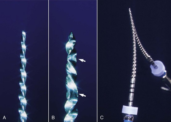
FIG. 9-22 Deformation of endodontic instruments manufactured from nickel-titanium alloy. A and B, Intact and plastically deformed ProFile instruments (arrow indicates areas of permanent deformation). C, ProFile instrument placed on a mirror to illustrate elastic behavior.
Much of what is known about NiTi instruments, including reasons for instrument fracture33 and instrument sequences, has been gleaned from clinical practice. In vitro research continues to clarify the relationship between NiTi metallurgy and instrument performance, but already NiTi rotary instruments have become an important adjunct in endodontics.301
NiTi rotary instruments have substantially reduced the incidence of several clinical problems (e.g., blocks, ledges, transportation, perforation), but they are also believed to fracture somewhat more easily than hand instruments. This does not by itself predispose a case to posttreatment disease; rather, a retained instrument fragment limits access of disinfecting irrigants to the root canal system, possibly impeding sufficient elimination of microorganisms.172
The following sections describe the instruments most widely used in the United States and Europe for root canal preparation. Most basic strategies apply to all NiTi rotary instruments, regardless of the specific design or brand. However, three design groups need to be analyzed separately: group I, the LightSpeed; group II, rotary instruments with #.04 and #.06 tapers, which includes the ProFile and many other models; and group III, rotary instruments with specific design changes, such as the ProTaper (DENTSPLY Maillefer) and RaCe (FKG, La Chaux-de-Fonds, Switzerland).
LightSpeed and LightSpeed LSX Instruments
The LightSpeed file, developed by Dr. Steve Senia and Dr. William Wildey in the early 1990s and now also known as LS1, was introduced as an instrument different from all others because of its long, thin noncutting shaft and short anterior cutting part. The same design principles apply to the recently developed LSX instrument (Discus Dental, Culver City, CA, USA) (Fig. 9-23) that is manufactured not by milling but by stamping. A full set consists of 25 LightSpeed LS1 instruments in sizes #20 to #100, including half sizes (e.g., 22.5, 27.5); LSX does not have half sizes, and a set includes sizes #20 to #80.

FIG. 9-23 Design features of a LightSpeed instrument. A, Lateral view (scanning electron micrograph [SEM], ×50). B, Cross section (SEM, ×200). C, Lateral view. D, Design specifications.
The recommended working speed for LS1 instruments is 1500 to 2000 rpm and for LSX, 2500 rpm. Both variants should be used with minimal torque,32 owing to the thin shaft.120
Cross sections of LightSpeed LS1 cutting parts show three round excavations, the U-shape design common to many earlier NiTi instruments, whereas the LSX is shaped like a flat chisel in cross section (see Fig. 9-23). Because of the thin noncutting shaft, both types of LightSpeed instruments are considerably more flexible than any other instrument on the market. In addition, cyclic fatigue is lower than with all other instruments, allowing the use of higher rpm speeds. All LightSpeed instruments feature a noncutting tip.
Because of their design, LightSpeed LS1 and LSX require specific instrumentation sequences to produce canal shapes amenable to root canal filling. The current recommendation calls for an apical 4-mm zone to be prepared to a cylindrical, nontapered shape. This section may then be filled with the proprietary SimpliFill system (Discus Dental). Different sequences are required for lateral compaction or other filling techniques.
The original LightSpeed is a widely researched NiTi rotary instrument,49,319,321,375,415,416 and most reports have found that the system has a low incidence of canal transportation and preparation errors. Loss of working length was also minimal in most of these studies. Data regarding the LSX are sparse. One report found similar shaping abilities for LSX and LightSpeed LS1 assessed with a double-exposure technique.196
ProFile
The ProFile system (DENTSPLY Tulsa Dental) was introduced by Dr. Ben Johnson in 1994. In contrast to the LightSpeed instrument with its thin, flexible shaft, ProFile instruments have increased tapers compared with conventional hand instruments. The ProFile system was first sold as the “Series 29” hand instruments in .02 taper, but it soon became available in .04 and .06 taper (Fig. 9-24). The tips of the ProFile Series 29 rotary instruments had a constant proportion of diameter increments (29%). Because of the nonstandardized diameters, obturation was performed with nonstandardized gutta-percha cones, using either lateral compaction or thermoplastic obturation of gutta-percha (see Chapter 10). Later, another ProFile series with ISO-sized tips (DENTSPLY Maillefer) was developed and marketed in Europe. This set was believed to better accommodate standardized gutta-percha cones, which are predominantly used in Europe. Subsequently, instruments with even greater tapers and 19-mm lengths were introduced, and a .02 variant was added.
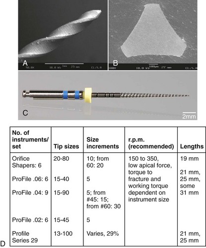
FIG. 9-24 Design features of a ProFile instrument. A, Lateral view (scanning electron micrograph [SEM], ×50). B, Cross section (SEM, ×200). C, Lateral view. D, Design specifications.
Cross sections of a ProFile instrument show a U-shape design with radial lands and a parallel central core. Lateral views show a 20-degree helix angle, a constant pitch, and bullet-shaped noncutting tips. Together with a neutral or slightly negative rake angle, this configuration facilitates a reaming action on dentin rather than cutting. Also, debris is transported coronally and is effectively removed from the root canals.
The recommended rotational speed for ProFile instruments is 150 to 300 rpm, and to ensure a constant rpm level, the preferred means is electrical motors with gear reduction rather than air-driven motors.
ProFile instruments shaped canals without major preparation errors in a number of in vitro investigations.72,73,417,418 A slight improvement in canal shape was noted when size .04 and .06 tapered instruments were used in an alternating fashion.71 Loss of working length did not exceed 0.5 mm71-73,417,418 and was not affected by the use of .06 tapered instruments.71 Comparative assessments in vitro suggested that ProFile prepared mesial canals in mandibular molars with less transportation than K3 and RaCe.14
A very recent addition to the ProFile family of instruments is the Vortex (DENTSPLY Tulsa Dental). The major change lies in the non-landed cross section, whereas tip sizes and tapers are similar to existing ProFiles. Manufactured using M-Wire, Profile Vortex also have varying helical angle to counteract the tendency of non-landed files to thread into the root canal. At this point, comparatively little clinical or experimental data are available for ProFile Vortex.
GT and GTX Files
The Greater Taper, or GT file, was introduced by Dr. Steve Buchanan in 1994. This instrument also incorporates the U-file design and was marketed as ProFile GT. The system was first produced as a set of four hand-operated files and later as engine-driven files. The instruments came in four tapers (.06, .08, .10, and .12), and the maximum diameter of the working part was 1 mm. This decreased the length of the cutting flutes and increased the taper. The instruments had a variable pitch and an increasing number of flutes in progression to the tip; the apical instrument diameter was 0.2 mm. Instrument tips were noncutting and rounded (Fig. 9-25); these design principles are mostly still present in the current incarnation, the GTX instrument. The main differences are the NiTi alloy type used (M-Wire, manufactured by SportsWire, Langley, OK) and a different approach to instrument usage, emphasizing the use of the #20 .06 rotary.
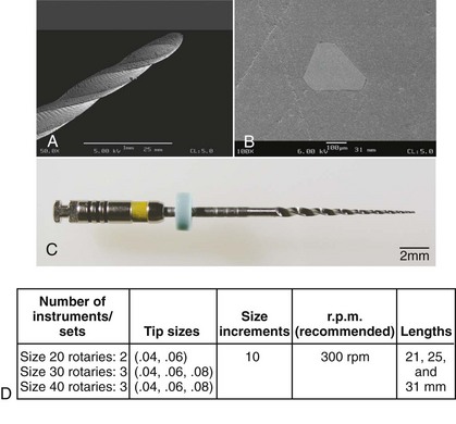
FIG. 9-25 Design features of a GT-file. A, Lateral view (scanning electron micrograph [SEM], ×50). B, Cross section (SEM, ×200). C, Lateral view. D, Design specifications.
The GTX set currently includes tip sizes 20, 30, and 40, in tapers ranging from .04 to .010 (see Fig. 9-25). The recommended rotational speed for GT and GTX files is 300 rpm, and the instrument should be used with minimal apical force to avoid fracture of the tip.
Studies on GT files found that the prepared shape stayed centered and was achieved with few procedural errors.149,178,310,316,479 A shaping assessment using µCT showed that GT files machined statistically similar canal wall areas compared with ProFile and LightSpeed preparations.310 These walls were homogeneously machined and smooth.294,479
HERO 642, Hero Shaper
First-generation rotary systems had neutral or slightly negative rake angles. Several second-generation systems were designed with positive rake angles, which gave them greater cutting efficiency. HERO instruments (MicroMega, Besançon, France) are an example of a second-generation system; the original system known as HERO 642 has now been replaced by HERO Shaper, with very little difference in the instrument design.
Cross sections of HERO instruments show geometries similar to those of an H-file without radial lands (Fig. 9-26). Tapers of .02, .04, and .06 are available in sizes ranging from #20 to #45. The instruments are relatively flexible (the acronym HERO stands for high elasticity in rotation) but maintain an even distribution of force into the cutting areas.430,431 HERO instruments have a progressive flute pitch and a noncutting passive tip, similar to other NiTi rotary systems. The instruments are coded by handle color.
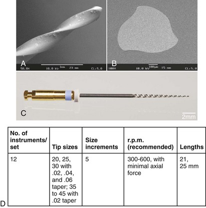
FIG. 9-26 Design features of a HERO instrument. A, Lateral view (scanning electron micrograph [SEM], ×50). B, Cross section (SEM, ×200). C, Lateral view. D, Design specifications.
Research with HERO files indicates a shaping potential similar to that of the FlexMaster189 (DENTSPLY VDW, Munich, Germany) and the ProFile,147 although in one study the HERO induced more changes in cross-sectional anatomy.157 HERO instruments also were found to cause some aberrations when used in simulated canals with acute curves414 but were safer than Quantec SC instruments (SybronEndo, Orange, CA).193 More recently, HERO Shapers were found to have a better centering ability compared to RaCe instruments in resin blocks.28 Comparing earlier HERO 642 and current HERO Shaper rotaries, no differences were found assessing cross sections before and after shaping in a modified Bramante technique.84
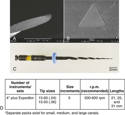
ProTaper Universal
The ProTaper system is based on a unique concept and originally comprised just six instruments: three shaping files and three finishing files. This set is now complemented by two larger finishing files and a set designed for retreatment procedures. The instruments were designed by Dr. Cliff Ruddle, Dr. John West, and Dr. Pierre Machtou. In cross section, ProTaper shows a modified K-type file with sharp cutting edges and no radial lands (Fig. 9-27); this creates a stable core and sufficient flexibility for the smaller files. The cross section of finishing files F3, F4, and F5 is slightly relieved for increased flexibility. A unique design element is varying tapers along the instruments’ long axes. The three shaping files have tapers that increase coronally, and the reverse pattern is seen in the five finishing files.
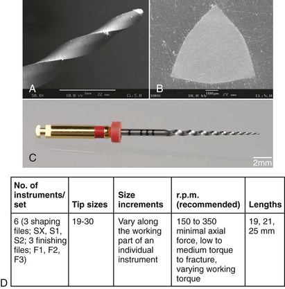
FIG. 9-27 Design features of a ProTaper instrument. A, Lateral view (scanning electron micrograph [SEM], ×50). B, Cross section (SEM, ×200). C, Lateral view. D, Design specifications.
Shaping files #1 and #2 have tip diameters of 0.185 mm and 0.2 mm, respectively, 14-mm-long cutting blades, and partially active tips. The diameters of these files at D14 are 1.2 and 1.1 mm, respectively. The finishing files (F1-F5) have tip diameters of 0.2, 0.25, 0.3, 0.4, and 0.5 mm, respectively, between D0 and D3, and the apical tapers are .07, .08, .09, .05, and .04, respectively. The finishing files have rounded noncutting tips.
The convex triangular cross section of ProTaper instruments reduces the contact areas between the file and the dentin. The greater cutting efficiency inherent in this design has been safely improved by balancing the pitch and helix angle, preventing the instruments from inadvertently threading into the canal. The instruments are coded by colored rings on the handles. ProTaper instruments can be used in gear reduction electrical handpieces at 250 to 300 rpm, in accordance with universally recognized guidelines. Two usage characteristics have been recommended for ProTaper. The first is the preparation of a glide path, either manually298 or with special rotary instruments.52 An enlargement to a size approaching the subsequent rotaries’ tips prevents breakage and allows assessment of the canal size.298 The second specific recommendation is the use of a more lateral “brushing” working stroke. Such a stroke allows the clinician to direct larger files coronally away from danger zones and counteract any “threading-in” effect.58 Both usage elements should be considered good practice for other instruments, particularly more actively cutting ones.314
In a study using plastic blocks, the ProTaper created acceptable shapes more quickly than GT rotary, ProFile, and Quantec instruments479 but also created somewhat more aberrations. This was recently corroborated comparing preparations of mesial root canals in mandibular molars ex vivo with ProTaper Universal to Alpha (Brasseler Komet, Lemgo, Germany).440 In a comparison of ProTaper and K3 instruments (SybronEndo, Orange, CA), Bergmans et al.48 found few differences, with the exception of some transportation by the ProTaper into the furcation region. A study using µCT showed that the ProTaper created consistent shapes in constricted canals, without obvious preparation errors, although wide canals may be insufficiently prepared with this system.308 It has been recommended that ProTaper be combined with less tapered, more flexible rotaries to reduce apical transportation.199
K3
In a sequence of constant development by their inventor, Dr. McSpadden, the Quantec 2000 files were followed by the Quantec SC, the Quantec LX, and the current K3 system (all by SybronEndo). The overall design of the K3 is similar to that of the ProFile and the HERO in that it includes instruments with .02, .04, and .06 tapers. The most obvious difference between the Quantec and K3 models is the K3’s unique cross-sectional design (Fig. 9-28): a slightly positive rake angle for greater cutting efficiency, wide radial lands, and a peripheral blade relief for reduced friction. Unlike the Quantec, a two-flute file, the K3 features a third radial land to help prevent threading-in.
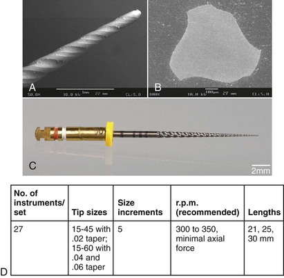
FIG. 9-28 Design features of a K3 instrument. A, Lateral view (scanning electron micrograph [SEM], ×50). B, Cross section (SEM, ×200). C, Lateral view. D, Design specifications.
In the lateral aspect, the K3 has a variable pitch and variable core diameter, which provide apical strength. This complicated design is relatively difficult to manufacture, resulting in some metal flash (see Fig. 9-28).
Like most other instruments, the K3 features a round safety tip, but the file is about 4 mm shorter than other files (although it has the same length of cutting flutes) because of the Axxess handle. The instruments are coded by ring color and number.
Tested in vitro, K3’s shaping ability seems to be similar to that of the ProTaper48 and superior to that achieved with hand instruments.357 More recently, when curved canals in lower molars were shaped to a size #30 .06,14 K3 had less canal transportation in a modified Bramante model than RaCe but more than ProFile.
FlexMaster
The FlexMaster file system currently is unavailable in the United States. It also features .02, .04, and .06 tapers. The cross sections (Fig. 9-29) have a triangular shape, with sharp cutting edges and no radial lands. This makes for a relatively solid instrument core and excellent cutting ability. The overall manufacturing quality is high, with minimal metal flash and rollover.
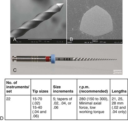
FIG. 9-29 Design features of a FlexMaster instrument. A, Lateral view (scanning electron micrograph [SEM], ×50). B, Cross section (SEM, ×200). C, Lateral view. D, Design specifications.
FlexMaster files have rounded, passive tips; the tip diameters are 0.15 to 0.7 mm for size .02 instruments and 0.15 to 0.4 mm for size .04 and .06 files (see Fig. 9-29). In addition to the standard set, the Intro file, which has a .11 taper and a 9-mm cutting part, is available. The instruments are marked with milled rings on the instrument shaft, and the manufacturer provides a system box that indicates sequences for narrow, medium-size, and wide canals.
Several studies indicate that the FlexMaster allows centered preparations in both constricted and wider canals188 and that it performed on par with other systems.189,455 Clinical studies confirmed that the FlexMaster showed superior shaping characteristics compared with K-files.358 Also, novice dental students were able to shape plastic blocks successfully with the FlexMaster after a short training period.392,393 Tested in a well-described model of simulated canals, FlexMaster instruments led to few aberrations but took longer than preparation with RaCe files.263 Moreover, FlexMaster appeared to be less effective than RaCe in removing dye from the walls of simulated canals prepared to size #30 but were more effective than ProFile.362
RaCe, Bio Race
The RaCe has been manufactured since 1999 by FKG and was later distributed in the United States by Brasseler (Savannah, GA). The name, which stands for reamer with alternating cutting edges, describes just one design feature of this instrument (Fig. 9-30). Light microscopic imaging of the file shows flutes and reverse flutes alternating with straight areas; this design is aimed at reducing the tendency to thread the file into the root canal. Cross sections are triangular or square for #.02 instruments with size #15 and #20 tips. The lengths of cutting parts vary from 9 to 16 mm (see Fig. 9-30).
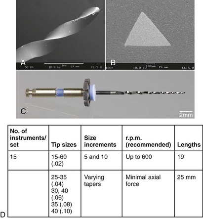
FIG. 9-30 Design features of an RaCe instrument. A, Lateral view (scanning electron micrograph [SEM], ×50). B, Cross section (SEM, ×200). C, Lateral view. D, Design specifications.
The surface quality of RaCe instruments has been modified by electropolishing, and the two largest files (size #35, #.08 taper and size #40, #.10 taper) are also available in stainless steel. The tips are round and noncutting, and the instruments are marked by color-coded handles and milled rings. RaCe instruments have been marketed in various packages to address small and large canals; recently they are sold as BioRaCe, purportedly to allow preparations two larger sizes, with an emphasis on the use of .02 tapered instruments.
Few results of in vitro experiments comparing RaCe to other contemporary rotary systems are available359,360: canals in plastic blocks and in extracted teeth were prepared by the RaCe with less transportation from the original curvature than occurred with the ProTaper.359 In a separate study, ProTaper and RaCe performed similarly when canals were prepared to an apical size #30.293 When preparing to a size #40, RaCe prepared canals rapidly and with few aberrations or instrument deformities.324 The newer BioRaCe instrument sequences attempt to utilize .02 tapered instruments to promote larger apical sizes; this is also possible in a hybrid technique.
EndoSequence
The Sequence rotary instrument is produced by FKG in Switzerland and marketed in the United States by Brasseler. This is another instrument that adheres to the conventional length of the cutting flutes, 16 mm, and to larger tapers, .04 and .06, to be used in a crown-down approach. The overall design, including the available tapers and cross sections, is thus similar to many other files (Fig. 9-31), but the manufacturer claims that a unique longitudinal design called alternating wall contact points (ACP) reduce torque requirements and keep the file centered in the canal. Another feature of the Sequence design is an electrochemical treatment after manufacturing, similar to RaCe files, that results in a smooth, polished surface. This is believed to promote better fatigue resistance, hence a rotational speed of 600 rpm is recommended for EndoSequence.214
Twisted File
In 2008, SybronEndo presented the first fluted NiTi file (Fig. 9-32, A) manufactured by plastic deformation, a process similar to the twisting process that is used to produce stainless steel K-files. According to the manufacturer, a thermal process allows twisting during a phase transformation into the so-called R-phase of nickel-titanium. The instrument is currently available with size #25 tip sizes only, in taper .04 up to .12.
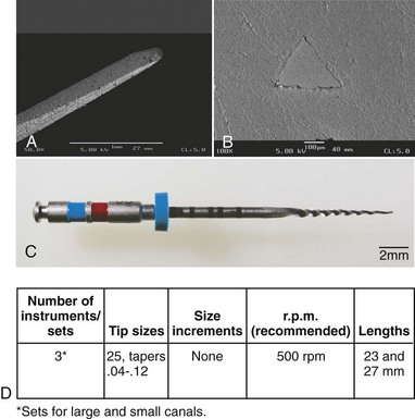
FIG. 9-32 Design features of a Twisted File (TF) instrument. A, Lateral view (scanning electron micrograph [SEM], ×50). B, Cross section (SEM, ×200). C, Lateral view. D, Design specifications.
The unique production process is believed to result in superior physical properties; indeed, early studies suggested significantly better fatigue resistance of size #25 .06 taper Twisted File compared to K3 instruments of the same size and size #20 .06 GTX.146 Moreover, as determined by bending tests according to the norm for hand instruments, ANSI/ADA No. 28 (ISO 3630), Twisted Files size #25 .06 taper were more flexible than ProFiles of the same size.145
The manufacturer recommends a conventional crown-down technique after securing a glide path with a size #15 K-file. Specifically, for a “large” canal, tapers .10 to .06 should be used, and in a “small” canal, tapers .08 to .04 are recommended. Although early reports suggest that the Twisted File is clinically resistant to fatigue, there are no reports available at this point that show improved healing outcomes compared to other rotary files.
The preceding descriptions covered only a limited selection of the most popular and widely used rotary instruments on the market. New files are continually added to the armamentarium, and older systems are updated. This is partly the reason for the scarcity of clinical outcome studies at this point.
To summarize, most systems include files with tapers greater than the #.02 stipulated by the ISO norm. The LightSpeed LS1 and LSX are different from all other systems; the ProTaper, RaCe, and Twisted File have some unique features; and most other systems have increased tapers. Minor differences exist in tip designs, cross sections, and manufacturing processes, but the clinical effects of these modifications currently are unknown. Even in vitro, tests have only begun to identify the effect of specific designs on shaping capabilities,50,192,301 and differences in clinical outcomes in regard to these design variations appear to be minimal.165,303,358
Physical parameters governing rotary root canal preparation are crucial because NiTi rotary files are felt to have an increased risk of fracture compared with K-files. In a study using plastic blocks, as many as 52 ProFile Series 29 instruments became permanently deformed.417 Three fractures were reported in a subsequent study on ISO-norm ProFile size #.04 instruments, and three other instruments were distorted.73 An even higher fracture incidence was shown in a study on rotary instruments used in plastic blocks in a specially designed testing machine.412 These findings were supported by two studies in which high fracture incidences were reported for LightSpeed and Quantec rotary instruments used in a clinical setting.33,345
On the other hand, a retrospective clinical study suggest similar outcomes with and without retained instrument fragments400; moreover, others’ experiences suggest that the number of rotary instrument fractures is lower than previously estimated.116,213,460 Removal of such fragments is possible in many situations, but there is also the potential for further damage (e.g., perforation) rather than successful removal.405,453
Consequently, a benefit-versus-risk analysis should be carried out prior to attempts to remove NiTi instrument fragments, addressing the reasons and the clinical consequences of instrument fracture.
Physical and Chemical Properties of NiTi Alloys
During the development of the equiatomic nitinol alloy (55% [by weight] nickel and 45% [by weight] titanium), a shape memory effect was noted; this was attributed to specific thermodynamic properties of the new alloy.75 The alloy sparked interest in dental research because of its “shape recovery” property after passage through critical temperatures.100 Some researchers envisioned the manufacture of nondulling rotary instruments from an alloy called 60-nitinol. However, NiTi wire was found to be difficult to bend into clamp retainers.100
Subsequently, researchers thought that the superelastic properties of 55-nitinol might prove advantageous in endodontics, and the first hand instruments produced from 55-nitinol were tested (Fig. 9-33).445 That study found that size #15 NiTi instruments were two to three times more flexible than stainless steel instruments. Nickel-titanium instruments showed superior resistance to angular deflection; they fractured after  full revolutions (900 degrees) compared to 540 degrees for stainless steel instruments (see Fig. 9-33, C).
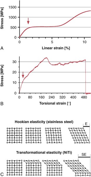
FIG. 9-33 Stress-strain behavior of nickel-titanium alloy. A, Schematic diagram of linear extension of a NiTi wire. B, Torque to failure test of a size #60, #.04 taper ProFile NiTi instrument. Note the biphasic deformation, indicated by arrows in A-B. C, Comparison of stainless steel and nickel-titanium crystal lattices under load. Hookian elasticity accounts for the elastic behavior (E) of steel, whereas transformation from martensite to austenite and back occurs during the superelastic (SE) behavior of NiTi alloy.
(C modified from Thompson SA: An overview of nickel-titanium alloys used in dentistry. Int Endod J 33:297-310, 2000.)
Furthermore, hardly any plastic deformation of cutting flutes was recorded when an instrument was bent up to 90 degrees,445 and forces required to bend endodontic files to 45 degrees were reduced by 50% with NiTi.370 In the latter study, the authors speculated that heat, probably during sterilization cycles, could even restore the molecular structure of used NiTi files, resulting in an increased resistance to fracture.
Specific properties of NiTi can be explained by specific crystal structures of the austenite and martensite phases of the alloy.413 Heating the metal above 212° F (100° C) may lead to a phase transition, and the shape memory property forces the instrument back to a preexisting form. Likewise, linear deforming forces are shunted into a stepwise transition from an austenitic to a martensitic lattice, and this behavior leads to a recoverable elastic response of up to 7% (see Fig. 9-33, A).
However, graphs such as those shown in Fig. 9-33, B are generated when larger NiTi instruments are subjected to angular deflection until failure. Such graphs show different results for stainless steel instruments, which produce a relatively steep stress-strain curve with less than 1.3% recoverable deformation.413 As stated previously, the superelastic behavior of NiTi also dictates the production of NiTi instruments, which are usually milled.
Similarly to phase transformations induced by strain, heating and cooling NiTi can also result in conformational changes.179,265 Thermal conditions during the production of the raw wire can be used to modify its properties—most importantly, its flexibility.
Recently, such a thermal process was harnessed to allow twisting of raw NiTi material into the shape of a nonlanded rotary instrument (Twisted File, SybronEndo). This process is believed to respect the grain structure of the material better and does not introduce milling marks or other surface irregularities.
Typically, NiTi instruments may have characteristic imperfections such as milling marks, metal flashes, or rollover.125,370,426,445 Some researchers have speculated that fractures in NiTi instruments originate at such surface imperfections.16,237
Surface irregularities may also provide access to corrosive substances, most notably sodium hypochlorite (NaOCl). Some studies have suggested that chloride corrosion may lead to micropitting344 and possibly subsequent fracture in NiTi instruments.174 Not only immersion in various disinfecting solutions for extended periods (e.g., overnight) produced corrosion of NiTi instruments and subsequent decreased torsional resistance,284,394 but for ProTaper,51 RaCe, and ProFile309 instruments, also short-term immersion. Other authors, however, did not find a corrosion-related effect on K335 or ProFile257 instruments. Regular cleaning and sterilization procedures do not seem to affect NiTi rotary instruments.231,266,406 In one study, only limited material loss occurred when NiTi LightSpeed instruments were immersed in 1% and 5% NaOCl for 30 to 60 minutes.78 Corrosion of NiTi instruments used in the clinical setting, therefore, might not significantly contribute to fracture except when the instruments are immersed in warmed NaOCl for longer than 60 minutes. Although sterilization procedures per se do not have an impact on NiTi integrity,184,266,326,377,442,489 there is an ongoing discussion over the impact of other aspects of clinical usage on the mechanical properties of NiTi rotaries. Most likely, clinical usage leads to some changes in the alloy, potentially work-hardening,15 depending on the amount of torsional load the instrument was subjected to.
Over the last 4 years, several manufacturers have begun to utilize electropolishing, a process that removes surface irregularities such as flash and burr marks. It is believed to improve material properties, specifically fatigue and corrosion resistance; however, the evidence for both these claims is mixed. One study24 found an extension of fatigue life for electropolished instruments, others found no improvement of fatigue resistance of electropolished instruments.76,94,182 Still other researchers59 suggested a change in cutting behavior with an increase of torsional load after electropolishing. Corrosion resistance of electropolished NiTi rotaries is also controversial. One study62 found superior corrosion resistance for electropolished RaCe instruments, whereas another study309 found similar corrosion susceptibility for RaCe and non-electropolished ProFile instruments. A recent review374 points out difficulties in assessing NiTi properties by conventional corrosion tests, since they do not take deformation and consequent surface deformation into account.
Fracture Mechanisms
In general, instruments used in rotary motion break in two distinct modes, torsional and flexural.302,345,433 Torsional fracture occurs when an instrument tip is locked in a canal while the shank continues to rotate, thereby exerting enough torque to fracture the tip. This also may occur when instrument rotation is sufficiently slowed in relation to the cross-sectional diameter. In contrast, flexural fracture occurs when the cyclic loading leads to metal fatigue. This problem precludes the manufacture of continuously rotating stainless steel endodontic instruments, because steel develops fatal fatigue after only a few cycles.370 NiTi instruments can withstand several hundred flexural cycles before they fracture,173,227,321,433,475 but they still can fracture in the endodontic setting after a low (i.e., below 10,000) number of cycles.92
Repeated loading and cyclic fatigue tests for endodontic instruments are not described in pertinent norms. Initially, rotary instruments such as Gates-Glidden burs and Peeso reamers were tested with a superimposed bending deflection.66 In GG burs, a 2-mm deflection of the instrument tip resulted in fatigue lifespans ranging from 21,000 revolutions (size #1 burs) to 400 revolutions (size #6 burs).66 In another study, stainless steel and NiTi hand files were rotated to failure in steel tubes with an acute 90-degree bend and an unspecified radius.370 Under these conditions, size #40 stainless steel instruments fractured after fewer than 20 rotations, whereas various NiTi files of the same size withstood up to 450 rotations.
Cyclic fatigue was also evaluated for ProFile size #.06 instruments using a similar device.474,475 The number of rotations to failure for unused control instruments ranged from 1260 (size #15 files) to 900 (size #40 files). These scores did not change when the instruments were tested under simulated clinical conditions such as repeated sterilization and contact with 2.5% NaOCl. Subsequently, control instruments were compared with a group of instruments used in the clinical setting in five molar cases474; again, no significant differences were found in resistance to cyclic fatigue.
One study173 used a different testing method involving tempered metal cylinders with radii of 5 mm and 10 mm that produced a 90-degree curve. They reported fatigue fractures for size #15, #.04 taper ProFile instruments after about 2800 cycles with the 10 mm cylinders. In size #40, #.04 taper ProFile instruments, fractures occurred after about 500 cycles with the 5-mm cylinders. In comparison, size #15, #.06 taper ProFile instruments also failed after about 2800 revolutions with the 10-mm cylinders, but failure occurred in size #40, #.06 taper ProFile specimens after only 223 cycles with the 5-mm cylinders.
Rotary NiTi instruments with larger tapers and sizes consistently fractured after fewer rotations,313 and although the radius of the curves was halved, fatigue-life was reduced by 400%. Another investigation173 reported similar results for selected HERO instruments, and their findings were confirmed by other tests on GT rotary instruments. Size #20, #.06 taper GT files failed after 530 rotations in a 90-degree curve with a 5-mm radius; size #20, #.12 taper GT files failed after 56 rotations under the same conditions.306
Reuse of rotary instruments depends on safety, specifically on assessment of fatigue and also the potential to properly clean NiTi surfaces.34,61,284,289,376,394,396,427 Specific instruments perform differently in this regard, since fatigue depends more on the amount of metal in cross section at the point of stress concentration159,425 than on the specifics of instrument design.93
On the other hand, manufacturers claim that their instrument has been equipped with design elements that render it more fatigue resistant. For example, LightSpeed LSX is manufactured without a milling process. However, no data have been published regarding its fatigue resistance. GTX is manufactured from a novel NiTi alloy, M-Wire, to increase its fatigue resistance.203 However, investigators216 could not confirm these findings. Similarly, another study223 did not find the Twisted File, which is not milled and hence believed to be fatigue resistant,146 to perform better than conventionally manufactured ProFile rotaries. Another feature, electropolishing (see earlier) does not appear to confer a significantly increased fatigue resistance to EndoSequence223,328 and RaCe.425,427,471 One possible reason for these variable outcomes are the different testing environments used in vitro95; clinically, even greater variability is to be expected.
Attempts have been made to use tests according to norms and specifications described for stainless steel hand instruments such as K-files and Hedström files,117 since no comparable norms exist for instruments used in continuous rotary motion. Consequently, a number of models have been devised to assess specific properties of NiTi rotary instruments, including torque at failure, resistance against cyclic fatigue, and others (Fig. 9-34). These systems can simultaneously assess torque at failure, working torque axial force, and cyclic fatigue (Fig. 9-35).
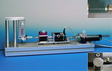
FIG. 9-34 Testing platform for analysis of various factors during simulated canal preparation with rotary endodontic instruments. Labeled components are a force transducer (A), a torque sensor (B), a direct-drive motor (C), and an automated feed device (D). For specific tests, a cyclic fatigue phantom or a brass mount compliant with ISO No. 3630-1 (inserts) may be attached.
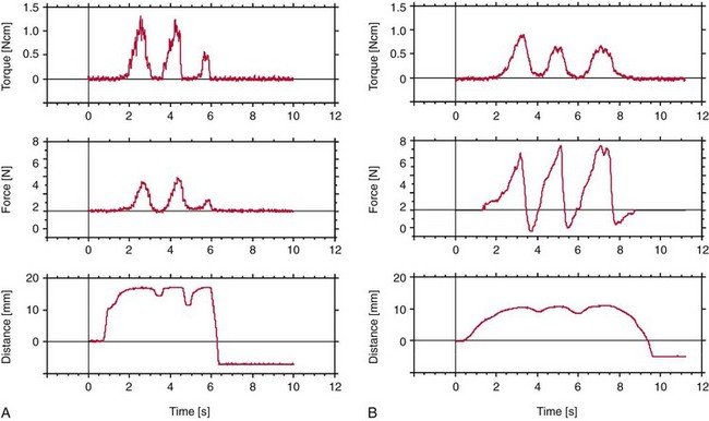
FIG. 9-35 Physical factors (torque, axial force, and insertion depth) that affect root canal instrumentation documented with a torque-testing platform. A, ProFile size #45, #.04 taper used in a mildly curved canal of a single-rooted tooth, step-back after apical preparation to size #40. B, FlexMaster size #35, #.06 taper used in a curved distobuccal canal of a maxillary first molar, crown-down during the initial phase of canal preparation.
According to the norms mentioned previously, torque at failure is recorded with the apical 3 mm of the instrument firmly held in the testing device while the instrument’s handle is rotated. A wide variety of rotary NiTi endodontic instruments have been tested in this way. For example, ProFile NiTi rotary files in ISO sizes #25, #30, and #35 (#.04 taper) fractured at 0.78, 1.06, and 1.47 Ncm, respectively.406
Investigators407 reported similar scores when instruments were forced to fracture in plastic blocks with simulated curved canals. In a different setup, GT rotary instruments (size #20, #.06 taper to size #20, #.12 taper) fractured at 0.51 and 1.2 Ncm, respectively.306 These values are somewhat lower than recent data obtained from the same but slightly modified torque bench,209 pointing towards the importance of experimental conditions for torque and fatigue measurements.
Compared with NiTi instruments with tapered flutes, LightSpeed instruments had lower torques to fracture (0.23 to 2 Ncm254). No such data are currently available for Lightspeed LSX.
When analyzing clinical factors involved in instrument fracture, one must consider both torsional load and cyclic fatigue345 (Fig. 9-36). However, these are not separate entities, especially in curved canals.63 Working an instrument with high torque may lower resistance to cyclic fatigue.142 Conversely, cyclic prestressing has been shown to reduce the torsional resistance of ProTaper finishing files,433 as well as K330 and MTwo313 (DENTSPLY VDW, Munich, Germany). Also, cyclic fatigue occurs not only in the lateral aspect when an instrument rotates in a curved canal but also axially when an instrument is bound and released by canal irregularities.54
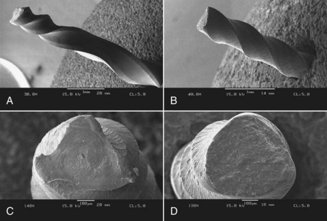
FIG. 9-36 Scanning electron micrographs of deformed or separated nickel-titanium rotary instruments. A, Lateral view of a ProTaper F3 instrument after application of torsional load (×25). B, Lateral view of a size #35, #.04 taper FlexMaster instrument after more than 500 rotations in a 90-degree curve with a 5-mm radius (see Figure 9-31) (×30). C, Cross section of the ProTaper instrument in A. Note signs of ductile fracture near center of the instrument core (×140). D, Cross section of FlexMaster instrument in B (×100).
The torque generated during canal preparation depends on a variety of factors, and an important one is the contact area.57 The size of the surface area contacted by an endodontic instrument is influenced by the instrumentation sequence or by the use of instruments with different tapers.364 A crown-down approach is recommended to reduce torsional loads (and thus the risk of fracture) by preventing a large portion of the tapered rotating instrument from engaging root dentin (known as taper lock).57,476
The clinician can further modify torque by varying axial pressure, because these two factors are related364 (see Fig. 9-35). In fact, a light touch is recommended for all current NiTi instruments to avoid forcing the instrument into taper lock. The same effect might occur in certain anatomic situations, such as when canals merge, dilacerate, and divide.
The torsional behavior of NiTi rotary endodontic instruments cannot be described properly without advanced measurement systems and a new set of norms. However, the clinician must be able to interpret correctly the stress-strain curves for all rotary NiTi instruments used in the clinical setting to be able to choose an appropriate working torque and axial force.
Motors and Devices
Newer motors have been developed for rotary instruments since the simple electric motors of the first generation in the early 1990s (Fig. 9-37, A). Electric motors with gear reduction are more suitable for rotary NiTi systems because they ensure a constant rpm level; however, they also deliver torques much higher than those required to break tips. Some authors believe that torque-controlled motors (see Fig. 9-37, B to D), which have been used for several years, increase operational safety.143 However, others have suggested that torque-control motors may be helpful mainly to inexperienced clinicians.476 These motors probably do not reduce the risk of fracture caused by cyclic fatigue, and even if the torque is below the fracture load at D3, a fracture at a smaller diameter (D2) is still possible.
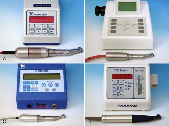
FIG. 9-37 Examples of motors used with rotary nickel-titanium endodontic instruments. A, First-generation motor without torque control. B, Fully electronically controlled second-generation motor with sensitive torque limiter. C, Frequently used simple torque-controlled motor. D, Newest-generation motor with built-in apex locator and torque control.
To complicate matters further, an obvious differential exists between torque at failure at D3 and the working torque needed to operate an instrument effectively (Fig. 9-38 and Box 9-2).58,187,302,307,346 In many cases, the working torque is greater than the torque required to fracture the instrument’s tip. However, the tip will not break if a passive glide path has been verified.
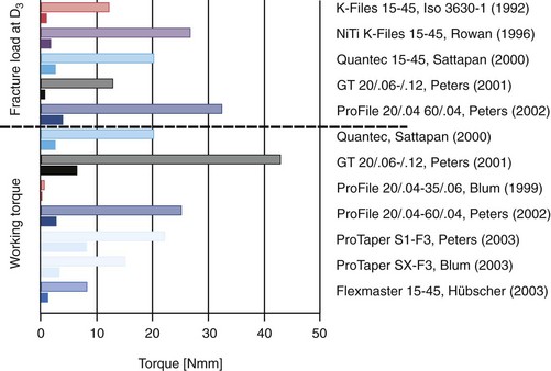
FIG. 9-38 Diagram comparing fracture loads at D3 (upper section of graph) to torques occurring during preparation of root canals (lower section of graph). Filled columns represent the largest file in each set, and open columns show the scores of the most fragile file (see text and Box 9-3 for details).
BOX 9-2 Instrument Breakage With Torsional Load (MacSpadden Factor)
For rotary instrument tips, susceptibility to breakage is governed by the quotient of torque needed to fracture divided by working torque. Simply put, the larger the value, the safer the file.
This differential is especially large with files with a taper equal to or greater than #.06; therefore, these files are rather ineffective in most torque-controlled motors. Most motors allow adjustment of torque for the instrument used, either with a key or a system card that is inserted into the box.
One way to mitigate problems with continuous rotation (e.g., taper lock, fatigue fracture) is to return to oscillation. One researcher472 has recently described such an approach. Based on experiments evaluating the maximal rotational angle before plastic deformation for the selected instrument, he recommends ProTaper F2, a forward angle of 144 degrees, followed by a reverse rotation of 72 degrees. This cycle continues at 400 rpm until working length is reached. Preliminary experiments and clinical results are encouraging, but more research is needed to optimize motor settings and instrument selection for this approach.
Other factors that may influence the incidence of fracture in motor-driven NiTi rotary instruments are lubrication, specific instrument motion, and speed of rotation. It cannot be overemphasized that NiTi rotary instruments should be used only in canals that have been flooded with irrigant. Although lubricants such as RC-Prep (Premier, Norristown, PA) and Glyde (DENTSPLY Maillefer) have also been recommended, their benefit may be restricted to plastic blocks,23 rather than relevant when rotary instruments engage dentin surfaces.60,304 In fact, because of chemical interactions between NaOCl and ethylenediamine tetra-acetic acid (EDTA),161 alternating irrigants and using lubricants that contain EDTA may even be counterproductive. Moreover, no data have been produced linking the use of lubricants to reduction of torque during clinical root canal preparation.
For instrument motion, most manufacturers usually recommend a pecking, up-and-down motion. This not only prevents threading in of the file, it is also believed to distribute stresses away from the instrument’s point of maximum flexure where fatigue failure would likely occur.227,321 However, such in-and-out movements did not significantly enhance the lifespan of ProFile size #.04 or GT rotary instruments rotated around a 5-mm radius cylinder with a 90-degree curve.302,305 Furthermore, large variations were noted in the lengths of the fractured segments,187,433 which suggests that ductile fractures may originate at points of surface imperfections.
Rotational speed may also influence instrument deformation and fracture. Some studies indicated that ProFile instruments with ISO-norm tip diameters failed more often at higher rotational speed,119,141 whereas other studies did not find speed to be a factor.113,206
Clinicians must fully understand the factors that control the forces exerted on continuously rotating NiTi instruments (Box 9-3). To minimize the risk of fracture and prevent taper lock, they should not try to force motor-driven rotary instruments in an apical direction. Similarly, acute apical curves limit the use of instruments with higher tapers because of the risk of cyclic fatigue. The incidence of instrument fracture can be reduced to an absolute minimum if clinicians use data from well-designed torque and stress studies. Adequate procedural strategies, a detailed knowledge of anatomic structures, and specific instrumentation sequences may also improve shaping results. Moreover, in a well-controlled study, clinical outcomes were statistically similar comparing teeth with and without retained instrument fragments.400 This was true irrespective of the pretreatment diagnosis; as stated before, this underlines the importance of a detailed case assessment before removal of a retained instrument fragment is attempted.
Specific procedures have been developed for removing fractured instruments from root canals (Fig. 9-39); these are discussed in detail elsewhere in this book (see Chapter 25). Most of those methods require the use of additional equipment, such as a dental operating microscope and ultrasonic units. However, the best way to deal with instrument fracture is prevention. An understanding of the anatomy of the root canal system, together with a clear plan for selecting, sequencing, and using shaping instruments, can certainly help prevent procedural mishaps.
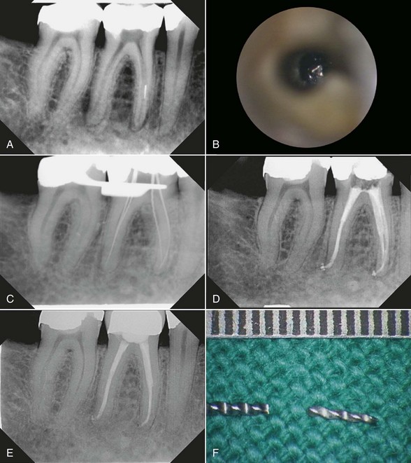
FIG. 9-39 Removal of a separated NiTi instrument from a mesiolingual canal of a mandibular molar. A, Fragment located in the middle third of the root. B, Clinical aspect of the fragment after enlargement of the coronal third of the root canal with modified Gates-Glidden drills, visualized with an operating microscope (×25). C, Radiograph taken after removal of the fragment; four hand files have been inserted into the canals. D, Final radiograph shows slight widening of the coronal third of the mesiolingual canal and fully sealed canal systems. A full crown was placed immediately after obturation. E, Recall radiograph 5 years after obturation shows sound periradicular tissues. F, Removed fragment and separated file (gradation of ruler is 0.5 mm).
Disinfectants, Dentin Surface Modifiers, and Lubricants
Studies have demonstrated conclusively that mechanical instrumentation cannot sufficiently disinfect root canals, regardless of whether stainless steel80 or NiTi112 instruments are used (Fig. 9-40). Irrigation solutions are required to eradicate microbiota, and over time, a variety of chemicals have been promoted for this purpose. The ideal irrigant or combination of irrigants kills bacteria, dissolves necrotic tissue, lubricates the canal, removes the smear layer, and does not irritate healthy tissues.153,191 Some formaldehyde-containing materials are no longer recommended for clinical use, but many irrigating solutions and varying concentrations of commonly used materials are described in the literature. Some solutions used in the past were sterile saline, alcohol, hydrogen peroxide, NaOCl, and detergents (e.g., quaternary ammonium compounds, chlorhexidine, citric acids, and EDTA).399 The following section describes current irrigation solutions and gives some recommendations for their clinical use.
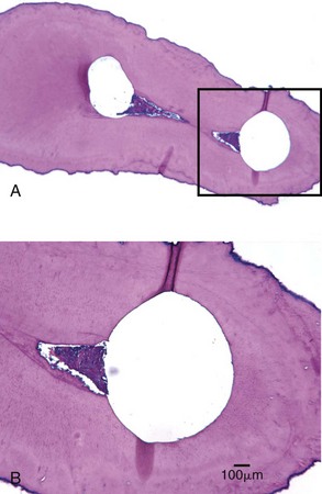
FIG. 9-40 Remaining potentially infected tissue in fins and isthmus configuration after preparation with rotary instruments. A, Cross section through a mesial root of a mandibular molar, middle to coronal third of the root. Both canals have been shaped; the left one is transported mesially (×10). B, Magnified view of rectangle in A. Note the presence of soft tissue in the isthmus area (×63).
(Courtesy Professor H. Messer.)
Sodium Hypochlorite
NaOCl encompasses many desirable properties of a main root canal irrigant and has therefore been described as the most ideal of all available rinsing agents.268,481 NaOCl has been in use for almost a century.111,446 A 0.5% solution of NaOCl was used effectively during World War I to clean contaminated wounds.111 In the endodontic field, NaOCl possesses a broad-spectrum antimicrobial activity against endodontic microorganisms and biofilms (Table 9-1), including microbiota difficult to eradicate from root canals, such as Enterococcus, Actinomyces, and Candida organisms.175,320,338,481
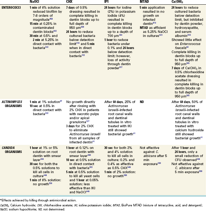
NaOCl dissolves organic material such as pulp tissue and collagen. If the organic portion of a smear layer is dissolved in NaOCl, and bacteria inside the main root canal, lateral canals, and dentinal tubules—if in direct contact with the irrigant—are destroyed, then to a minor degree, endotoxins may be eliminated.256,444
During endodontic therapy, NaOCl solutions are used at concentrations ranging from 0.5% to 6%. In infected dentin blocks, a 0.25% solution of NaOCl was sufficient to kill Enterococcus faecalis in 15 minutes; a concentration of 1% NaOCl required 1 hour to kill Candida albicans.368 In infected extracted teeth, Ruff et al.338 found that a 1-minute application of 6% NaOCl and 2% chlorhexidine were equally effective in eliminating microorganisms and statistically significantly superior to MTAD and 17% EDTA in eliminating Candida albicans infections.
Lower concentrations (e.g., 0.5% or 1%) dissolve mainly necrotic tissue.482 Higher concentrations allow better tissue dissolution but dissolve both necrotic and vital tissue, which is not always a desirable effect. In some cases, full-strength NaOCl (6%) may be indicated, but although higher concentrations may increase antibacterial effects in vitro,477 enhanced clinical effectiveness has not been demonstrated conclusively for concentrations stronger than 1%.399
Commercially available household bleach (Clorox, The Clorox Company, Oakland, CA) contains 6.15% NaOCl, has an alkaline pH of 11.4, and is hypertonic.399,482 Some authors recommend dilution of commercially available NaOCl with 1% bicarbonate instead of water to adjust the pH to a lower level.111,399 Others do not see any reduction of the aggressiveness on fresh tissue by buffering NaOCl and recommend diluting solutions of NaOCl with water to obtain less concentrated irrigation solutions.383,482
NaOCl only minimally removes dentin debris or smear layers (Fig. 9-41). Therefore, some authors recommend concurrent use of demineralizing agents to rid the root canal surface of a postinstrumentation smear layer and thus enhance cleaning of difficult-to-reach areas, such as dentinal tubules and lateral canals.81,283 When using NaOCl over extended periods of time during treatment, it should be mentioned that NaOCl seems to have an undesired side effect on the flexural strength of dentin. One study252 investigated the influence of irrigants on flexural strength of dentin bars and concluded that a 24-minute exposure time to a 2.5% hypochlorite solution caused a significant drop in flexural strength, while the modulus of elasticity was not altered during this time. Other authors discovered a lowering of both flexural and elastic strength after 2-hour submersion of dentin bars in NaOCl.11,164 The loss of calcium ions appears to be both dependent on NaOCl concentration (5% showing the greatest amount of decalcification) and time of exposure.351
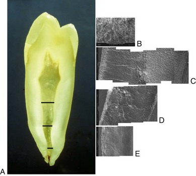
FIG. 9-41 Surface textures of an unprepared root canal at various levels. A, Ground section of a mandibular premolar. Areas viewed by scanning electron microscopy (SEM) are indicated by black lines. B, Canal surface at middle section, showing open dentinal tubules and typical calcospherites (×500). C-E, Coronal, middle, and apical areas as compound scanning electron micrographs. Note the numerous open tubules in C-D, whereas fewer tubules are visible in E (×200).
Chlorhexidine
Chlorhexidine (CHX) is a broad-spectrum antimicrobial agent effective against gram-negative and gram-positive bacteria (see Table 9-1). It has a cationic molecular component that attaches to negatively charged cell membrane areas, causing cell lysis.26,156 CHX as a mouth rinse and periodontal irrigant has been used in periodontal therapy, implantology, and cariology for many years to control dental plaque.130,232 Its use as an endodontic irrigant40,96,131,181,454 is based on its substantivity and long-lasting antimicrobial effect, which arises from binding to hydroxyapatite. However, it has not been shown to have more superior clinical properties than NaOCl. In fact, an in situ disinfection study suggests no additive effect on typical endodontic flora.259
When compared to CHX as an irrigant, it was found that hypochlorite significantly more often achieved negative cultures than CHX.333 When used as combination, NaOCl and CHX did not improve the antimicrobial activity of CHX against tested microorganisms.443
Some researchers found that CHX had significantly better antibacterial effects than Ca(OH)2 when tested on cultures.230 Combinations of CHX and Ca(OH)2 are available and show antimicrobial activity against obligate anaerobes, the combination in some studies augmenting the antibacterial effect of either medicament on certain species.315,385 However, 2% CHX gel alone was more effective than its combination with Ca(OH)2 against several tested microorganisms in other investigations.155,248 Medicaments containing 2% CHX have the ability to diffuse through dentin and display antimicrobial action on the outer root surface. The addition of CHX or iodine potassium iodide to an intracanal dressing of Ca(OH)2 in vitro did not affect the alkalinity (and hence the efficacy) of the Ca(OH)2 suspensions.385 Chlorhexidine (2%) has been advocated as a final rinse irrigant owing to its substantivity, which allows binding to dentin and sustained antimicrobial activity, especially in endodontic retreatment.480
Iodine Potassium Iodide
Iodine potassium iodide (IKI) is a traditional root canal disinfectant and is used in concentrations ranging from 2% to 5%. IKI kills a wide spectrum of microorganisms found in root canals (see Table 9-1) but shows relatively low toxicity in experiments using tissue cultures.398 Iodine acts as an oxidizing agent by reacting with free sulfhydryl groups of bacterial enzymes, cleaving disulfide bonds. E. faecalis often is associated with therapy-resistant periapical infections (see Chapter 15), and combinations of IKI and CHX may be able to kill Ca(OH)2-resistant bacteria more efficiently. One study385 evaluated the antibacterial activity of a combination of Ca(OH)2 with IKI or CHX in infected bovine dentin blocks. Although Ca(OH)2 alone was unable to destroy E. faecalis inside dentinal tubules, Ca(OH)2 mixed with either IKI or CHX effectively disinfected dentin. Others31 demonstrated that IKI was able to eliminate E. faecalis from bovine root dentin when used with a 15-minute contact time. An obvious disadvantage of iodine is a possible allergic reaction in some patients.
MTAD
BioPure (DENTSPLY Tulsa Dental), also known as MTAD (mixture of tetracycline, acid, and detergent), is an irrigation solution that contains doxycycline, citric acid, and a surface-active detergent (Tween 80).423 Chemicals and their combinations as root canal irrigants are developed constantly, including solutions based on antibiotics. However, doxycycline and other locally applied antibiotics have been unable to destroy microbiota organized in biofilms. One research group282 investigated the effect of five antibiotics on a mature biofilm after 8 days of growth on dentin; in their experiment, none of the topically applied substances could eradicate the biofilm. Use of these irrigants is also controversial because of the emergence of increasingly resistant strains of bacteria (e.g., therapy-resistant enterococci), which may be due to overprescription of antibiotics in general. The increased risk of host sensitization by local antibiotics can be circumvented to some degree by using the antibiotic as a dressing. Because exposure to vital tissues is limited, higher microbicidal concentrations may be used.269 A number of antibiotics, including erythromycin, chloramphenicol, tetracycline, and vancomycin, have been tested successfully against enterococci. In one study, investigators evaluated microbial susceptibility to different antibiotics in vitro and found that enterococcal isolates were resistant to benzylpenicillin, ampicillin, clindamycin, metronidazole, and tetracycline but sensitive to erythromycin and vancomycin.110 Another investigation202 used extracted teeth infected with E. faecalis and compared the efficacy of NaOCl and EDTA versus NaOCl and MTAD. They concluded that although the NaOCl/EDTA combination consistently disinfected the test specimens, almost half of the teeth rinsed with NaOCl/BioPure MTAD remained contaminated.202 In a recent study,371 doxycycline was replaced with CHX in one of the test groups of E. faecalis–infected teeth. Whereas no specimens that were cleaned with MTAD or MTAD + CHX showed the presence of residual bacteria, 70% of the samples rinsed with CHX as a substitute for doxycycline demonstrated growth of E. faecalis.
The citric acid component in MTAD effectively removed a smear layer.44,372,421 Under these conditions, BioPure MTAD was more aggressive in eroding dentin than EDTA. In another investigation,410 however, the addition of NaOCl was necessary to achieve dissolution of organic matter.
Ethylenediamine Tetra-Acetic Acid
EDTA came into use in endodontics in 1957283; chelators such as EDTA create a stable calcium complex with dentin mud, smear layers, or calcific deposits along the canal walls. This may help prevent apical blockage (Fig. 9-42) and aid disinfection by improving access of solutions through removal of the smear layer.
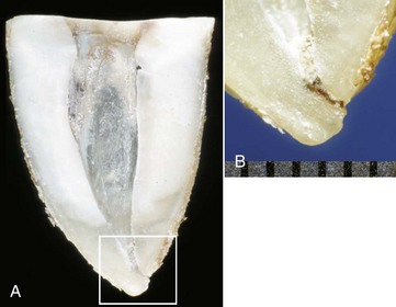
FIG. 9-42 Presence of dentin dust as a possible source of microbial irritation. Tooth #18 underwent root canal therapy. The clinician noted an apical blockage but was unable to bypass it. Unfortunately, intense pain persisted and at the patient’s request, the tooth was extracted a week later. A, Mesial root of tooth #18; mesial dentin has been removed. B, Magnified view (×125) of rectangle in A shows an apical block (gradation of ruler is 0.5 mm).
Neutral EDTA (17% concentration) showed a higher degree of decalcification of dentin surfaces than RC-Prep (a gel-type preparation of EDTA), although its effect was reduced in apical regions.441 Similar to MTAD, RC-Prep did not erode the surface dentin layer.421
The effect of chelators in negotiating narrow, tortuous, calcified canals to establish patency depends on both canal width and the amount of active substance available, since the demineralization process continues until all chelators have formed complexes with calcium.191,485 Calcium binding results in the release of protons, and EDTA loses its efficiency in an acidic environment. Thus the action of EDTA is thought to be self-limiting.367 In one study, demineralization up to a depth of 50 µm into dentin was demonstrated for EDTA solutions191; however, other reports demonstrated significant erosion after irrigation with EDTA.421
A comparison of bacterial growth inhibition showed that the antibacterial effects of EDTA were stronger than citric acid and 0.5% NaOCl but weaker than 2.5% NaOCl and 0.2% CHX.379 EDTA had a significantly better antimicrobial effect than saline solution. It exerts it strongest effect when used synergistically with NaOCl, although no disinfecting effect on colonized dentin could be demonstrated.181
Recent reports have indicated that several disinfecting agents such as Ca(OH)2, IKI, and CHX are inhibited in the presence of dentin.169,317,318 Moreover, chemical analyses indicated that chlorine, the active agent in NaOCl, is inactivated by EDTA.161,483 In light of these facts, in addition to the unproven effect of lubricants containing EDTA on rotary-instrument torque, use of these solutions probably should be limited to hand instrumentation early in a procedure. Moreover, an EDTA solution preferably is used at the end of a procedure to remove the smear layer but does not prevent future bacterial penetration between root canal fillings and canal walls.343,470,483 Clean, smear layer–free canal walls, tubulus openings, and entrances into lateral canals and isthmus areas, taken together with sufficient volume of NaOCl, ensures high disinfecting efficacy by enabling NaOCl to penetrate even into deeper dentin layers (Fig. 9-43).
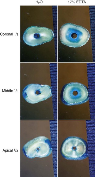
FIG. 9-43 Penetration of irrigants into dentinal tubules after root canal preparation with different dentin pretreatments. Left column, Irrigation with tap water and then with blue dye. Right column, Smear layer is removed with 17% EDTA, applied in high volume and with a 30-gauge needle, followed by irrigation with blue dye. Note the comparable diffusion of dye in the apical sections, whereas dye penetrated deeper into the dentin in the two coronal sections.
Calcium Hydroxide
Ca(OH)2 via its alkaline pH is generally very effective at eradicating intraradicular bacteria, with the exception of E. faecalis.133 Increased effectiveness was observed when Ca(OH)2 was mixed with some common irrigating solutions. Although additive effects could not be confirmed, and a reduction in the antimicrobial action of CHX was detected,176 it appears that Ca(OH)2 mixed with IKI or CHX may be able to kill Ca(OH)2-resistant bacteria385 (Box 9-4).
Unfortunately, it is not as effective when used short term and is not recommended as an irrigant but rather as an interappointment dressing.388 To achieve optimal antimicrobial activity, therefore, it requires prolonged exposure36 or higher temperatures for use as an endodontic irrigant.131
Other Irrigants
Electrochemically activated water (also known as oxidative potential water) recently was tested as a potential irrigant.166,250,391 Although this solution is active against bacteria166 and removes the smear layer,249 no assessment of its clinical potential is available, and in vitro research indicates that NaOCl is a superior disinfectant.166
Hydrogen peroxide traditionally has been used as an irrigant in conjunction with NaOCl; however, no additional benefit beyond NaOCl was registered.181
Some authors have advocated the use of 0.2% or 0.5% CHX in addition to NaOCl,169,181 either as an irrigant or mixed with Ca(OH)2 as an interappointment medicament. These combinations can overcome the inhibiting effect of dentin dust on conventional medicaments169,318 and can optimize their antimicrobial properties against certain resistant bacteria and yeasts.449,451
Recently, one group233 compared NaOCl with a final 17% EDTA rinse with an equal mixture of 2% NaOCl and 18% etidronic acid during and after instrumentation and a protocol involving 1% NaOCl during preparation and 2.25% peracetic acid after instrumentation. The results indicated that both acids had a similar effect on a smear layer as EDTA but with less demineralization of intratubular dentin. Strong demineralization has been shown to have a negative influence on canal sealability.115
Lubricants
In root canal treatment, lubricants are mostly used to emulsify and keep in suspension debris produced by mechanical instrumentation. Although irrigation solutions serve as lubricants, special gel-type substances are also marketed. Two of these are wax-based RC-Prep, which contains EDTA and urea peroxide, and glycol-based Glyde. Another purported function of lubricants is to facilitate the mechanical action of endodontic hand or rotary files. A study evaluating the effects of lubrication on cutting efficiency found that tap water and 2.5% NaOCl solutions increased cutting efficiency compared with dry conditions.478 The authors of this study cited the ability of a lubricant to remove debris as the factor for the increased efficiency. Similarly, a reduction of torque scores was found when canals in normed dentin disks were prepared with ProFile and ProTaper instruments under irrigation, but the use of a gel-type lubricant resulted in similar torques as in dry, nonlubricated canals.60,304
In summary, irrigation is an indispensable step in root canal treatment to ensure disinfection. The tissue-dissolving and disinfecting properties of NaOCl currently make it the irrigant of choice. EDTA should be used at the end of a procedure to remove the smear layer, followed by another flush with NaOCl for maximum cleaning efficiency. This strategy also minimizes inactivation of NaOCl by chemical interactions.161,481
Cleaning and Shaping: Clinical Issues
Endodontists widely agree that a major biologic aim of endodontic therapy is to eliminate apical periodontitis by disinfection and sealing of root canal systems. However, considerable disagreement exists over the way this goal should be achieved (see Fig. 9-9). Although “cleaning and shaping” accurately describes the mechanical procedures,337 it should be emphasized that “shaping and cleaning” more correctly reflects the fact that enlarged canals direct and facilitate the cleaning action of irrigants and the removal of infected dentin.
Microorganisms in the pulp cavity and coronal root canal may be readily killed by irrigants early in a procedure, but bacteria in less accessible canal areas still can elicit apical periodontitis. These bacteria can be eradicated only after root canal preparation.
Biologic Objectives
Some have suggested that canals should be prepared to a uniform and continuous taper361; however, this mechanical objective likely addresses obturation rather than antimicrobial efficacy. The preparation shape and antimicrobial efficacy are intimately related through the removal of infected dentin and the delivery of irrigants.185
Traditionally, fluids have been delivered to root canals passively by syringe and needle (Fig. 9-44). Active systems such as the NIT are still in an experimental phase.245 When delivered passively, irrigants have been shown to progress only 1 mm farther than the tip of the needle.323 Enlarged apical canals are likely to allow increasingly deeper needle placement (see Fig. 9-44), and this improves débridement and disinfection of canals.7,17,135,434 Nevertheless, thorough cleaning of the most apical part of any preparation remains difficult,466 especially in narrow and curved canals.180,295,329
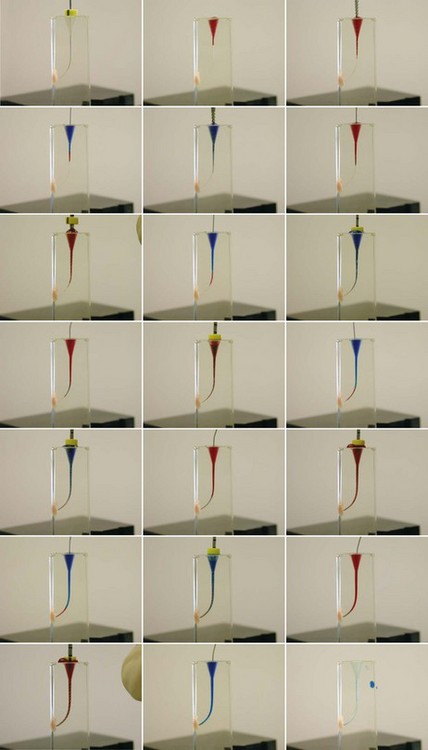
FIG. 9-44 Irrigation and movement of irrigants depends on canal shape. Sequential enlargement of a canal in clear plastic block was performed with a sequence of ProFile instruments in accordance with the manufacturer’s recommendations. Alternating irrigation with blue and red fluid was done after each preparation step. Note the apical presence of irrigant after sufficient shape has been provided. Note the distribution of fluid immediately after irrigation with a 30-gauge needle.
Mechanical Objectives
An important mechanical objective of root canal instrumentation is full incorporation of the original canals into the prepared shape, meaning that all root canal surfaces are mechanically prepared (green areas in Fig. 9-45, A and B); however, this goal is unlikely to be met with current techniques.291,310
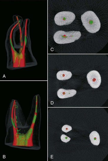
FIG. 9-45 Example of a desired shape, with the original root canal fully incorporated into the prepared outline. A-B, Micro–computed tomography reconstructions in clinical and mesiodistal views of a maxillary molar prepared with a NiTi rotary system. The green area indicates the pretreatment shape, and the red area indicates the posttreatment shape. Areas of mixed red and green indicate no change (i.e., no removal of radicular dentin). C-E, Cross sections of the coronal, middle, and apical thirds; the pretreatment cross sections (green) are encircled by the posttreatment outlines (red) in most areas.
(A-B from Hübscher W, Barbakow F, Peters OA: Root-canal preparation with FlexMaster: canal shapes analysed by micro-computed tomography. Int Endod J 36:740–747, 2003.)
Preparation errors such as zips and perforations should be absent. Although these and other procedural problems (Fig. 9-46) per se may not affect the probability of a favorable outcome,229 they may leave parts of the root canal system inaccessible for disinfection.

FIG. 9-46 Schematic diagrams showing the most common preparation errors. A, Apical zip. B, Ledge. C, Apical zip with perforation. D, Ledge with perforation.
Another important mechanical objective is to leave as much radicular dentin as possible so as not to weaken the root structure, thereby preventing vertical fractures. Although no definitive minimal radicular thickness has been established, 0.3 mm is considered critical.228 Even pretreatment, wall thickness of 1 mm and below has been demonstrated.147 Straightening of canal paths can lead to minimal remaining wall thicknesses (Fig. 9-47); this underlines the need for adequate access cavity preparation and optimal enlargement of the coronal third of the root canal.
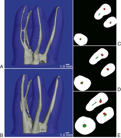
FIG. 9-47 Example of excessive thinning of dental structure during root canal treatment. A-B, Micro–computed tomography reconstructions show pretreatment and posttreatment root canal geometry of a maxillary molar. C-E, Cross sections of the coronal, middle, and apical thirds with pretreatment canal cross sections. Note the transportation and thinning, in particular, in the main mesiobuccal canal.
Two primary mechanical elements are the apical width and the endpoint of the prepared shape in relation to the apical anatomy. Traditional treatment has held that canal preparation and subsequent obturation should terminate at the apical constriction, the narrowest diameter of the canal. This point is believed to coincide with the cementodentinal junction (CDJ) (see Chapter 7). This definition of working length is based on histologic sections and ground specimens. However, the position and anatomy of the CDJ varies considerably from tooth to tooth, from root to root, and from wall to wall in each canal. Moreover, the CDJ cannot be located precisely on radiographs. For this reason, some have advocated terminating the preparation 0.5 to 1 mm short of the radiographic apex in necrotic cases and 1 to 2 mm short177,332,468 in cases involving irreversible pulpitis. In this way, preparation would take place inside the root canal. Although there is no definitive validation for this strategy at present,352 well-controlled follow-up studies seem to support it.387,389
However, working to shorter lengths could lead to the accumulation and retention of debris, which may result in apical blockage (see Fig. 9-42). Such blockage (which consists of collagen fibers, dentin mud, and most importantly, residual bacteria) inside apical canal areas is a major cause of persistent or recurrent apical periodontitis,172,276,378 currently termed posttreatment disease138,462 (also see Chapter 24). Additionally, because of the creation of apical blockage, working to short lengths may contribute to procedural errors such as apical perforations and fractured instruments.
The electronic apex locator has helped clinicians identify the position of apical foramina more accurately; the development of this instrument made it possible to work more precisely and routinely as close as 0.5 mm to the canal terminus (see Chapter 8).
Concepts and Strategies
Two factors are closely related to the preparation length: use of a patency file and the apical width. A patency file is a small K-file (usually a size #10 or #15) that is passively extended just through the apical foramen.
Use of a patency file has been suggested for most rotary techniques. This step is believed to remove accumulated debris and help maintain working length. However, the issue is controversial, and many U.S. dental schools did not teach this concept, at least not until recently.82 Moreover, investigators152 demonstrated that the use of patency files of varying sizes did not prevent preparation errors.
One concern with the patency file was that instead of having a cleaning effect, the file would push contaminated debris through the foramen. However, an in vitro study suggested that the risk of inoculation was minimal when canals were filled with NaOCl.198 Maintaining patency throughout an endodontic procedure does not lead to an increase in posttreatment symptoms.25 No definitive evidence exists either favoring or disproving the use of a patency file, but clinical experience suggests that this technique involves relatively little risk and provides some benefit as long as small files are used carefully.
Like the position of the apical constriction, apical diameters are difficult to assess clinically.220 Some have recommended gauging canal diameters by passing a series of fine files apically until one fits snugly. However, such an approach is likely to result in underestimation of the diameter.458 This is a crucial point because the initial canal size is a major determinant for the desired final apical diameter.
An ongoing debate exists between those who prefer smaller apical preparations combined with tapered shapes and those who favor larger apical preparations for better removal of infected dentin and to allow irrigation fluids access to the apical areas. Both sides stress the importance of maintaining the original path of the canal during preparation; otherwise, bacteria infecting the apical third of the root canal may not be reached by a sufficient bactericidal concentration of an antimicrobial agent.271 Investigators obtained a higher percentage of bacterial elimination in single-root canal systems by using a combination of significant enlargement of the apical third and NaOCl irrigation.89 Preparation errors (e.g., zips, canal transportation) can occur with wide preparations when either stainless steel or NiTi instruments are used (see Fig. 9-46).
Thorough disinfection of the apical part of a root canal is essential, because this area is likely to contain intraradicular bacteria.277 Wider apical preparations remove potentially infected dentin, allowing the delivering needle and subsequently the antimicrobial irrigant to penetrate the root canal more deeply.97,135
A study investigating rotary NiTi files of three tapers (#.06, #.08, and #.10) with file tips in sizes #20, #30, and #40 showed that size #20 instruments left significantly more debris in the apical third compared with size #40 instruments.434 On the other hand, a study in which half the samples were prepared to a size #25 file and the other half to a size #40 file found no statistically significant difference in bacterial growth after instrumentation, with no growth observed after 1 week of treatment with a Ca(OH)2 dressing.473 Another study compared step-down sequences with additional apical enlargement to ISO size #35 or a serial step-back technique with no apical enlargement. NaOCl and EDTA were used as irrigants. In that study, no significant difference was detected in colony-forming units with or without apical enlargement.102 These researchers concluded that dentin removal in the apical third might be unnecessary if a suitable coronal taper is achieved.
Despite the disagreement over the appropriate width of a preparation (Table 9-2), the distillation of all these studies suggest that root canal preparations should be confined to the canal space, should be sufficiently wide, and should incorporate the original root canal cross sections (see Fig. 9-45). This way, routine root canal treatment results in favorable outcomes at various levels of clinicians’ expertise (Fig. 9-48).
TABLE 9-2 Characteristics of Wide and Narrow Apical Preparations
| Root Canal Preparation | Benefits | Drawbacks |
|---|---|---|
| Narrow Apex | ||
| Wide Apex |
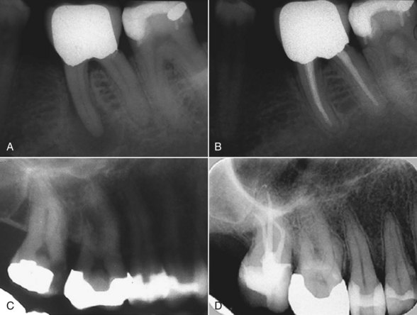
FIG. 9-48 Routine cases treated according to the principles discussed in this chapter. Biologic and mechanical aims were maintained at varying levels of expertise. A, Asymptomatic tooth #18 with periradicular lesion; endodontic treatment was indicated. B, Recall radiograph after 18 months (treatment was performed by fourth-year student at Zurich Dental School). C, Pretreatment radiograph of tooth #2, which was diagnosed with irreversible pulpitis. D, Recall radiograph 2 years later shows sound periradicular tissue; the tooth is clinically symptom free (treatment was performed by an endodontist).
Canal Preparation Techniques
The traditional cleaning and shaping strategy (the step-back technique) focused on the initial preparation of the apical third of the root canal system, followed by various flaring techniques to facilitate obturation.158,354,420 In an attempt to reach the canal terminus, the clinician first selected a small file, placed an appropriate curve on the instrument, and then tried to work the file to full length. If the terminus could not be reached, the file was removed and, after irrigation, either the same file or a smaller one was inserted. However, not infrequently full length may not be reached because of blockage or coronal binding.
Coronal binding is caused by overhangs at the orifice level and also occurs when the canal is less tapered than an instrument, thus binding somewhere coronally. Moreover, a straight root often has a curved canal; buccal and lingual curvatures that cannot be seen on radiographs also need to be detected.103,312 Passing a precurved negotiating file through a coronally tight canal will straighten the instrument.395 Nonflared canals do not allow efficient irrigation, which further predisposes to blockage.
Various instrumentation sequences have been developed for hand and rotary instruments; these are discussed later in the chapter. However, the shape of the access cavity is the prerequisite that must be optimized before any canal preparation can take place (see Chapter 7).
One approach to the preparation of an adequate access cavity (Fig. 9-49) involves the use of a cylindrical diamond or fissure bur, a safety-ended drill for additional enlargement, and round burs to remove overhangs on outward strokes. The access cavity shape must allow instruments unimpeded access to the middle third of the root canal system. Ultrasonically powered instruments used under an operating microscope greatly facilitate removal of mesial dentin shelves in mandibular molars (Fig. 9-50, A and B) and other teeth. Preexisting restorations allow for ideal access cavities that serve as reservoirs of irrigants (see Fig. 9-50, C).
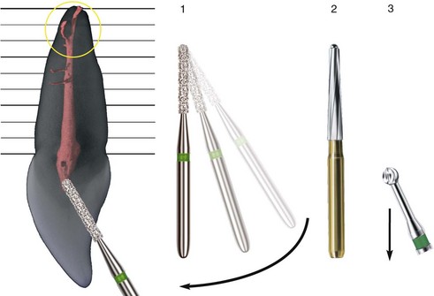
FIG. 9-49 Sequence of instruments used for optimal preparation of an access cavity (e.g., in an incisor). A parallel-sided diamond or steel bur is used to remove overlying enamel in a 90-degree angle toward the enamel surface (1). The bur is then tilted vertically to allow straight-line access to the root canal (arrow). A bur with a noncutting tip (e.g., Endo-Z bur or ball-tipped diamond bur) is then used to refine access (2). Overhangs or pulp horns filled with soft tissue are finally cleared with a round bur used in a brushing or pulling motion (3).

FIG. 9-50 Clinical views of an access cavity in a mandibular molar as seen through an operating microscope (×20). A, Modification with an ultrasonically activated tip. B, Access cavity after modification. C, Cavity is flooded with 1% sodium hypochlorite.
Basic cleaning and shaping strategies for root canal preparation can be categorized as crown-down, step-back, apical widening, and hybrid techniques. In a crown-down approach, the clinician passively inserts a large instrument into the canal up to a depth that allows easy progress. The next smaller instrument then is used to progress deeper into the canal; the third instrument follows, and this process continues until the terminus is reached. Both hand and rotary instruments may be used in a crown-down manner. However, instrument sets with various tip diameters and tapers allow the use of either decreasing tapers or decreasing diameters for apical progress. Debate continues as to which of those strategies is superior for avoiding taper lock; currently no compelling evidence favors either of them.
In the step-back approach, working lengths decrease in a stepwise manner with increasing instrument size. This prevents less flexible instruments from creating ledges in apical curves while producing a taper for ease of obturation.
As discussed previously, the aim of apical widening is to fully prepare apical canal areas for optimal irrigation efficacy and overall antimicrobial activity. Recently, apical enlargement has been broken down into three phases: preenlargement, apical enlargement, and apical finishing.448
Most rotary techniques require a crown-down approach to minimize torsional loads57 and reduce the risk of instrument fracture. Used sequentially, the crown-down technique can help to enlarge canals further. All basic techniques described so far may be combined into a hybrid technique to eliminate or reduce the shortcomings of individual instruments.
Root canal preparation can be broken down into a series of steps that parallel the insertion depths of individual instruments. Anatomic studies and clinical experience suggest that most teeth are 19 to 25 mm long. Most clinical crowns are approximately 10 mm long, and most roots range from 9 to 15 mm in length. Roots, therefore, can be divided into thirds that are 3 to 5 mm long.
Provided adequate tools are used and the access cavity design is appropriate, excessive thinning of radicular structures can be avoided (see Fig. 9-47). Vertical root fractures and perforations are possible outcomes of excessive removal of radicular dentin in zones that have been termed danger zones.20 Overenthusiastic filing, for example, may lead to more procedural errors (see Fig. 9-20). On the other hand, ideal preparation forms without any preparation errors and with circular incorporation of the original canal cross sections may be achieved with suitable techniques (see Fig. 9-45).
Preenlargement of the coronal half to two thirds to allow files unimpeded access gives the clinician better tactile control in directing small, adequately precurved negotiating files into the delicate apical third (Fig. 9-51). Gates-Glidden drills can be used sequentially to enlarge the coronal third of the canal in teeth with straight roots (Fig. 9-52). Both step-back and step-down sequences have been recommended.
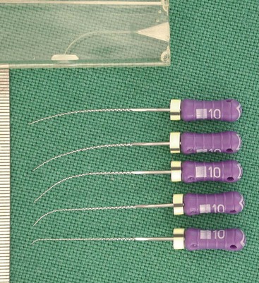
FIG. 9-51 Various precurved, stainless steel hand files for pathfinding and gauging. Compare the curves in the instruments to the ones in a plastic training block (gradation of ruler is 0.5 mm).
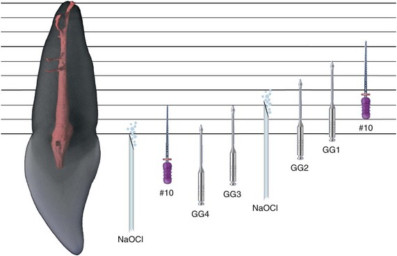
FIG. 9-52 Diagram of coronal enlargement in a maxillary anterior tooth. After preparation of the access cavity (see Figure 9-49) and copious irrigation, Gates-Glidden burs are used in a step-down manner to enlarge the orifice and provide straight-line access into the middle third of the canal. Precurved size #10 K-files are used to explore the canal path and dimension.
Besides GG burs, various instruments have been introduced or suggested for coronal preenlargement, such as the ProFile orifice shapers, GT accessory files, the ProTaper Sx, the FlexMaster Intro file, and the size #40, #.10 taper or size #35, #.08 taper RaCe files. These instruments are better suited to and safer for more difficult cases (Fig. 9-53).
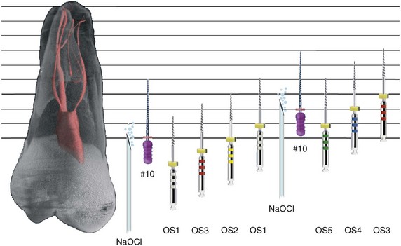
FIG. 9-53 Diagram of coronal enlargement in a more complicated maxillary posterior tooth. This maxillary molar presents several difficulties, including a narrow mesiobuccal canal that exits the pulp cavity at an angle. A possible approach in a case involving difficult entry into the root canal system is to use a small orifice shaper (OS1) after ensuring a coronal glide path with a K-file. Use of a sequence of orifice shapers (OS3 to OS1) then allows penetration into the middle third of the root canal. Wider canals can accept a second sequence of orifice shapers. Copious irrigation and securing a glide path with a size #10 K-file are prerequisites for use of NiTi rotary instruments.
Once the coronal portions of a canal have been enlarged, the apical canal areas can be more efficiently prepared. Better clinical results are obtained with optimized access, regardless of the preparation technique used (Fig. 9-54). Only after preenlargement can fine scouting files (also used before rotary files in the coronal areas) provide information about the root canal paths. Preenlarged canals may accommodate hand files, which can be used to gather specific information about the apical third’s cross-sectional diameter and anatomy.
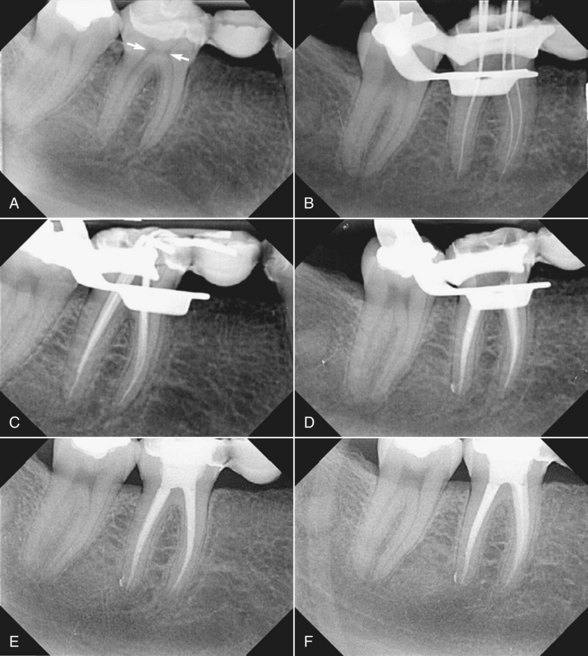
FIG. 9-54 Clinical example of the importance of straight-line access to the middle third of the root canal. A, Pretreatment radiograph of tooth #30, diagnosed with irreversible pulpitis. This tooth serves as a retainer for a metal-free, fixed partial denture. Note the prominent dentin shelves (arrows). B, Working length radiograph with hand instruments inserted into the mesial and distal canals. C, Cone-fit radiograph showing tapered preparations after removal of the dentin shelves. D, Posttreatment radiograph after thermoplastic compaction of gutta-percha. E-F, Follow-up radiographs at 2 and 4 years. The tooth is clinically symptom free, and the periodontal ligament appears to be within normal limits.
Hand Instrumentation
Standardized Technique
The standardized technique adopts the same working length definition for all instruments introduced into a root canal and therefore relies on the inherent shape of the instruments to impart the final shape to the canal. Negotiation of fine canals is initiated with lubricated fine files in a so-called watch-winding movement. These files are advanced to working length and worked either in the same hand movement or with “quarter-turn-and-pull” until a next larger instrument may be used. Conceptually, the final shape should be predicted by the last-used instrument. A single matching gutta-percha point may then be used for root canal filling. In reality, this concept is often violated: curved canals shaped with the standardized technique will be wider than the last used instrument,19 exacerbated by the pulling portion of the hand movement. Moreover, adequate compaction of gutta percha in such small a taper (~.02) is difficult or impossible18 (see Chapter 11).
Step-Back Technique
Realizing the importance of a shape larger than that produced with the standardized approach, one investigator457 suggested the step-back technique, incorporating a stepwise reduction of the working length for larger files, typically in 1-mm or 0.5-mm steps, resulting in flared shapes with 0.05 and 0.10 taper, respectively. Incrementally reducing the working length when using larger and stiffer instruments also reduced the incidence of preparation errors, in particular in curved canals. This concept appeared to be clinically very effective.273
Although the step-back technique was primarily designed to avoid preparation errors in curved canals, it applies to the preparation of apparently103,356 straight canals as well. Several modifications of the step-back technique have been described over the years. Another investigator420 advocated the insertion of progressively larger hand instruments as deep as they would passively go in order to explore and provide some enlargement prior to reaching the working length.
Step-Down Technique
Other investigators150 described a different approach. They advocated shaping the coronal aspect of a root canal first before apical instrumentation commenced. This technique is intended to minimize or eliminate the amount of necrotic debris that could be extruded through the apical foramen during instrumentation134; moreover, by first flaring the coronal two-thirds of the canal, apical instruments are unimpeded through most of their length. This in turn may facilitate greater control and less chance of zipping near the apical constriction.225
Crown-Down Technique
Numerous modifications of the original step-down technique have been introduced, including the description of the crown-down technique.136,253,348 The more typical step-down technique includes the use of a stainless steel K-file exploring the apical constriction and establishing working length. In contrast, a crown-down technique relies more on coronal flaring and then determination of the working length later in the procedure.
To ensure penetration during step-down, one may have to enlarge the coronal third of the canal with progressively smaller GG drills or with other rotary instruments. Irrigation should follow the use of each instrument and recapitulation after every other instrument. To properly enlarge the apical third and to round out ovoid shape and lateral canal orifices, a reverse order of instruments may be used starting with a size #20 (for example) and enlarging this region to a size #40 or #50 (for example). The tapered shape can be improved by stepping back up the canal with larger instruments, bearing in mind all the time the importance of irrigation and recapitulation.
The more typical crown-down, or double-flare technique136 consisted of an exploratory action with a small file, a crown-down portion with K-files of descending sizes, and an apical enlargement to size #40 or similar. The original technique included stepping back in 1-mm increments with ascending file sizes and frequent recapitulations with a small K-file and copious irrigation. It is further emphasized that significant wall contact should be avoided in the crown-down phase to reduce hydrostatic pressure and the possibility of blockage. Several studies347,348 demonstrated more centered preparations in teeth with curved root canals shaped with a modified double-flare technique and Flex-R files compared to shapes prepared with K-files and step-back technique. A double-flare technique was also suggested for ProFile rotary instruments.363
Balanced Force Technique
Regarding hand movements, a general agreement exists that the so-called balanced force technique creates the least canal aberrations with K-files. Researchers described this technique as a series of rotational movements for Flex-R files, but it can also be used for K-files and other hand instruments such as GT hand files. Many different explanations have been offered for the obvious and undisputed efficacy of the balanced force approach,91,221,336 but general agreement exists that it provides excellent canal-centering ability, superior to other techniques with hand instruments.29,69,226
The balanced force technique involves three or four steps.334 The first step (after passive insertion of an instrument into the canal) is a passive clockwise rotation of about 90 degrees to engage dentin (Fig. 9-55). In the second step, the instrument is held in the canal with adequate axial force and rotated counterclockwise to break loose the engaged dentin chips from the canal wall; this produces a characteristic clicking sound. Classically, in the third step, the file is removed with a clockwise rotation to be cleaned; however, because files used with the balanced force technique are not precurved, every linear outward stroke essentially is a filing stroke and may lead to some straightening of the canal path. Therefore, in many cases, the clinician may advance farther apically rather than withdrawing the file, depending on the grade of difficulty.